EP0503497A2 - Verschlussglied für ein Tintenbehälterteil und Aufzeichnungskopf damit versehen - Google Patents
Verschlussglied für ein Tintenbehälterteil und Aufzeichnungskopf damit versehen Download PDFInfo
- Publication number
- EP0503497A2 EP0503497A2 EP92103871A EP92103871A EP0503497A2 EP 0503497 A2 EP0503497 A2 EP 0503497A2 EP 92103871 A EP92103871 A EP 92103871A EP 92103871 A EP92103871 A EP 92103871A EP 0503497 A2 EP0503497 A2 EP 0503497A2
- Authority
- EP
- European Patent Office
- Prior art keywords
- ink
- sealing member
- recording head
- sealing
- pressure
- Prior art date
- Legal status (The legal status is an assumption and is not a legal conclusion. Google has not performed a legal analysis and makes no representation as to the accuracy of the status listed.)
- Granted
Links
Images






Classifications
-
- B—PERFORMING OPERATIONS; TRANSPORTING
- B41—PRINTING; LINING MACHINES; TYPEWRITERS; STAMPS
- B41J—TYPEWRITERS; SELECTIVE PRINTING MECHANISMS, i.e. MECHANISMS PRINTING OTHERWISE THAN FROM A FORME; CORRECTION OF TYPOGRAPHICAL ERRORS
- B41J2/00—Typewriters or selective printing mechanisms characterised by the printing or marking process for which they are designed
- B41J2/005—Typewriters or selective printing mechanisms characterised by the printing or marking process for which they are designed characterised by bringing liquid or particles selectively into contact with a printing material
- B41J2/01—Ink jet
- B41J2/17—Ink jet characterised by ink handling
- B41J2/175—Ink supply systems ; Circuit parts therefor
- B41J2/17503—Ink cartridges
- B41J2/17536—Protection of cartridges or parts thereof, e.g. tape
-
- B—PERFORMING OPERATIONS; TRANSPORTING
- B41—PRINTING; LINING MACHINES; TYPEWRITERS; STAMPS
- B41J—TYPEWRITERS; SELECTIVE PRINTING MECHANISMS, i.e. MECHANISMS PRINTING OTHERWISE THAN FROM A FORME; CORRECTION OF TYPOGRAPHICAL ERRORS
- B41J2/00—Typewriters or selective printing mechanisms characterised by the printing or marking process for which they are designed
- B41J2/005—Typewriters or selective printing mechanisms characterised by the printing or marking process for which they are designed characterised by bringing liquid or particles selectively into contact with a printing material
- B41J2/01—Ink jet
- B41J2/135—Nozzles
- B41J2/165—Prevention or detection of nozzle clogging, e.g. cleaning, capping or moistening for nozzles
- B41J2/16505—Caps, spittoons or covers for cleaning or preventing drying out
- B41J2/16508—Caps, spittoons or covers for cleaning or preventing drying out connected with the printer frame
-
- B—PERFORMING OPERATIONS; TRANSPORTING
- B41—PRINTING; LINING MACHINES; TYPEWRITERS; STAMPS
- B41J—TYPEWRITERS; SELECTIVE PRINTING MECHANISMS, i.e. MECHANISMS PRINTING OTHERWISE THAN FROM A FORME; CORRECTION OF TYPOGRAPHICAL ERRORS
- B41J2/00—Typewriters or selective printing mechanisms characterised by the printing or marking process for which they are designed
- B41J2/005—Typewriters or selective printing mechanisms characterised by the printing or marking process for which they are designed characterised by bringing liquid or particles selectively into contact with a printing material
- B41J2/01—Ink jet
- B41J2/17—Ink jet characterised by ink handling
- B41J2/175—Ink supply systems ; Circuit parts therefor
- B41J2/17503—Ink cartridges
- B41J2/1752—Mounting within the printer
-
- B—PERFORMING OPERATIONS; TRANSPORTING
- B41—PRINTING; LINING MACHINES; TYPEWRITERS; STAMPS
- B41J—TYPEWRITERS; SELECTIVE PRINTING MECHANISMS, i.e. MECHANISMS PRINTING OTHERWISE THAN FROM A FORME; CORRECTION OF TYPOGRAPHICAL ERRORS
- B41J2/00—Typewriters or selective printing mechanisms characterised by the printing or marking process for which they are designed
- B41J2/005—Typewriters or selective printing mechanisms characterised by the printing or marking process for which they are designed characterised by bringing liquid or particles selectively into contact with a printing material
- B41J2/01—Ink jet
- B41J2/17—Ink jet characterised by ink handling
- B41J2/175—Ink supply systems ; Circuit parts therefor
- B41J2/17503—Ink cartridges
- B41J2/17533—Storage or packaging of ink cartridges
Definitions
- the present invention relates to a thin film member useful for sealing an ink outlet (an ejection outlet or the like) or an air communication hole, or for fixing tentatively an article of an ink-recording head.
- the present invention also relates to a recording head employing the thin film member.
- the thin film of the present invention is suitably used as a sealing tape.
- Japanese Patent Application Laid-Open No. 60-204348 discloses a cap-shaped protecting member having an ink absorbent provided at the ejection outlet; and Japanese Patent Application Laid-Open No. 61-125851 discloses a sealing tape composed basically of a vinylidene chloride resin for protecting the ejection outlet.
- the conventional capping devices are liable to cause overflow of ink during transportation of an ink-jet recording apparatus owing to tossing in the transportation or other causes to soil the interior of the recording apparatus.
- the present invention is directed to exclude the use of a cap-shaped protecting member to fix the sealing member by giving it suitable conditions to seal an ink container portion.
- a conventional protecting sealing tape for example, which is constituted at least of a support and a pressure-sensitive adhesive layer laminated thereon is not satisfactory in sealing of an irregular face, resulting in gradual peeling during a long term of storing to cause leakage of ink.
- the sealing member is required to be capable of preventing ink leakage for a long term, even in the case where the sealed face has a stepped structure, an irregular surface structure, or a discontinuous structure.
- the present invention intends to provide a sealing member which is capable of preventing, by itself, ink leakage from an ink container during transportation, and which enables a long term of storage of an ink-jet recording head.
- the present invention also intends to provide a protective sealing tape for ink-jet recording head which allows immediate start of ink recording without adverse effect of an eluted matter from an adhering portion of the sealing member or a remaining adhesive matter after removal of the sealing member.
- the present invention provides a sealing member for sealing, with a pressure-sensitive adhesive portion thereof, a communicating hole or a joint portion between the interior and the exterior of a recording/container portion holding therein an ink, the sealing member exhibiting an yield point at a load of not more than 1 kgf/cm for a specimen of 10 mm wide at a stress rate of 200 mm/min ⁇ 10% according to JIS-K-7113.
- the present invention also provides a sealing member for sealing, with a pressure-sensitive adhesive portion thereof, a communicating hole or a joint portion between the interior and the exterior of a recording/container portion holding therein an ink, the sealing member exhibiting a folding load of not more than 0.10 g/cm for a specimen of 10 mm wide with a free length of 10 mm from the end of a specimen holder measured on the center of an electronic balance placed at a position 5 mm apart from the end of the specimen holder.
- the present invention further provides a recording head having an ink container, an energy-generating element for generating energy for ejecting an ink held in the ink container, an ink-ejecting portion corresponding to the energy-generating element, and a sealing member, the sealing member being as defined above.
- the sealing member is effective when it is applied onto a portion where an ink exists in proximity, the portion such as an ink ejecting portion corresponding to an energy-generating element of an ink-jet recording head.
- the pressure-sensitive adhesive comprises an acrylate ester copolymer crosslinked by an isocyanate, the acrylate ester copolymer being composed of at least 80 % by weight in total of an alkyl and/or alkoxyalkyl acrylate ester containing an hydroxy group, and an acrylate ester having a side chain of an alkyl or alkoxyalkyl group of 4 to 9 carbons.
- the aforementioned folding load of not more than 0.05 g/cm and not less than 0.01 g/cm of the sealing member enables effective sealing.
- the sealing member of the present invention is suitably used for ink-jet recording heads to protect the ejection portion thereof and to prevent ink leakage from the ejection outlet during a long term of storage.
- the sealing member of the present invention is readily peelable at the start of ink-jet recording even after a long term of storage of an ink-jet recording head, not causing soiling around the ink ejection outlet, thus enabling satisfactory ink-jet recording.
- the sealing member of the present invention can achieve by itself the above-mentioned objects without employing an additional structure, namely an additional protecting member (for example, a pressing member) to prevent the peeling.
- an additional protecting member for example, a pressing member
- Fig. 1A to Fig. 1C are rough perspective views of examples of the use of a seal tape of the present invention.
- Fig. 2 is a perspective view of an ink-jet cartridge of the present invention.
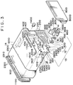
- Fig. 3 is an perspective exploded view of an ink cartridge of the present invention.
- Fig. 4 is a rough drawing illustrating a head portion of an ink cartridge of the present invention.
- Fig. 5 is a rough drawing of a lateral side of the head portion.
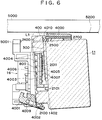
- Fig. 6 is a drawing for explaining the fitting up of a head to the main body of an ink-jet recording apparatus.
- Fig. 7 is a perspective view of a recording apparatus provided with a head of the present invention.
- Fig. 8A and Fig. 8B are rough drawings illustrating an example of a seal tape of the present invention, and a coating process.
- Fig. 9 illustrates an air communication hole of a head of the present invention.
- Fig. 10 illustrates a shape of the air communication hole.
- Fig. 11 illustrates a state of package of a cartridge of the present invention.
- Fig. 12A to Fig. 12C illustrates a constitution of an ink-feeding portion which connects an ink tank of a cartridge of the present invention with a recording head.
- Fig. 12A illustrates an ink-feeding portion.
- Fig. 12B illustrates a sealing ball.
- Fig. 12C illustrates an assemblage thereof.
- the sealing member of the present invention yields at a load of not more than 1 kgf/cm for a specimen of 10 mm wide at a stress rate of 200 mm/min ⁇ 10% according to JIS-K7113.
- No proper criterion has ever been given for evaluating a sealing properties for faces of such as an ejection outlet of an ink-jet recording head. Therefore, the investigation was began with study to provide a criterion for evaluation of the sealing properties on such a surface, in particular a surface for a joint portion including an inclined portion and a corner portion.
- the above-mentioned JIS-K-7113 itself is not a standard to be applied to a sealing member like the one of the present invention.
- the inventors of the present invention after comprehensive study, succeeded to evaluate the properties of a thin film having a pressure-sensitive adhesive as a sealing member by taking the load at yield point, as the evaluation criterion, for a specimen of 10 mm wide at stress rate of 200 mm/min ⁇ 10%.
- the load of 1 kgf/cm at the yield point is the critical criterion.
- the sealing member could not seal a jointed region stably for a long term.
- the measured load may be converted to the value for the width of 10 mm to denote the load at yield in terms of the kgf/cm unit as defined in the present invention.
- the evaluation criterion is that the sealing member has a folding load of not more than 0.10 g/cm, for a specimen of 10 mm wide with a free length of 10 mm from a supported end, at a position of 5 mm apart from the supported end and at the center of an electronic balance pan. This evaluation is found to be effective for specimens having a free length of at least 10 mm.
- the value of 0.10 g/cm is the critical criterion. At the folding load exceeding 0.07 g/cm, the peeling is remarkable, while at the folding load of not more than 0.10 g/cm, the sealing member achieves stable sealing effect for the ink container for a long term.
- the pressure-sensitive adhesive includes various known materials.
- acrylic materials particularly preferably acrylate ester copolymers crosslinked by an isocyanate, the acrylate ester copolymer being composed of at least 80 % by weight in total of a hydroxyalkyl acrylate and/or an alkoxyalkyl acrylate, and an acrylate ester having a side chain of an alkyl or alkoxyalkyl group of 4 to 9 carbons.
- the acrylic monomer for the pressure-sensitive acrylic material includes alkyl ester monomers such as methyl acrylate, ethyl acrylate, propyl acrylate, isopropyl acrylate, butyl acrylate, isobutyl acrylate, 2-methylbutyl acrylate, 2-ethylbutyl acrylate, 3-methylbutyl acrylate, 1,3-dimethylbutyl acrylate, pentyl acrylate, 3-pentyl acrylate, hexyl acrylate, 2-ethylhexyl acrylate, heptyl acrylate, 2-heptyl acrylate, octyl acrylate, 2-octyl acrylate, nonyl acrylate, and the like.
- alkyl ester monomers such as methyl acrylate, ethyl acrylate, propyl acrylate, isopropyl acrylate, butyl acrylate, isobutyl
- alkoxyalkyl ester monomers can also be used. Such a monomer is used in combination with the hydroxy-group-containing monomer in a total amount ranging from 50 to 100 % by weight, preferably from 50 to 80 % by weight.
- the polyvalent isocyanate compound includes tolylene diisocyanate, hexamethylene diisocyanate, diphenylmethane diisocyanate, isophorone diisocyanate, xylylene diisocyanate, bis(isocyanatomethyl)cyclohexane, dicyclohexylmethane diisocyanate, lysine diisocyanate, trimethylhexamethylene diisocyanate, adducts of tolylene diisocyanate and hexamethylene diisocyanate, urethane-modified compounds, allophanate-modified compounds, biuret-modified compounds, isocyanurate-modified compounds, urethane prepolymers (oligomeric compounds having an isocyanate group at each end), and the like.
- the cohesion property of the pressure-sensitive adhesives can be adjusted by various methods.
- a first method of adjusting the cohesion property of the pressure-sensitive adhesive is copolymerization with a hydroxy-group-containing monomer and crosslinking by use of a polyvalent isocyanate compound.
- the hydroxy-group-containing monomer includes 2-hydroxyethyl acrylate, 2-hydroxypropyl acrylate, hydroxybutyl acrylate, 2-hydroxyethyl methacrylate, 2-hydroxypropyl methacrylate, hydroxybutyl methacrylate, acrylate esters of polyhydric alcohol, methacrylate ester of polyhydric alcohol, an acrylate ester of ethylcarbitol, an acrylylate ester of methyltriglycol, 2-hydroxyethyl acryloylphosphate, propoxyethyl acrylate, and so forth.
- the hydroxy-group-containing monomer is used preferably in an amount ranging from 5 to 25 % by weight, and a part or the whole thereof is crosslinked by polyvalent isocyanate.
- a second method of adjusting the cohesion property of the pressure-sensitive adhesive is appropriate use of copolymerization component such as a methacrylate monomer, vinyl acetate, styrene, acrylonitrile, acrylamide, and methacrylamide.
- a component is preferably used in an amount ranging from 5 to 15 % by weight. From among the components, acrylonitrile, acrylamide, and methacrylamide are particularly suitable for the ink-jet recording head of the present invention.
- a third method of adjusting the cohesion property of the pressure-sensitive adhesive is crosslinking with a crosslinking monomer such as N-methylolacrylamide, N-methylolmethacrylamide, diacetonacrylamide, and butoxymethylacrylamide.
- the crosslinking monomer is preferably used in an amount ranging from 5 to 15 % by weight.
- the first method of the adjustment is preferably combined with the second or the third method.
- the pressure-sensitive adhesive employed in the present invention has higher chemical resistance against an ink-jet ink, giving less elution of organic compounds, containing less amount of polyvalent metal, and having excellent properties for protecting the nozzle surface of the ink-jet recording head.
- the pressure-sensitive adhesive may be produced by polymerizing the aforementioned materials by a known polymerization process into a high polymer having a weight-average molecular weight of from 250,000 to 1,000,000.
- the content of low polymers and remaining monomers are required to be as low as possible.
- the low polymer and the remaining monomer is removed preferably by reprecipitation.
- the polymer thus prepared is dissolved in a good solvent, and a diisocyanate is added thereto to provide a paint.
- the paint is applied onto a supporting film to form a pressure-sensitive adhesive layer of a dry thickness in the range of from 5 ⁇ m to 100 ⁇ m by a known coating method such as blade coating, air-knife coating, roll coating, brush coating, curtain coating, Chamblex coating, bar coating, gravure coating, and the like method, and the applied paint is dried in a conventional manner.
- the film may be subjected to an aging treatment at an appropriate temperature, if desired, for the purpose of stabilizing the properties of the pressure-sensitive adhesive.
- the support for the pressure-sensitive adhesive of the present invention may be of any material such as paper and plastic films, provided that the seal tape formed by combination of the support and the pressure-sensitive adhesive satisfies the aforementioned criterion of the present invention. Synthetic papers and films made from a plastic is suitable in view of the durability and the weatherability.
- the film material includes polyethylene terephthalate, polyethylene, polypropylene, polyvinyl chloride, polyvinylidene chloride, vinylidene chloride-vinyl chloride copolymers, polyvinyl fluoride, polyvinylidene fluoride, tetrafluoroethylene-ethylene copolymers, tetrafluoroethylene-hexafluoropropylene-perfluoroalkyl vinyl ether copolymers, and the like.
- polyethylene terephthalate, polyethylene, and polypropylene are preferred which generate no noxious gas on burning.
- the thickness of the support is preferably in the range of from 5 ⁇ m to 100 ⁇ m, more preferably from 10 ⁇ to 50 ⁇ m for use for a protecting seal tape, but is not limited thereto.
- the support may be colored by printing or immersion.
- the support is preferably pretreated physically by employing a high-frequency alternate electric field, ion radiation, electron radiation, corona discharge, and the like, or pretreated chemically by applying a coupling agent, or the like before application of the pressure-sensitive adhesive.
- the seal tape of the present invention may be laminated at the adhesive side onto a releasable base material, although it does not relates directly to the present invention.
- the protecting seal tape of the present invention is applicable onto an ink-repelling surface of the ejection outlet of an ink-jet recording head, giving satisfactory sealing properties without deterioration of the tape and the ejection outlet surface.
- the aforementioned ink-repelling surface means a surface having been treated with a treating agent such as a silicone oil, a fluorine-containing low molecular or high molecular compound, specifically including KP-801 (trade name, made by Shin-Etsu Silicone K.K.), Defenser (trade name, made by Dainippon Ink and Chemicals, Inc.), CTX-105 and -805 (trade name, made by Asahi Glass Co., Ltd.), Teflon AF (trade name, made by DuPont Co.), and so forth.
- a treating agent such as a silicone oil, a fluorine-containing low molecular or high molecular compound, specifically including KP-801 (trade name, made by Shin-Etsu Silicone K.K.), Defense
- the sealing member may be sticked in any method. However, the sealing member is preferably pressed at a pressure of not more than several kg/cm2 not to break the surface of the ejection outlet of the ink-jet recording head, and the pressing is conducted for a time of from several seconds to 10 minutes. Heating at the pressure adhesion is highly desirable.
- Fig. 2 is a perspective view of an ink-jet cartridge 11 employed in an ink-jet recording apparatus of the present invention.
- Fig. 3 is an exploded view showing the construction of the ink-jet cartridge 11. The following description is mainly based on Fig. 3, and other referred drawings are denoted by Fig. number in parentheses.
- the ink-jet cartridge 11 is constructed integrally from an ink-jet unit 13 including an ink-jet head 12 having a multiplicity of ejection outlets 30 formed in one body including a recording head, electric wiring thereto, tubes, and an ink tank 14 for holding ink.
- the ink-jet cartridge 11 of this example has a larger ink-holding capacity than conventional ones, and has a tip portion of the ink unit 13 slightly projecting from the front face of the ink tank 14.
- This ink-jet cartridge 11 is fixed and supported by a registration means and electric contact points described later, and is detachable from the carriage 16 (see Fig. 6) mounted on an ink-jet recording apparatus 15, and is disposable.
- the ink-jet head 12 has a plurality of ejection outlet 30 placed in line, and an electrothermal transducer 40 is provided in each liquid path for thermal energy generation by voltage application.
- Application of driving signals thereto causes generation of thermal energy in the electrothermal transducers 40, giving rise to film boiling to form bubbles in the ink liquid path.
- the growth of the bubbles serves to eject the ink droplets from the ejection outlets 30.
- the respective electro-thermal transducers 40 are provided on a heater board 100 composed of a silicon base plate, and are formed by film-forming technique integrally with aluminum wiring (not shown in the drawing) for supplying electric power to the respective electro-thermal transducer.
- the grooved cover plate 1300 having separator for separating the plurality of ink paths and the common liquid chamber 1301 for holding ink temporarily, etc. and the orifice plate 400 having an ink inlet 1500 for introducing ink from the ink tank 14 to the common liquid chamber 1301 and a plurality of ejection outlets 30 corresponding to respective ink flow paths are formed integrally.
- the material therefor is preferably polysulfone, but other molding resins such as polyethersulfone, polyphenylene oxide, and the like are also applicable.
- the one end of the wiring base board 200 is connected to the wiring portion of the heater board 100 of the ink-jet head 12, and the other end of the wiring base board 200 is provided with a plurality of pads 201 corresponding to the respective electro-thermal transducer 40 (Fig. 4) for receiving electric signals from the main apparatus. Thereby the electric signals from the main apparatus is supplied to the respective electrothermal transducers 40.
- a metallic support 300 which supports the wiring base board 200 at the back side serves as the bottom plate of the ink-jet unit 13.
- the pressor bar spring 500 which is in a M-shape, presses the common liquid chamber 1301 (Fig. 4) with the center portion of the M-shape.
- the apron portion 501 presses concentratedly a portion of the liquid paths, preferably the region around the ejection outlets 30 with a line pressure.
- the heater board 100 and the cover plate 1300 are engaged between the presser bar spring 500 and the support 300 with the foot portion of the presser bar spring engaged with the back side of the support 300 through the holes 3121, and press-fixed with each other by the concentrated force of the presser bar spring 500 and the apron portion 501 thereof.
- the support 300 has holes 312, 1900, 2000 corresponding to the two registering projections 1012 of the ink tank 14, and registering and heat-fusion-holding projections, 1800 and 1801, and further has registering projections 2500 and 2600 at the back side corresponding to the carriage 16.
- the support 300 further has a hole 320 through which an ink-supplying tube 2200 (described later) from the ink tank 14 passes.
- a wiring base plate 200 is bonded by use of an adhesive.
- the hollow portions 2400, 2400 of the support 300 are respectively made in the vicinity of the projections 2500, 2600. Therefore, in the assembled ink-jet cartridge 11 (Fig. 2), they are at the tip region of the head which is formed by parallel grooves 3000, 3001, in surrounding three sides, thereby preventing the undesired matter, such as dust, and ink from reaching the projections 2500, 2600.
- the cover member 800 having parallel grooves 3000 forms the external wall of the ink cartridge 11, and also forms a space with the ink tank 14 for holding the ink-jet unit 13 as shown in Fig. 6.
- the ink introducing tube 1600 connected to the ink supplying tube 2000 is fixed in a form of a cantilever at the side of ink supplying tube 2200.
- a sealing pin is inserted therein.
- a packing 601 is employed for connection of the ink tank 14 and the ink supplying tube 2200.
- a filter 700 is provided at the end portion of the ink supplying tube at the side of the ink tank 14.
- the ink-supplying means 600 is prepared by mold-forming, it is inexpensive and is positionally precise, and the production accuracy is maintained high. Owing to the cantilever structure of the ink introducing tube 1600, the pressure-contact of the ink-introducing tube with the ink inlet 1500 is kept stably even in mass production. In this example, the communication state is ensured simply by flowing a sealing adhesive from the side of the ink-supplying member 600 under the pressure contact state.
- the ink-supplying member 600 is readily fixed to the support 300 in such a manner that two pins (not shown in the drawing) at the back side of the ink-supplying member 600 are projected through the holes 1901, 1902 on the support 300 respectively and fusion-bonded.
- the small projections formed by fusion bonding are accommodated by hollows (not shown in the drawing) on the lateral side of the ink tank 14 on which the ink-jet unit 13 is attached, so that the position of the ink-jet unit 13 is precise.
- the ink tank 14 is constituted of the main body of the cartridge 1000, the ink absorbing body 900, and the cover member 1100, and is formed by inserting the ink absorbing body 900 into the main body of the cartridge 1000 from the side opposite to the ink-jet unit 13, and subsequently sealing it with the cover member 1100.
- the ink-absorbing body 900 is provided for holding the ink by impregnation, and is placed in the main body of the cartridge 1000. The detail is described later.
- the ink supply inlet 1200 is provided to supply ink to the ink-jet unit 13, and also serves, in assembling the ink-jet cartridge 11, as an ink supply inlet for filling ink into the ink-absorbing body.
- the ink tank 14 has an air communication hole 1401 for communicating air to the inside, and a liquid repelling material 1400 is placed inside the air communication hole 1401 to prevent leakage of the ink therefrom.
- a continuous air space is formed in the ink tank 14 by the ribs 2300 in the main body of the cartridge 1000 and the partial rib 2310, 2320 of the cover member 1100 in the region from the air communication hole 1401 to the corner portion most distant from the ink supply inlet 1200. Therefore, ink is supplied relatively satisfactorily from the ink supply inlet 1200 to the ink absorbing body 900, which is important. This method is extremely effective practically.
- the four ribs 2300 are provided on the back face of the main body of the cartridge 1000 of the ink tank 14 in a direction parallel to the moving direction of the carriage 16 (Fig.
- the partial ribs 2310, 2320 are placed at the positions on extension lines of the ribs 2300 respectively and on the inside face of the cover member 1100, and are in a divided state different from that of the ribs 2300, so that the air space is enlarged.
- the partial ribs 2310, 2320 are distributed in the area not more than half of the area of the cover member 1100. The ribs make it possible to introduce the ink by capillary force to the ink supply outlet 1200 from the farthest corner portion.
- the aforementioned constitution and the arrangement of the ribs are particularly effective for the above ink tank 14, which has an ink holding space in a form of a rectangular solid having its long side on the side face,
- the ink supply from the ink-absorbing body can be stabilized by providing the ribs over the whole face of the cover member 1100.
- the rectangular solid form is suitable for holding ink as much as possible in a limited size of space.
- the ribs playing the above role are preferably provided on two face regions neighboring to the corner portion.
- the inside ribs of the ink tank 14 in this example are distributed uniformly in the thickness direction of the ink-absorbing body 900 in a rectangular solid form.
- This constitution enables maximum utilization of the substantially entire ink in the ink-absorbing body 900 by uniformizing the atmospheric pressure distribution.
- the distribution of the ribs is based on the technical idea below.
- the position of the ink supply inlet 1200 is projected onto the rectangular upper face of the rectangular solid and a circle is drawn with the projected position as a center with a radius of the length of the long side of the rectangle, it is important to provide the ribs at the area outside the circle line in order to give early the atmospheric pressure state.
- the position of the air hole of the ink tank is not limited to that in this example provided that the air is introduced to the rib-distributed region.
- the back side of the ink cartridge 11 opposite to the ink-jet head 12 is made planar to minimize the necessary space when incorporated in the apparatus and to maximize the quantity of the ink held therein, whereby the apparatus can be miniaturized and the frequency of cartridge exchange is decreased desirably.
- Behind the space for integrating the ink-jet unit 13 a projection of the air hole 1401 is formed and the inside of the projected portion is made vacant to form an atmospheric pressure supplying space 1402 for entire thickness of the ink-absorbing body 900.
- This atmospheric pressure supplying space 1402 is much larger than conventional ones, and the air communication hole 1401 is placed at a higher position. Therefore, if the ink come off from the ink-absorbing body 900, this atmospheric pressure supplying space 1402 is capable of retaining the ink temporarily, enabling steady recovery of the ink to the ink-absorbing body 900, thus providing an efficient and excellent cartridge.
- FIG. 5 The constitution of the face of the ink tank 14 on which the ink-jet unit 13 is attached is shown in Fig. 5.
- Two projections 1012 for registration engaging with the holes 312 on the support 300 is on a straight line L1 which passes near the center of the ejection outlet of the orifice plate 400 and is parallel to the bottom face of the ink tank 14 or a base face of the mounting of the carriage 16.
- the height of the projection 1012 is slightly less than the thickness of the support 300, and register the support 300.
- a claw 2100 is provided which engages with an engaging face 4002 perpendicular to the hook 4001 for registering the carriage 16 as shown in Fig. 5.
- the projections 1800, 1801 of the ink tank 14 corresponding respectively to the holes 1900, 2000 on the support 300 for fixing it to the side face of the ink tank 14 are longer than the aforementioned projection 1012, and are utilized for fixing the support 300 by bonding by fusion of the portion projecting through the support 300.
- a line L3 perpendicular to the above-mentioned line L1 and passing the projection 1800 approximate center of the ink supply inlet 1200 is placed. Thereby the bonding of the ink supply inlet 1200 with the ink supply tube 2200 is stabilized, and a load caused by dropping or impact exerted to the bonding portion is reduced.
- the line L2 passes the projection 1801.
- the lines L2 and L3 are not coincide with each other.
- the projections 1800, 1801, also serve for registering the ink-jet head 12 relative to the ink tank 14.
- the curve L4 denotes position of the outside wall when the ink supplying member 600 is mounted.
- the projections 1800, 1801 are arranged along the curve L4, which give sufficient strength and positional precision against the weight of the construction of tip portion of the ink-jet head 12.
- the tip collar 2700 of the ink-jet head 12 is inserted to the hole of the front plate 4000 (Fig. 6) of the carriage 16, to meet abnormality such as extreme displacement of the ink tank 14.
- the stopper 2101 against slipping from the carriage 16 is provided to fit a bar (not shown in the drawing) of the carriage 16, and is a protecting member for maintaining the mounted state when the ink-jet cartridge 11 comes under the bar at the position where cartridge 11 had been mounted and receives a vertical force to displace it from the determined position.
- the ink-jet unit 13 is fitted up to the ink tank 14, and then covered with the cover member 800 to enclose the ink-jet unit 13 except the bottom opening portion.
- the ink-jet cartridge 11, however, is mounted on the carriage 16, and the bottom opening comes close to the carriage 16, substantially forming a four-side-enclosed space.
- the enclosed space serves effectively for thermal insulation for heat generated by the ink-jet head 12, slight temperature elevation will be caused in long time of running.
- a slit 1700 is provided which has a smaller width than the enclosed space to prevent temperature elevation and simultaneously uniformize the temperature distribution throughout the the entire ink-jet unit 13 independently of the environment.
- the ink is supplied to the ink supplying member 600 from the interior of the main body of the cartridge 1000 through the ink supply inlet 1200, the hole 320 on the support 300, and an introducing opening at the back side of the ink supplying member 600, and then flows into the common liquid chamber through an outlet hole, a suitable supply tube, and the ink inlet 1500 on the cover plate 1300.
- the ink supply path is ensured by sealing with packings made of silicone rubber, butyl rubber or the like.
- the ink supplying member 600, the cover plate 1300 with the orifice plate 400, and the main body of the cartridge 1000 are respectively molded as an integrated part, which makes the assemblage precise and is effective in high-quality mass production.
- the number of parts is less than conventional products, so that the intended superior characteristics are surely obtained.
- a slit 1701 is provided between the upper face 603 of the ink-supplying member 600 and the end portion 4008 of the roof portion having a long and narrow opening 1700 of the ink tank 14 as shown in Fig. 2.
- a slit (not shown in the drawing) is formed between the bottom face 604 of the ink-supplying member 600 and a head-side end portion 4011 of the thin plate member adhered to the cover member 800 at the lower portion of the ink tank 14.
- each of the construction units is effective individually, but also the combination thereof is particularly effective.
- the platen roller 5000 guides the recording medium 5200 (e.g., recording paper) from the back side of the plane of the drawing to the front side thereof.
- the carriage 16, which moves along the length direction of the platen roller 5000, is provided with a front plate 4000 (2 mm thick) in the front side of the carriage 16, namely the platen roller side, a supporting plate 4003 for electric connection described later, and a registering hook 4001 for fixing the ink-jet cartridge 11 at a predetermined recording position.
- the front plate 4000 has two projected face 4010 for registration corresponding to the projection 2500, 2600 of the support 300 of the ink-jet cartridge 11, and receives a force perpendicular to the projected face 4010 after the ink-jet cartridge 11 is mounted.
- a plurality of strengthening ribs are provided on the platen roller 5000 side of the front plate 4000. These ribs also form head-protecting projection portions which project slightly (about 0.1 mm) from the front face position L5 of the mounted ink-jet cartridge 11 toward the platen roller 5000.
- the supporting plate 4003 has a plurality of strengthening ribs 4004 which are directed vertical to the paper face of the drawing. The projection length of these ribs decreases from the one at the platen roller 5000 side to the one at the hook 4001 side, whereby the ink-jet cartridge 11 is mounted obliquely as shown in the drawing.
- the supporting plate 4003 has a flexible sheet 4005 provided with pads 2001 corresponding to the pads 201 on the wiring base board 200 of the ink cartridge 11, and a rubber pad sheet 4007 with botches for giving elasticity for pressing the flexible sheet to each pads 2011 from the back side.
- the supporting plate 4003 has a registration face 4006 at the hook 4001 side which exerts a force to the ink-jet cartridge 11 in a direction reverse to the exertion direction of the above projected face 4010. Pad contact is made therebetween, and the deformation of the botches of the rubber sheet 4007 corresponding to the pads 2011 is decided definitely.
- the registration face 4006 is in contact with the surface of the wiring base board 200. Since the pads 201 are distributed symmetrically regarding the aforementioned line L1, the rubber pad sheet 4007 having botches deformed uniformly, and the contact pressure between the pads 2011 and the pads 201 is stabilized. In this example, the distribution of the pads 201 is in two lines vertically and in two lines laterally.
- the hook 4001 has a long slit for engaging with a fixing axis 4009. After counterclockwise rotational movement from the position shown in the drawing by utilizing the moving space, the ink-jet cartridge 11 is registered relative to the carriage 16 by movement to left along the length direction of the platen roller 5000.
- the movement of the hook 4001 may be made in any manner, but preferably made by a lever manipulation. In any way, in the rotational movement of the hook 4001, the ink cartridge 11 moves toward the platen roller 5000 side to the position where the registering projections 2500, 2600 can come into contact with the projected face 4010 of the front plate 4000.
- the ink-jet cartridge 11 rotates horizontally around the contact region of the projection 2500 with the projection face 4010, finally causing the contact of pads 201 with pads 2011.
- the hook 4001 is to be held at the predetermined position, or a fixing position, the complete contact of the pads 201 with the pads 2011, facial contact of projections 2500, 2600 with the projected face 4010, and facial contact of the hook face 4002 with the 90° face of the claw are realized, thus finishing the mounting of the ink-jet cartridge 11 on the carriage 16.
- FIG. 7 An appearance of an ink-jet recording apparatus applicable in the present invention is shown in Fig. 7.
- a leading screw 5005 having a spiral groove 5004 is driven to rotate in normal or reversed direction by interlocking with a driving motor 5013 through driving force-transmitting gears 5011 and 5009.
- the carriage 16 is engaged with the spiral groove 5004 by a pin (not shown in the drawing) at the mounting portion 5001 (Fig. 6), and is guided slidably by a guiding rail 5003 to move in the direction shown by arrow marks a and b reciprocally.
- a paper-pressing plate 5002 pushes and presses a recording medium 5200 toward the platen roller 5000 throughout the moving direction of the carriage 16.
- Photocouplers 5007, 5008 constitutes a home-position-detecting means to confirm the position of the lever 5006 of the carriage 16 to be within the region and to control the driving direction, etc. of the driving motor 5013.
- a capping member 5022 for capping the front face of the ink-jet head 12 is supported by the supporting member 5016 and has a suction means 5015 for recovering the suction of the ink-jet head 12 through an opening 5023 in the cap.
- the main-body-supporting plate 5018 has a supporting plate 5019.
- a cleaning blade 5017 supported slidably by the supporting plate 5019 is driven forward and backward by a driving means not shown in the drawing.
- the shape of the cleaning blade 5017 is not limited to the one shown in the drawing, but a variety of known shape of blades are applicable in the present example.
- the lever 5012 is provided to start the suction-recovery operation, moving with the movement of a cam 5020 engaging with the carriage 16. The movement is caused by the driving force of the driving motor 5013 transmitted by a known transmitting means such as a gear 5010, a shift clutch, and the like.
- the respective operations of capping, cleaning, and suction recovery are conducted at the corresponding site by action of the leading screw 5005 when the carriage 16 comes to the home position. Any of the operations are applicable in the present invention, if the operations are conducted at a known timing and with a desired manner.
- the respective constructions are superior separately or combinedly, and are preferred in the present invention.
- Fig. 1A to Fig. 1C illustrates a partial perspective view of a portion where a seal tape constructed of a support of the sealing member and an adhesive layer is bonded to a plurality of ejection outlets (as shown in Fig. 2) and a stepped face extending from the support 300 to the cover member 800 in a direction vertical to the arrangement of the outlet through the adhesive layer of the seal tape.
- the seal tape 1 comprises a portion 1A to be bonded to the support 300 and a portion 1B to be in close contact with the ejection outlet face and to be bonded to the cover member 800. (In this example, the face itself is also irregular face.)
- Fig. 1A to Fig. 1C illustrates a partial perspective view of a portion where a seal tape constructed of a support of the sealing member and an adhesive layer is bonded to a plurality of ejection outlets (as shown in Fig. 2) and a stepped face extending from the support 300 to the cover member 800 in a direction vertical to the arrangement of the outlet
- the seal tape is fold back and the portions of the adhesive are made to adhere together to provide a lug 1C, whereby the finger grip portion is simplified in construction and is easily provided.
- a separate pressure-sensitive adhesive tape is further applied on the seal tape to fix it more tightly.
- Adversely in Fig. 1C a piece of paper or a film is used as the finger grip by utilizing the adhesiveness of the adhesive portion of the seal tape, whereby the cost is lower than that of Fig. 1B.
- the measurement conditions are explained below for the seal tape having the pressure-sensitive adhesive portion as the sealing member.
- the present invention has been accomplished based on the finding that the yield load shows the overall properties of the sealing material more precisely, if it is measured with a test specimen of 10 mm wide at a stress rate of 200 mm/min 10% according to JIS-K-7113.
- a Seal Tape 1 was prepared as below.
- a non-stretched polypropylene film of 30 ⁇ m thick was used as the support.
- the adhesive-applying surface was subjected to corona discharge treatment, and thereon the acrylic pressure-sensitive adhesive was applied.
- the resulting copolymer was again dissolved in a mixed solvent of toluene and ethyl acetate (50:50 in volume), and thereto, dicyclohexylmethane diisocyanate was added in an amount of 10.1 g per 100 g of the copolymer to obtain a coating liquid.
- This coating liquid was applied on the above support to give a dry thickness of 30 ⁇ m, dried by heating at 60°C for 10 minutes, and further aged at a room temperature for one week.
- the Seal Tape A was prepared.
- the Seal Tape B was prepared in the same manner as the Seal Tape A except that the dicyclohexylmethane diisocyanate was added in an amount of 2.5 g.
- the Seal Tape C was prepared in the same manner as the Seal Tape B except that the support employed was a non-stretched polypropylene film of 20 ⁇ m thick.
- the Seal Tape D was prepared in the same manner as the Seal Tape B except that the support employed was a polyvinylidene chloride of 30 ⁇ m thick.
- the Seal Tape E was prepared in the same manner as the Seal Tape B except that the support employed was a non-stretched polypropylene film of 20 ⁇ m thick containing titanium oxide.
- the Seal Tape I was prepared in the same manner as the Seal Tape A except that the support employed was a non-stretched polypropylene film of 32 ⁇ m thick.
- the Seal Tape J was prepared in the same manner as the Seal Tape B except that the support employed was a non-stretched polypropylene film of 25 ⁇ m thick containing titanium oxide.
- the Seal Tape F was prepared in the same manner as the Seal Tape A except that the support employed was a non-stretched polypropylene film of 40 ⁇ m thick.
- the Seal Tape G was prepared in the same manner as the Seal Tape B except that the support employed was a non-stretched polypropylene film of 30 ⁇ m thick containing titanium oxide.
- the Seal Tape H was prepared in the same manner as the Seal Tape B except that the support employed was a polyethylene terephthalate film of 25 ⁇ m thick.
- the Seal Tapes A to J were tested according to the adhesive strength measurement of JIS-Z-0237.
- test plate employed was made of stainless steel (SUS304).
- the peeling rate was 300 mm/min.
- the Seal Tapes A to H were tested according to the aforementioned JIS-K-7113.
- test specimen was 10 mm wide, and the stress rate was 200 mm/min.
- the ink-jet recording head was employed which has 64 nozzles at a nozzle spacing of 16 nozzles per mm.
- the ink having the composition below was filled in the ink-jet recording head, and the Seal Tapes A to H were applied to stick to the nozzle surface.
- the ink-jet recording heads with the seal tapes applied were placed in a heat cycle tester, and were exposed to 10 heat cycles: one cycle consisting of -30°C for 2 hours, room temperature for 2 hours, and 60°C for 2 hours. After the test, the nozzle surfaces having the seal tapes applied thereon were observed. The evaluation results are shown in Table 1 where the symbol " ⁇ ” denotes that ink leaked out from the seal tape, and the symbol “O” denotes that the ink did not leaked out. Table 1 Example No.
- Adhesive strength (g/25mm) Yield load (kgf/cm) Prevention of ink leakage
- Example 1 430 0.9 O 2 600 0.9 O 3 550 0.6 O 4 500 0.4 O 5 590 0.7 O 6 450 1.0 O 7 620 1.0 O Comparative example 1 540 1.2 ⁇ 2 640 1.3 ⁇ 3 1100 2.7 ⁇
- the ink leakage is prevented when the yield load is not more than 1.0 kgf/cm.
- Fig. 8A and Fig. 8B are rough drawings for explaining the above evaluation criterion.
- the holder T2 made of polysulfone holds a specimen T3 to be tested.
- the holder T2 may be of any material if it is capable of holding the specimen T3 without deformation thereof.
- the holder T2 holds the specimen T3 at its pressure-sensitive adhesive portion 1D by its adhesiveness.
- the holder T2 is rotatable at the supporting point around the rotation axis T7, and is movable in a direction parallel to the horizontal pan face of the electronic balance T5.
- the moving distance is made to be 5 mm.
- the width of the specimen T3 is not limited, but the standard width is 10 mm.
- the measured value is converted to the standard width in proportion to the width of the specimen to enable comparison of the folding load.
- a test specimen T3 of the sealing member having the pressure-sensitive adhesive portion is bonded to the polysulfone plate T2 such that the free length T4 is 10 cm long. Then the non-adhesive side (or the support side) of the specimen T3 is slided on the electronic balance pan surface by adjusting the aforementioned distance to 5 mm, and stopped at the center of the pan. The load is read immediately, and the measured load is converted to the load per 10 mm, if the width of the specimen is not 10 mm, the converted value of the load per 10 mm showing the folding load of the present invention.
- the folding load is preferable in the present invention.
- the sealing member gives an extraordinary effect when it exhibits a folding load of not more than 0.10 g per cm of width at the center of an electronic balance pan at a distance of 5 mm from the end of the holder.
- the ink container has an air communication device to make the inside thereof open to the outside air.
- the air communication device has a plurality of cells through which the inside room communicates with the outside.
- the opening of the respective cells is smaller in comparison with the size of the cell.
- the plurality of cells which are larger in size in comparison with the openings, are placed sequentially and communicate through the small openings, so that the ink leakage is checked a plurality of times, and the ink coming out has to pass the plurality of holding space to go out to the outside. Therefore, the effect of preventing ink leakage is remarkable in comparison with the conventional ink container.
- With the plurality of cells evaporation of ink is reduced greatly even though the small spaces are saturated with water vapor in an early stage.
- the openings of the cells are shifted positionally from each other, the ink intruded by shock or swing is dispersed, whereby the small spaces prevents effectively the ink leakage.
- the device in which the plurality of the cells is placed in a crossed direction from the inside to the outside, may also disperse ink intruded therein by shock or swing, thereby the ink leakage being prevented effectively, and miniaturization of the air communication device being possible advantageously.
- this construction is effective singly, the combination thereof with the aforementioned construction improves the effect synergistically. Further, if the cells are sequentially made larger from the outside to the inside, the buffering action is made larger for the given space size and ink leakage is more effectively prevented.
- the placement of the air communication device in the inside of the ink container may cause another problem that the ink may spread along the member connected to the inner wall.
- This ink spreading is more surely prevented with the above construction than with conventional construction. If this phenomenon can be avoided, the effect of the present invention is more reliable for a long term.
- the end of the opening is protruded to the inside relative to the continuous member. In such a case, it is preferred that the end of the opening does not come into contact with the ink absorption body like a porous sponge.
- Fig. 9 illustrates the construction of the air communication device of a recording cartridge perspectively.
- the recording cartridge comprises a recording head 2 for ejecting liquid droplets in accordance with electric signals; a tank 3 for storing a recording liquid to be supplied to the recording head 2; an air communication device 4 for equalizing the internal pressure in the tank 3 to the atmospheric pressure; a cap member 5 forming the air communication opening and a plurality of cells; a porous matter 8 for holding the recording liquid; and a buffer chamber 7 for preventing ink leakage caused by variation of temperature and atmospheric pressure, corresponding to the aforementioned atmospheric pressure-supplying space 1402 and separating the air communication device from the porous matter 8.
- Fig. 10 illustrates the detail of the construction of the air communication device of Fig.
- the air communication device is constructed from an inner opening 43, an inner cell 44, an opening 45 between the cells, an outer cell 42, and outer opening 41, communicating in this order toward the atmospheric air.
- the cap member as shown in the drawing is inserted into the cylindrical inner wall 11 of the ink tank by deforming a projection (like a burr deformable by pressing in a size of about 0.1 mm) of the cap member to form the air communication device.
- a construction satisfying the same object may be fixed on the outer wall of the ink tank.
- the air communication device has a pipe-shaped opening directed to the inside of the ink tank, and has a partition plate to form two cells when fitted to the cylindrical opening of the tank housing.
- a hole is provided on the partition plate to communicate the two cells.
- One of the two cells is open to the inside of the ink tank, and the other cell is open to the external atmospheric air.
- the pipe-shaped opening is attached so as to direct to the inside of the ink tank.
- the respective openings are positioned at the gravitational center of the plane facing to the cells.
- the hole on the partition plate is also positioned preferably at the gravitational center of the partition plate.
- the inside diameter is preferably in the range of from 0.5 mm to 1.0 mm. In this example, each of the opening has a diameter of 0.8 mm.
- the outermost opening 41 has preferably a smaller diameter than that of the inside openings. In this example, the diameter of 0.7 mm is the most suitable.
- Fig. 10 illustrates a cross-sectional diagram of the cap member fitted to the ink tank housing.
- the pipe-shaped opening has a protruding portion having a length L (preferably not less than 5 mm).
- Fig. 12A, Fig. 12B, and Fig. 12C are shown to explain an ink recorder having a sealing portion formed by fitting a sealing member in the opening of the container having ink therein, wherein the opening is constructed from a deformable resin material, and the sealing member is a ball to close the opening by pressing and deforming the resin material.
- the advantage of the recording head of the present invention is further enlarged.
- Fig. 12 A illustrates a cross sectional view of the ink-feeding path in a bent form having an opening 602B.
- Fig. 12B illustrates a ball 602A to be pressed in.
- Fig. 12A illustrates a cross sectional view of the ink-feeding path in a bent form having an opening 602B.
- Fig. 12B illustrates a ball 602A to be pressed in.
- FIG. 12C illustrates a sealed state.
- an approximately L-shaped ink feeding path (Fig. 12A) is constructed from a fixed side of an ink tube 1600 and an ink feeding tube 2200 which are shaped integrally from a resin.
- the opening 602B is an opening for degassing at the integral shaping.
- the pressing ball 602A is pressed in, which has a slightly larger diameter than the minimum inner diameter of the opening, so that the resin deforms to seal the opening surely with the ball.
- the sealing ball serves to seal the opening, but also the capillary phenomenon is ensured between the ink path 1600 and the ink-supplying tube 2200 by decreasing the sectional area at the bent portion from the ink-supplying tube 1200 to the ink path 1600.
- the application of sealing member in a sphere form gives advantage of stabilizing the ink flow without disturbing the ink flow.
- the end portion of the ink supplying tube 2200 which is pressed to an ink absorbing member in the ink tank to supply ink to the recording head in correspondence with the consumption of the ink, has an inner diameter of 2.0 mm.
- the ink path 1600 has an inner diameter of 1.5 mm with tolerance of not less than -0.08 mm and not more than -0.05 mm, and has a supplying tube of 1.0 mm in inner diameter for supplying ink to a common liquid chamber of the recording head at the other end opposite to the ink supplying tube 2200.
- the minimum diameter of the opening is 1.5 mm with the tolerance of not less than -0.08 mm and not more than -0.05 mm, and the front side of the opening 602B is tapered so as to readily insert a ball-shaped sealing member corresponding to 2.1 mm diameter.
- the ball 602A of Fig. 12B to be pressed in has a diameter of 1.5 mm 0.02 mm, and is a rigid metal ball such as of stainless steel, aluminum, and iron.
- the ink path 1600 made of a resin is only slightly deformed, and gives the sealed state as shown in Fig. 12C.
- the ball itself may be made of a resin. However, the ball is preferably more rigid than the opening portion.
- a metal ball is preferred.
- the pressure-contact of the metal with a resin gives a relatively stable sealing state for a long term independently of variation of environmental conditions.
- a stainless ball is particularly suitable as the results of the test for the resistance against ink at 80°C for two month storage.
- the degree of pressing-in of the ball 602A may be at any level, if the sealing can be achieved.
- the entire of the ball 602A is placed behind the face of the ink-feeding tube 2200 in order to avoid the possibility of displacement of the ball by contact with other constitutional member and to ease of production without production variation.
- Fig. 9, and Fig. 12A to Fig. 12C were applied to the present invention to provide a constitution simplifed yet superior in overall functionality, and evaluated from various view points.
- the constitution was found to have advantages of satisfactory maintenance of ejecting outlet face of the recording head, removal of inconvenience at the start of recording, prevention of ink evaporation, maintenance of recording properties during standing, from selling to use and standing left, and was excellent in overall evaluation.
- the package of Fig. 11 is explained briefly.
- the evaporation is less by a factor of about 0.6 than that in conventional ones.
- the printing amount is increased for the same amount of packed ink, and the freedom of selecting the package material is increased.
- the thickness of the package can be decreased, for example, from 1 mm to 0.6 mm.
- the material cost can be decreased and the productivity can be raised.
- the foil can be replaced by aluminum vapor-deposition film. Thus production steps are reduced, which makes the cost lower.
- the ink jet cartridge is placed in the above package, and further packed in the packing box 6001.
- the sealing constitution of the present invention achieves simplification of the constitution, and exhibits synergistically effects in combination with other novel constitution, being significant industrially.
- the protecting seal tape as the sealing member of the present invention is capable of keeping sufficient adhesiveness even on a irregular surface like a face of ejecting outlet of an ink-jet recording head, and, when applied to the ejection outlet, is capable of protecting the ejection outlet and preventing the leakage of ink from the ejection outlet during a long term of storage.
- the protecting seal tape having a preferred pressure-sensitive adhesive is peelable readily on use of the ink-jet recording head after a long term of storage without soiling of the ejection outlet of the ink-jet recording head and in the vicinity thereof and achieving the protection without adverse effect on ink-jet recording.
- the above object is achieved by single use of the seal tape of the present invention without use of other protecting member (such as a pushing member for preventing peeling-off of the sealing tape).
- An adhesive sheet-type sealing member is suitably used for protecting ink-ejecting nozzles or a communication hole of an ink-jet recording head during transportation or storage.
- the sealing member exhibits a yield point at a load of not more than 1 kgf/cm for a specimen of 10 mm wide at a stress rate of 200 mm/min ⁇ 10% according to JIS-K-7113 and/or exhibits a folding load of not more than 0.10 g/cm for a specimen of 10 mm wide with a free length of 10 mm from the end of a specimen holder measured on the center of an electronic balance placed at a position 5 mm apart from the end of the specimen holder.
Landscapes
- Ink Jet (AREA)
- Sealing Material Composition (AREA)
Applications Claiming Priority (8)
| Application Number | Priority Date | Filing Date | Title |
|---|---|---|---|
| JP4366691 | 1991-03-08 | ||
| JP43666/91 | 1991-03-08 | ||
| JP43653/91 | 1991-03-08 | ||
| JP4365391 | 1991-03-08 | ||
| JP17395991 | 1991-07-15 | ||
| JP173959/91 | 1991-07-15 | ||
| JP4044771A JP2952100B2 (ja) | 1991-03-08 | 1992-03-02 | インク収納部用封止部材及びそれを備えた記録ヘッド |
| JP44771/91 | 1992-03-02 |
Publications (3)
| Publication Number | Publication Date |
|---|---|
| EP0503497A2 true EP0503497A2 (de) | 1992-09-16 |
| EP0503497A3 EP0503497A3 (en) | 1992-12-16 |
| EP0503497B1 EP0503497B1 (de) | 1997-01-22 |
Family
ID=27461398
Family Applications (1)
| Application Number | Title | Priority Date | Filing Date |
|---|---|---|---|
| EP92103871A Expired - Lifetime EP0503497B1 (de) | 1991-03-08 | 1992-03-06 | Verschlussglied für ein Tintenbehälterteil und Aufzeichnungskopf damit versehen |
Country Status (5)
| Country | Link |
|---|---|
| EP (1) | EP0503497B1 (de) |
| AT (1) | ATE148045T1 (de) |
| CA (1) | CA2062385C (de) |
| DE (1) | DE69216878T2 (de) |
| ES (1) | ES2096669T3 (de) |
Cited By (6)
| Publication number | Priority date | Publication date | Assignee | Title |
|---|---|---|---|---|
| US5583549A (en) * | 1992-07-31 | 1996-12-10 | Canon Kabushiki Kaisha | Liquid storing container for recording apparatus |
| US6170939B1 (en) | 1992-07-31 | 2001-01-09 | Canon Kabushiki Kaisha | Liquid storing container for recording apparatus |
| WO2003022589A1 (en) * | 2001-09-11 | 2003-03-20 | Hewlett-Packard Company | Thermoplastic polymer film sealing of nozzles on fluid ejection devices and method |
| FR2876316A1 (fr) * | 2004-10-08 | 2006-04-14 | Inko Lab Sarl | Procede pour etancheifier une cartouche d'impression comprenant une tete d'impression |
| EP1955852A1 (de) * | 2007-02-07 | 2008-08-13 | Seiko Epson Corporation | Flüssigkeitsbehälter, Verfahren zum Recyceln des Flüssigkeitsbehälters und Verfahren zum Abdichten des Flüssigkeitsbehälters |
| US8157347B2 (en) | 2005-07-08 | 2012-04-17 | Canon Kabushiki Kaisha | Ink jet recording head and ink jet recording head cartridge |
Family Cites Families (3)
| Publication number | Priority date | Publication date | Assignee | Title |
|---|---|---|---|---|
| GB1555748A (en) * | 1977-09-01 | 1979-11-14 | Tetra Pak Int | Opening of containers |
| DE3825046A1 (de) * | 1988-07-21 | 1990-01-25 | Siemens Ag | Vorrichtung zum abdecken und reinigen der duesenflaeche eines tintendruckkopfes |
| CA2025561C (en) * | 1989-09-18 | 1995-07-11 | Seiichiro Karita | Recording head with cover |
-
1992
- 1992-03-06 EP EP92103871A patent/EP0503497B1/de not_active Expired - Lifetime
- 1992-03-06 CA CA002062385A patent/CA2062385C/en not_active Expired - Lifetime
- 1992-03-06 AT AT92103871T patent/ATE148045T1/de not_active IP Right Cessation
- 1992-03-06 ES ES92103871T patent/ES2096669T3/es not_active Expired - Lifetime
- 1992-03-06 DE DE69216878T patent/DE69216878T2/de not_active Expired - Lifetime
Cited By (10)
| Publication number | Priority date | Publication date | Assignee | Title |
|---|---|---|---|---|
| US5583549A (en) * | 1992-07-31 | 1996-12-10 | Canon Kabushiki Kaisha | Liquid storing container for recording apparatus |
| US5589862A (en) * | 1992-07-31 | 1996-12-31 | Canon Kabushiki Kaisha | Liquid storing container for recording apparatus |
| GB2269784B (en) * | 1992-07-31 | 1997-03-19 | Canon Kk | Liquid storing container for recording apparatus |
| US5781213A (en) * | 1992-07-31 | 1998-07-14 | Canon Kabushiki Kaisha | Liquid storing container having filter interface for recording apparatus |
| US6170939B1 (en) | 1992-07-31 | 2001-01-09 | Canon Kabushiki Kaisha | Liquid storing container for recording apparatus |
| WO2003022589A1 (en) * | 2001-09-11 | 2003-03-20 | Hewlett-Packard Company | Thermoplastic polymer film sealing of nozzles on fluid ejection devices and method |
| FR2876316A1 (fr) * | 2004-10-08 | 2006-04-14 | Inko Lab Sarl | Procede pour etancheifier une cartouche d'impression comprenant une tete d'impression |
| US8157347B2 (en) | 2005-07-08 | 2012-04-17 | Canon Kabushiki Kaisha | Ink jet recording head and ink jet recording head cartridge |
| EP1955852A1 (de) * | 2007-02-07 | 2008-08-13 | Seiko Epson Corporation | Flüssigkeitsbehälter, Verfahren zum Recyceln des Flüssigkeitsbehälters und Verfahren zum Abdichten des Flüssigkeitsbehälters |
| US8091996B2 (en) | 2007-02-07 | 2012-01-10 | Seiko Epson Corporation | Fluid container, recycling method of fluid container, and sealing method of fluid container |
Also Published As
| Publication number | Publication date |
|---|---|
| CA2062385A1 (en) | 1992-09-09 |
| DE69216878T2 (de) | 1997-05-22 |
| CA2062385C (en) | 1997-12-30 |
| DE69216878D1 (de) | 1997-03-06 |
| EP0503497A3 (en) | 1992-12-16 |
| ATE148045T1 (de) | 1997-02-15 |
| EP0503497B1 (de) | 1997-01-22 |
| ES2096669T3 (es) | 1997-03-16 |
Similar Documents
| Publication | Publication Date | Title |
|---|---|---|
| US5917514A (en) | Sealing member for ink cartridge | |
| EP0508114B1 (de) | Tintenstrahlaufzeichnungskopf | |
| US5781208A (en) | Sealing mechanism for and ink-jet recording head | |
| EP0514632B1 (de) | Tintenstrahlaufzeichnungskopf und Schützverfahren dafür | |
| EP0466093B1 (de) | Aufzeichnungsmethode, Gerät zur Aufzeichnung nach der Methode und Tintenstrahlkassette für das Aufzeichnungsgerät | |
| US7185968B2 (en) | Ink-jet printhead package | |
| JPH08300688A (ja) | プリント・ヘッド、および1ショット射出成形によってプリント・ヘッドを作製する方法 | |
| JP3334899B2 (ja) | 記録ヘッド | |
| EP0503497B1 (de) | Verschlussglied für ein Tintenbehälterteil und Aufzeichnungskopf damit versehen | |
| JP2670464B2 (ja) | 記録ヘッドカートリッジ、インクタンク及びインクジェット装置 | |
| JPH11320897A (ja) | 記録ヘッド用キャップ、該キャップを装着可能な記録ヘッド、記録ヘッドへのキャップの取付け方法及び取付け装置 | |
| JP2006256006A (ja) | 液体噴射ヘッド | |
| TW402566B (en) | Method for sealing outer portion of ink jet print cartridge, process for joining flexible circuit to ink jet print cartridge container, and ink jet print cartridge | |
| JP2904629B2 (ja) | インクジェットユニット,インクジェットカートリッジおよびインクジェット記録装置 | |
| JPH03101944A (ja) | インクジェットカートリッジ | |
| JP3034030B2 (ja) | 粘着テープ及びインクジェット記録ヘッド及び保管方法 | |
| US5521624A (en) | Thin type of ink jet cartridge | |
| JPH04348947A (ja) | 記録装置及びそれに用いられるインクジェットカートリッジ | |
| JP3103184B2 (ja) | インク貯留部材およびインクジェット記録装置 | |
| JPWO1991008267A1 (ja) | 粘着テープ及びインクジェット記録ヘッド及び保管方法 | |
| JPH03101952A (ja) | インクジェットヘッド及び該ヘッドを備えるインクジェットカートリッジ及び該カートリッジを有するインクジェット記録装置 | |
| JP2008143045A (ja) | シールテープ及びこれを用いたインクジェット記録ヘッド | |
| JPH0462158A (ja) | 記録ヘッド、その保管方法及びそれに用いられるキャップとインクジェットカートリッジの収納容器 | |
| JPH03101950A (ja) | インクジェットヘッド及び該ヘッドを有したインクジェットカートリッジ及び該カートリッジを備えたインクジェット記録装置 | |
| JPH10166608A (ja) | プリンタおよびインクタンク |
Legal Events
| Date | Code | Title | Description |
|---|---|---|---|
| PUAI | Public reference made under article 153(3) epc to a published international application that has entered the european phase |
Free format text: ORIGINAL CODE: 0009012 |
|
| AK | Designated contracting states |
Kind code of ref document: A2 Designated state(s): AT BE CH DE DK ES FR GB GR IT LI LU NL PT SE |
|
| PUAL | Search report despatched |
Free format text: ORIGINAL CODE: 0009013 |
|
| AK | Designated contracting states |
Kind code of ref document: A3 Designated state(s): AT BE CH DE DK ES FR GB GR IT LI LU NL PT SE |
|
| 17P | Request for examination filed |
Effective date: 19930428 |
|
| 17Q | First examination report despatched |
Effective date: 19941031 |
|
| GRAH | Despatch of communication of intention to grant a patent |
Free format text: ORIGINAL CODE: EPIDOS IGRA |
|
| GRAH | Despatch of communication of intention to grant a patent |
Free format text: ORIGINAL CODE: EPIDOS IGRA |
|
| GRAA | (expected) grant |
Free format text: ORIGINAL CODE: 0009210 |
|
| AK | Designated contracting states |
Kind code of ref document: B1 Designated state(s): AT BE CH DE DK ES FR GB GR IT LI LU NL PT SE |
|
| PG25 | Lapsed in a contracting state [announced via postgrant information from national office to epo] |
Ref country code: AT Effective date: 19970122 Ref country code: GR Free format text: LAPSE BECAUSE OF FAILURE TO SUBMIT A TRANSLATION OF THE DESCRIPTION OR TO PAY THE FEE WITHIN THE PRESCRIBED TIME-LIMIT Effective date: 19970122 Ref country code: BE Effective date: 19970122 Ref country code: DK Effective date: 19970122 |
|
| REF | Corresponds to: |
Ref document number: 148045 Country of ref document: AT Date of ref document: 19970215 Kind code of ref document: T |
|
| REG | Reference to a national code |
Ref country code: CH Ref legal event code: EP |
|
| REG | Reference to a national code |
Ref country code: CH Ref legal event code: NV Representative=s name: BOVARD AG PATENTANWAELTE |
|
| REF | Corresponds to: |
Ref document number: 69216878 Country of ref document: DE Date of ref document: 19970306 |
|
| REG | Reference to a national code |
Ref country code: ES Ref legal event code: FG2A Ref document number: 2096669 Country of ref document: ES Kind code of ref document: T3 |
|
| PG25 | Lapsed in a contracting state [announced via postgrant information from national office to epo] |
Ref country code: LU Free format text: LAPSE BECAUSE OF NON-PAYMENT OF DUE FEES Effective date: 19970331 |
|
| ITF | It: translation for a ep patent filed | ||
| ET | Fr: translation filed | ||
| PG25 | Lapsed in a contracting state [announced via postgrant information from national office to epo] |
Ref country code: SE Effective date: 19970422 Ref country code: PT Effective date: 19970422 |
|
| PLBE | No opposition filed within time limit |
Free format text: ORIGINAL CODE: 0009261 |
|
| STAA | Information on the status of an ep patent application or granted ep patent |
Free format text: STATUS: NO OPPOSITION FILED WITHIN TIME LIMIT |
|
| 26N | No opposition filed | ||
| REG | Reference to a national code |
Ref country code: GB Ref legal event code: IF02 |
|
| PGFP | Annual fee paid to national office [announced via postgrant information from national office to epo] |
Ref country code: ES Payment date: 20090205 Year of fee payment: 18 |
|
| PGFP | Annual fee paid to national office [announced via postgrant information from national office to epo] |
Ref country code: NL Payment date: 20090318 Year of fee payment: 18 |
|
| PGFP | Annual fee paid to national office [announced via postgrant information from national office to epo] |
Ref country code: CH Payment date: 20090313 Year of fee payment: 18 |
|
| PGFP | Annual fee paid to national office [announced via postgrant information from national office to epo] |
Ref country code: IT Payment date: 20090312 Year of fee payment: 18 |
|
| PGFP | Annual fee paid to national office [announced via postgrant information from national office to epo] |
Ref country code: FR Payment date: 20090325 Year of fee payment: 18 |
|
| PGFP | Annual fee paid to national office [announced via postgrant information from national office to epo] |
Ref country code: GB Payment date: 20100309 Year of fee payment: 19 |
|
| PGFP | Annual fee paid to national office [announced via postgrant information from national office to epo] |
Ref country code: DE Payment date: 20100331 Year of fee payment: 19 |
|
| REG | Reference to a national code |
Ref country code: NL Ref legal event code: V1 Effective date: 20101001 |
|
| REG | Reference to a national code |
Ref country code: CH Ref legal event code: PL |
|
| REG | Reference to a national code |
Ref country code: FR Ref legal event code: ST Effective date: 20101130 |
|
| PG25 | Lapsed in a contracting state [announced via postgrant information from national office to epo] |
Ref country code: FR Free format text: LAPSE BECAUSE OF NON-PAYMENT OF DUE FEES Effective date: 20100331 Ref country code: NL Free format text: LAPSE BECAUSE OF NON-PAYMENT OF DUE FEES Effective date: 20101001 |
|
| PG25 | Lapsed in a contracting state [announced via postgrant information from national office to epo] |
Ref country code: CH Free format text: LAPSE BECAUSE OF NON-PAYMENT OF DUE FEES Effective date: 20100331 Ref country code: LI Free format text: LAPSE BECAUSE OF NON-PAYMENT OF DUE FEES Effective date: 20100331 |
|
| PG25 | Lapsed in a contracting state [announced via postgrant information from national office to epo] |
Ref country code: IT Free format text: LAPSE BECAUSE OF NON-PAYMENT OF DUE FEES Effective date: 20100306 |
|
| REG | Reference to a national code |
Ref country code: ES Ref legal event code: FD2A Effective date: 20110418 |
|
| PG25 | Lapsed in a contracting state [announced via postgrant information from national office to epo] |
Ref country code: ES Free format text: LAPSE BECAUSE OF NON-PAYMENT OF DUE FEES Effective date: 20110404 |
|
| PG25 | Lapsed in a contracting state [announced via postgrant information from national office to epo] |
Ref country code: ES Free format text: LAPSE BECAUSE OF NON-PAYMENT OF DUE FEES Effective date: 20100307 |
|
| GBPC | Gb: european patent ceased through non-payment of renewal fee |
Effective date: 20110306 |
|
| PG25 | Lapsed in a contracting state [announced via postgrant information from national office to epo] |
Ref country code: DE Free format text: LAPSE BECAUSE OF NON-PAYMENT OF DUE FEES Effective date: 20111001 |
|
| PG25 | Lapsed in a contracting state [announced via postgrant information from national office to epo] |
Ref country code: GB Free format text: LAPSE BECAUSE OF NON-PAYMENT OF DUE FEES Effective date: 20110306 |
|
| REG | Reference to a national code |
Ref country code: DE Ref legal event code: R119 Ref document number: 69216878 Country of ref document: DE Effective date: 20111001 |