EP0503774A2 - Milieu d'enregistrement optique - Google Patents
Milieu d'enregistrement optique Download PDFInfo
- Publication number
- EP0503774A2 EP0503774A2 EP92301253A EP92301253A EP0503774A2 EP 0503774 A2 EP0503774 A2 EP 0503774A2 EP 92301253 A EP92301253 A EP 92301253A EP 92301253 A EP92301253 A EP 92301253A EP 0503774 A2 EP0503774 A2 EP 0503774A2
- Authority
- EP
- European Patent Office
- Prior art keywords
- layer
- record
- recording medium
- radical
- optical recording
- Prior art date
- Legal status (The legal status is an assumption and is not a legal conclusion. Google has not performed a legal analysis and makes no representation as to the accuracy of the status listed.)
- Granted
Links
Images
Classifications
-
- G—PHYSICS
- G11—INFORMATION STORAGE
- G11B—INFORMATION STORAGE BASED ON RELATIVE MOVEMENT BETWEEN RECORD CARRIER AND TRANSDUCER
- G11B7/00—Recording or reproducing by optical means, e.g. recording using a thermal beam of optical radiation by modifying optical properties or the physical structure, reproducing using an optical beam at lower power by sensing optical properties; Record carriers therefor
- G11B7/24—Record carriers characterised by shape, structure or physical properties, or by the selection of the material
- G11B7/241—Record carriers characterised by shape, structure or physical properties, or by the selection of the material characterised by the selection of the material
- G11B7/242—Record carriers characterised by shape, structure or physical properties, or by the selection of the material characterised by the selection of the material of recording layers
- G11B7/244—Record carriers characterised by shape, structure or physical properties, or by the selection of the material characterised by the selection of the material of recording layers comprising organic materials only
- G11B7/245—Record carriers characterised by shape, structure or physical properties, or by the selection of the material characterised by the selection of the material of recording layers comprising organic materials only containing a polymeric component
-
- G—PHYSICS
- G11—INFORMATION STORAGE
- G11B—INFORMATION STORAGE BASED ON RELATIVE MOVEMENT BETWEEN RECORD CARRIER AND TRANSDUCER
- G11B7/00—Recording or reproducing by optical means, e.g. recording using a thermal beam of optical radiation by modifying optical properties or the physical structure, reproducing using an optical beam at lower power by sensing optical properties; Record carriers therefor
- G11B7/24—Record carriers characterised by shape, structure or physical properties, or by the selection of the material
- G11B7/241—Record carriers characterised by shape, structure or physical properties, or by the selection of the material characterised by the selection of the material
- G11B7/242—Record carriers characterised by shape, structure or physical properties, or by the selection of the material characterised by the selection of the material of recording layers
- G11B7/244—Record carriers characterised by shape, structure or physical properties, or by the selection of the material characterised by the selection of the material of recording layers comprising organic materials only
-
- G—PHYSICS
- G11—INFORMATION STORAGE
- G11B—INFORMATION STORAGE BASED ON RELATIVE MOVEMENT BETWEEN RECORD CARRIER AND TRANSDUCER
- G11B7/00—Recording or reproducing by optical means, e.g. recording using a thermal beam of optical radiation by modifying optical properties or the physical structure, reproducing using an optical beam at lower power by sensing optical properties; Record carriers therefor
- G11B7/24—Record carriers characterised by shape, structure or physical properties, or by the selection of the material
- G11B7/241—Record carriers characterised by shape, structure or physical properties, or by the selection of the material characterised by the selection of the material
- G11B7/252—Record carriers characterised by shape, structure or physical properties, or by the selection of the material characterised by the selection of the material of layers other than recording layers
-
- G—PHYSICS
- G11—INFORMATION STORAGE
- G11B—INFORMATION STORAGE BASED ON RELATIVE MOVEMENT BETWEEN RECORD CARRIER AND TRANSDUCER
- G11B7/00—Recording or reproducing by optical means, e.g. recording using a thermal beam of optical radiation by modifying optical properties or the physical structure, reproducing using an optical beam at lower power by sensing optical properties; Record carriers therefor
- G11B7/24—Record carriers characterised by shape, structure or physical properties, or by the selection of the material
- G11B7/241—Record carriers characterised by shape, structure or physical properties, or by the selection of the material characterised by the selection of the material
- G11B7/242—Record carriers characterised by shape, structure or physical properties, or by the selection of the material characterised by the selection of the material of recording layers
- G11B7/244—Record carriers characterised by shape, structure or physical properties, or by the selection of the material characterised by the selection of the material of recording layers comprising organic materials only
- G11B7/246—Record carriers characterised by shape, structure or physical properties, or by the selection of the material characterised by the selection of the material of recording layers comprising organic materials only containing dyes
- G11B7/247—Record carriers characterised by shape, structure or physical properties, or by the selection of the material characterised by the selection of the material of recording layers comprising organic materials only containing dyes methine or polymethine dyes
- G11B7/2472—Record carriers characterised by shape, structure or physical properties, or by the selection of the material characterised by the selection of the material of recording layers comprising organic materials only containing dyes methine or polymethine dyes cyanine
-
- G—PHYSICS
- G11—INFORMATION STORAGE
- G11B—INFORMATION STORAGE BASED ON RELATIVE MOVEMENT BETWEEN RECORD CARRIER AND TRANSDUCER
- G11B7/00—Recording or reproducing by optical means, e.g. recording using a thermal beam of optical radiation by modifying optical properties or the physical structure, reproducing using an optical beam at lower power by sensing optical properties; Record carriers therefor
- G11B7/24—Record carriers characterised by shape, structure or physical properties, or by the selection of the material
- G11B7/241—Record carriers characterised by shape, structure or physical properties, or by the selection of the material characterised by the selection of the material
- G11B7/242—Record carriers characterised by shape, structure or physical properties, or by the selection of the material characterised by the selection of the material of recording layers
- G11B7/244—Record carriers characterised by shape, structure or physical properties, or by the selection of the material characterised by the selection of the material of recording layers comprising organic materials only
- G11B7/246—Record carriers characterised by shape, structure or physical properties, or by the selection of the material characterised by the selection of the material of recording layers comprising organic materials only containing dyes
- G11B7/247—Record carriers characterised by shape, structure or physical properties, or by the selection of the material characterised by the selection of the material of recording layers comprising organic materials only containing dyes methine or polymethine dyes
- G11B7/2475—Record carriers characterised by shape, structure or physical properties, or by the selection of the material characterised by the selection of the material of recording layers comprising organic materials only containing dyes methine or polymethine dyes merocyanine
-
- G—PHYSICS
- G11—INFORMATION STORAGE
- G11B—INFORMATION STORAGE BASED ON RELATIVE MOVEMENT BETWEEN RECORD CARRIER AND TRANSDUCER
- G11B7/00—Recording or reproducing by optical means, e.g. recording using a thermal beam of optical radiation by modifying optical properties or the physical structure, reproducing using an optical beam at lower power by sensing optical properties; Record carriers therefor
- G11B7/24—Record carriers characterised by shape, structure or physical properties, or by the selection of the material
- G11B7/241—Record carriers characterised by shape, structure or physical properties, or by the selection of the material characterised by the selection of the material
- G11B7/242—Record carriers characterised by shape, structure or physical properties, or by the selection of the material characterised by the selection of the material of recording layers
- G11B7/244—Record carriers characterised by shape, structure or physical properties, or by the selection of the material characterised by the selection of the material of recording layers comprising organic materials only
- G11B7/246—Record carriers characterised by shape, structure or physical properties, or by the selection of the material characterised by the selection of the material of recording layers comprising organic materials only containing dyes
- G11B7/248—Record carriers characterised by shape, structure or physical properties, or by the selection of the material characterised by the selection of the material of recording layers comprising organic materials only containing dyes porphines; azaporphines, e.g. phthalocyanines
-
- G—PHYSICS
- G11—INFORMATION STORAGE
- G11B—INFORMATION STORAGE BASED ON RELATIVE MOVEMENT BETWEEN RECORD CARRIER AND TRANSDUCER
- G11B7/00—Recording or reproducing by optical means, e.g. recording using a thermal beam of optical radiation by modifying optical properties or the physical structure, reproducing using an optical beam at lower power by sensing optical properties; Record carriers therefor
- G11B7/24—Record carriers characterised by shape, structure or physical properties, or by the selection of the material
- G11B7/241—Record carriers characterised by shape, structure or physical properties, or by the selection of the material characterised by the selection of the material
- G11B7/252—Record carriers characterised by shape, structure or physical properties, or by the selection of the material characterised by the selection of the material of layers other than recording layers
- G11B7/253—Record carriers characterised by shape, structure or physical properties, or by the selection of the material characterised by the selection of the material of layers other than recording layers of substrates
- G11B7/2533—Record carriers characterised by shape, structure or physical properties, or by the selection of the material characterised by the selection of the material of layers other than recording layers of substrates comprising resins
-
- G—PHYSICS
- G11—INFORMATION STORAGE
- G11B—INFORMATION STORAGE BASED ON RELATIVE MOVEMENT BETWEEN RECORD CARRIER AND TRANSDUCER
- G11B7/00—Recording or reproducing by optical means, e.g. recording using a thermal beam of optical radiation by modifying optical properties or the physical structure, reproducing using an optical beam at lower power by sensing optical properties; Record carriers therefor
- G11B7/24—Record carriers characterised by shape, structure or physical properties, or by the selection of the material
- G11B7/241—Record carriers characterised by shape, structure or physical properties, or by the selection of the material characterised by the selection of the material
- G11B7/252—Record carriers characterised by shape, structure or physical properties, or by the selection of the material characterised by the selection of the material of layers other than recording layers
- G11B7/253—Record carriers characterised by shape, structure or physical properties, or by the selection of the material characterised by the selection of the material of layers other than recording layers of substrates
- G11B7/2533—Record carriers characterised by shape, structure or physical properties, or by the selection of the material characterised by the selection of the material of layers other than recording layers of substrates comprising resins
- G11B7/2534—Record carriers characterised by shape, structure or physical properties, or by the selection of the material characterised by the selection of the material of layers other than recording layers of substrates comprising resins polycarbonates [PC]
-
- G—PHYSICS
- G11—INFORMATION STORAGE
- G11B—INFORMATION STORAGE BASED ON RELATIVE MOVEMENT BETWEEN RECORD CARRIER AND TRANSDUCER
- G11B7/00—Recording or reproducing by optical means, e.g. recording using a thermal beam of optical radiation by modifying optical properties or the physical structure, reproducing using an optical beam at lower power by sensing optical properties; Record carriers therefor
- G11B7/24—Record carriers characterised by shape, structure or physical properties, or by the selection of the material
- G11B7/241—Record carriers characterised by shape, structure or physical properties, or by the selection of the material characterised by the selection of the material
- G11B7/252—Record carriers characterised by shape, structure or physical properties, or by the selection of the material characterised by the selection of the material of layers other than recording layers
- G11B7/254—Record carriers characterised by shape, structure or physical properties, or by the selection of the material characterised by the selection of the material of layers other than recording layers of protective topcoat layers
- G11B7/2542—Record carriers characterised by shape, structure or physical properties, or by the selection of the material characterised by the selection of the material of layers other than recording layers of protective topcoat layers consisting essentially of organic resins
-
- Y—GENERAL TAGGING OF NEW TECHNOLOGICAL DEVELOPMENTS; GENERAL TAGGING OF CROSS-SECTIONAL TECHNOLOGIES SPANNING OVER SEVERAL SECTIONS OF THE IPC; TECHNICAL SUBJECTS COVERED BY FORMER USPC CROSS-REFERENCE ART COLLECTIONS [XRACs] AND DIGESTS
- Y10—TECHNICAL SUBJECTS COVERED BY FORMER USPC
- Y10S—TECHNICAL SUBJECTS COVERED BY FORMER USPC CROSS-REFERENCE ART COLLECTIONS [XRACs] AND DIGESTS
- Y10S428/00—Stock material or miscellaneous articles
- Y10S428/913—Material designed to be responsive to temperature, light, moisture
-
- Y—GENERAL TAGGING OF NEW TECHNOLOGICAL DEVELOPMENTS; GENERAL TAGGING OF CROSS-SECTIONAL TECHNOLOGIES SPANNING OVER SEVERAL SECTIONS OF THE IPC; TECHNICAL SUBJECTS COVERED BY FORMER USPC CROSS-REFERENCE ART COLLECTIONS [XRACs] AND DIGESTS
- Y10—TECHNICAL SUBJECTS COVERED BY FORMER USPC
- Y10S—TECHNICAL SUBJECTS COVERED BY FORMER USPC CROSS-REFERENCE ART COLLECTIONS [XRACs] AND DIGESTS
- Y10S430/00—Radiation imagery chemistry: process, composition, or product thereof
- Y10S430/146—Laser beam
-
- Y—GENERAL TAGGING OF NEW TECHNOLOGICAL DEVELOPMENTS; GENERAL TAGGING OF CROSS-SECTIONAL TECHNOLOGIES SPANNING OVER SEVERAL SECTIONS OF THE IPC; TECHNICAL SUBJECTS COVERED BY FORMER USPC CROSS-REFERENCE ART COLLECTIONS [XRACs] AND DIGESTS
- Y10—TECHNICAL SUBJECTS COVERED BY FORMER USPC
- Y10T—TECHNICAL SUBJECTS COVERED BY FORMER US CLASSIFICATION
- Y10T428/00—Stock material or miscellaneous articles
- Y10T428/31504—Composite [nonstructural laminate]
- Y10T428/31511—Of epoxy ether
Definitions
- the present invention relates to an optical recording medium for optically recording and reproducing information.
- Magnetic materials are generally used for conventional recording mediums such as credit cards, floppy disks, and the like. These recording mediums are advantageous in that writing and reading of information can readily be performed, but have problems that the recorded matters can readily be altered and high density recording is not achievable. As means of solving such problems and treating a variety of information efficiently, optical information recording methods were proposed which utilize an optical recording medium, and various proposals therefor have been made regarding the recording mediums, recording-reproducing systems, recording-reproducing apparatuses, and the like.
- optical recording mediums for optical recording and reproduction of information includes those which comprise silver particles dispersed in a gelatin matrix.
- a heat-mode recording medium in which recording is conducted by projecting a spot-like energy beam such as a laser beam onto the recording layer thereof to change the state of portions of the recording layer.
- a recording medium does not require a developing treatment, allowing direct reading after writing (called a DRAW medium), and enabling high-density recording and additional recording, and is considered to be promising as recording mediums for disks and cards.
- Organic coloring matters which change their properties by receiving a relatively long wavelength of light are studied comprehensively for use in optical disks and optical cards, because the organic coloring matters are nontoxic and capable of being formed into a film by a coating method at a lower production cost.
- optical disks have an air gap structure in which a void space is formed at the upper portion of the recording layer to raise recording sensitivity.
- the formation of the void space in the upper portion of the recording medium facilitates the change of the state of the recording layer to achieve high sensitivity.
- the optical cards are frequently carried and used in the same manner as in cash cards and credit cards. Therefore, strength against distortion caused by various external forces is necessary.
- Optical disks are preferable to minimize its thickness in view of carriage and storage. As far as the thickness is minimized, the optical disks are also desired to have a contact-layer structure. However, the optical disks having a contact-layer structure disadvantageously exhibit lower recording sensitivity in comparison with the one having the hollow structure.
- thermoplastic soft layer of such material as a styrene-butadiene copolymer, a nylon resin, and a polyvinylbutyral resin was disclosed in Japanese Utility Model Application Laid-Open No. 63-2223 to improve the recording sensitivity.
- a record-assisting layer provided on the recording layer is known to improve the recording sensitivity.
- the material for constituting the record-assisting layer is desired to be capable of forming a film by a coating method on the recording layer without dissolving the recording layer.
- the preferred material for the record-assisting layer includes curable rubber type polymer which exhibits rubber elasticity after curing: for example, silicone rubber, diene type liquid rubber, and the like.
- the curable rubber polymers are classified into a room-temperature-curable type, a heat-curable type, and a UV- or electron-ray-curable type.
- the UV- or electron-ray curable type of rubber can be cured in an extremely short time of from several seconds to several minutes, and exhibits significantly high productivity.
- the UV- or electron-ray curable type of rubber polymer undergoes generally the cure reaction in a radical chain reaction caused by a radical formed by irradiation of a UV ray or an electron ray. Therefore, such problem is involved that a part of the radicals generated in the cure reaction will react with the organic coloring matter in the recording layer to detriorate the recording layer.
- the present invention intends to provide an optical recording medium having a contact-layer structure, yet having a high sensitivity of the recording layer and producible in high productivity.
- the present invention provides an optical recording medium having a substrate, a recording layer containing an organic coloring matter, and a record-assisting layer, the record-assisting layer being formed out of elastic polymer cured by a radical reaction, and the recording layer containing a radical scavenging compound to inactivate radicals generated in the record-assisting layer.
- the present invention further provides an optical recording medium having a substrate, a recording layer containing an organic coloring matter, and a record-assisting layer, the record-assisting layer being formed out of an elastic polymer cured by a radical reaction, and a scavenging layer containing a radical scavenger being provided between the recording layer and the record-assisting layer.
- the present invention still further provides an optical recording medium having a substrate, a recording layer containing an organic coloring matter, and a record-assisting layer, the record-assisting layer being formed out of an elastic polymer prepared by polymerization of an epoxy-group-containing polymerizable compound with an ionic polymerization initiator.
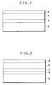
- Fig. 1 is a side view of an example of an optical recording medium of the present invention.
- Fig. 2 is a side view of another example of an optical recording medium of the present invention.
- the recording medium of the present invention comprises on a substrate a recording layer, a record-assisting layer and, optionally, a protecting layer, in this order from the substrate.
- the optical record-assisting layer in the recording medium of the present invention is composed of an elastic polymer cured by irradiation of a UV ray or an electron ray.
- the optical recording medium contains a radical scavenger which scavenges the radicals generated on curing the polymerizable component to prevent deterioration of the recording layer from being caused by the radicals.
- the record-assisting layer is composed of an elastic polymer cured by ionic polymerization reaction to prevent the sensitivity of the recording layer from lowering.
- the optical recording medium of the present invention comprises, as illustrated in Fig 1, a substrate 2, a recording medium 3, a record-assisting layer 4, and optionally a protecting layer 5.
- the record-assisting layer 4 is formed out of a high-molecular compound having rubber elasticity (hereinafter referred to as an elastic polymer), providing the recording medium with the contact-layer structure.
- the elastic polymer is formed by curing a polymerizable component with a UV ray or an electron ray.
- polymerizable component herein means a compound which gives a polymer by polymerization or crosslinking.
- the elastic polymer employed for forming the record-assisting layer 4 includes, for example, silicone rubbers which is curable according to the mechanisms shown by the formulas (1) to (3). (wherein "n” is an integer)
- the elastic polymer employed for forming the record-assisting layer 4 includes diene type liquid rubbers having a vinyl group in the molecular chain or at the end thereof, for example, as shown in the formula (4).
- x + y 1
- the formulas (1) to (4) exemplify the elastic polymers used for forming the record-assisting layer 4.
- the record-assisting layer 4 has preferably a hardness after cure in the range of from 2 to 70, more preferably from 3 to 60 according to JIS-K 6301 (or ASTM D2240), while the preferred polymerization degree or molecular weight cannot readily be shown.
- the radical polymerization initiator which is employed optionally in curing the polymerizable component, includes usual radical polymerization initiators such as acetophenones, e.g., dichloroacetophenone, trichloroacetopheneone, dialkoxyacetophenone, etc; benzophenone, Michler's ketone, benzylbenzoyl, benzoin ether, benzyldimetylketal, benzoyl benzoate, ⁇ -acyloxime esters, and the like.
- the polymerization initiator is used preferably in an amount of from 5/1000 to 5/100 by weight of the polymerizable component
- the recording layer 3 contains an organic coloring matter and a radical scavenger.
- the organic coloring matter includes cyanines, merocyanines, polymethines, phthalocyanines, naphthalocyanines, tetrahydrocholines, dioxazines, pyryliums, azulenes, anthraquinones, and the like.
- cyanines, merocyanines, polymethines, azulenes, phthalocyanines, and naphthalocyanines are highly effective in maintaining the recording sensivity of the recording layer 3 in combination with the record-assisting layer 4 composed of an elastic polymer.
- the effective radical scavenger which reacts readily with a radical to inhibit the progress of a radical chain reaction, includes phenols, quinones, amines, and the like.
- the phenols includes 2,6-di-t-butyl-p-cresol, butylated hydroxyanisole, 2,6-di-t-butyl-4-ethylphenol, stearyl- ⁇ -(3,5-di-t-butyl-4-hydroxyphenyl) propionate, 2,2′-methylene-bis-(4-methyl-6-t-butylphenol), 2,2′-methylene-bis-(4-ethyl-6-t-butylphenol), 4,4′-thiobis-(3-methyl-6-t-butylphenol), 4,4′-butylidene-bis-(3-methyl-6-t-butylphenol), 1,1,3-tris-(2-methyl-4-hydroxy-5-t-butylphenyl)butane, 1,3,5-trimethyl-2
- the quinones include hydroquinone, hydroquinone monomethyl ether, hydroxyhydroquinone, p-benzoquinone, and the like.
- the amines include N,N-diphenyl-p-phenylenediamine, N,N-di- ⁇ -naphthyl-p-phenylenediamine, phenyl-isopropyl-p-phenylenediamine, N-phenyl-N′-(1-methylheptyl)-p-phenylenediamine, and hindered amines.
- phenols as the radical scavenger in view of the low interaction thereof with the organic coloring matter forming the recording layer.
- the radical scavenger is not limited to these compounds in the present invention.
- the organic coloring matter is contained preferably in an amount of from 60 to 99.95 %, more preferably from 70 to 99.0 % by weight based on the recording layer 3. (hereinafter the percentage is based on weight).
- the radical scavenger is contained preferably in a weight ratio to the organic coloring matter of from 5/10000 to 40/100, more preferably from 1/1000 to 30/100. If the content of the radical scavenger is less than 5/10000, the radical scavenging effect is low, while if the content is higher than 40/100, it causes lower reflectance, lower recording sensitivity, or retardation of curing of the record-assisting layer.
- the radical scavenging compound may be dispersed uniformly in the recording layer 3.
- the radical scavenging compound is distributed at a higher concentration at the side of the record-assisting layer 4 than at the side of the substrate 2 in the recording layer 3 to scavenge radicals effectively.
- Such a nonuniform distribution of the concentration decreases the required amount of the radical scavenging compound, thereby preventing the decrease of the reflectivity of the recording layer 3.
- the content thereof is preferably in a ratio of from 5/10000 to 20/100, more preferably from 5/10000 to 10/100 by weight to the organic coloring matter.
- the record-assisting layer 4 is applied on the recording layer 3 and then the recording layer 3 is heated from the side of the substrate 2 at a temperature of from 70 to 140°C prior to the curing.
- the radical-scavenging compound migrates to the side of the record-assisting layer by heating because the radical-scavenging compound is more sublimable than the organic coloring matter.
- the recording layer 3 may contain optionally a stabilizing agent.
- This stabilizing agent includes metal chelate compound, particularly those which have a central metal such as Zn, Cu, Ni, Cr, Co, Mn, Pd, and Zr, and a multidentate ligand such as tetradentate ligands, e.g, N4, N2O2, N2S2O4, O2S2, and O4, etc. or their combinations; aromatic amines and diamines; nitrogen-containing aromatic compounds and onium salts thereof such as aminium salts, diimmonium salts, pyridinium salts, imidazolinium salts, and quinolium salts. Pyrylium salts which are salts of oxygen-containing aromatic compound are also useful.
- the stabilizing agent may be used singly or in combination of two or more thereof.
- the stabilizing agent is contained preferably in a ratio of from 1/100 to 50/100, more preferably from 10/100 to 40/100 by weight to the organic coloring matter.
- the optical recording medium described above contains a radical-scavenging compound in the recording layer 3.
- the radical-scavenging compound is not contained in the recording layer 3, and instead, a scavenging layer 1 which contains the radical-scavenging compound is provided between the recording layer 3 and the record-assisting layer 4 as illustrated in Fig. 2.
- the scavenging layer 1, which may be formed exclusively out of a radical-scavenging compound, is preferably composed of the radical-scavenging compound and a binder.
- the radical-scavenging compound is contained preferably in an amount of from 0;05 to 10 %, more preferably from 0.1 to 5 % in the scavenging layer 1.
- the binder to be contained in the scavenging layer 1 includes polymethyl methacrylates, polystyrenes, polyesters, polyurethanes, ethylenevinyl chloride copolymers, polyvinylidene chlorides, polyvinyl chlorides, polybutadienes, polyacetals, polyamides, polyimides, polyamidoimides, polyethylenes, polyethylene terephthalates, polycarbonates, polysulfones, polyvinyl alcohols, polyvinyl ethers, polyvinylbutyrals, polybutylene terephthalates, polypropylenes, nitrcelluloses, cellulose acetates, ethylcelluloses, polyvinyl acetates, ethylene-vinyl acetate copolymers, and vinyl chloride-vinyl acetate copolymers, and combinations of two or more thereof.
- the recording layer 3 may either contain or not contain a radical-scavenging compound.
- the recording layer 3 in Fig. 2 contains a radical-scavenging compound
- the recording layer 3 may be the same as the one described with reference to Fig. 1.
- the absence of the radical-scavenging compound in the recording layer 3 is preferred to avoid the fall of the reflectance of the recording layer.
- the content of the organic coloring matter in the recording layer 3 is preferably in the range of from 60 to 100 %,more preferably from 70 to 100 %.
- the recording layer 3 and the scavenging layer 1 provided separately may have either distinct interface or no distinct interface.
- the interface between the recording layer 3 and the scavenging layer 1 is not distinct, the components of the two layers are intermingled around the interface.
- the substrate 2 is preferably made of a light-transmissive material, including acrylic resins, polycarbonate resins, epoxy resins, polyolefin resins, polystyrene resins, and the like.
- the substrate 2 may have grooves for tracking (not shown in the drawing) on the surface.
- the protecting substrate 5, which is optionally provided, may be made of the same material as the substrate 2, the material including acrylic resins, polycarbonate resins, epoxy resins, polyolefin resins, and the like.
- the substrate 2 has a thickness preferably in the range of from 0.2 mm to 1.5 mm.
- the recording layer 3 has a thickness preferably in the range of from 500 to 2000 ⁇ , more preferably from 700 to 1700 ⁇ whether it contains a radical-scavenging compound or not.
- the scavenging layer 1 has a thickness preferably in the range of from 50 to 1500 ⁇ , more preferably from 100 to 1000 ⁇ .
- the record-assisting layer 4 has a thickness preferably in the range of from 3 to 50 ⁇ m, more preferably from 5 to 25 ⁇ m.
- the protecting substrate 5 has a thickness preferably in the range of from 50 ⁇ m to 1 mm.
- the optical recording medium of the present invention contains a record-assisting compound to scavenge the radicals generated in the record-assisting layer.
- the elastic polymer constituting the record-assisting compound is formed by ionic polymerization of a polymerizable component, no radical is produced and the radical-scavenging compound need not be contained in the optical recording medium.
- the record-assisting layer 4 of the optical recording medium of the present invention may be composed of an elastic polymer formed by ionic polymerization of a polymerizable component.
- the polymerizable component used in the ionic polymerization is preferably the one having an epoxy group.
- the elastic polymer formed by ionic polymerization of the polymerizable component includes silicone rubber, polybutadiene rubber, and the like.
- the preferred polymerizable component having an epoxy group are, for example, the substances represented by the formulas (5) to (12) below. In the formulas, l, m, and n are each an integer.
- the polymerizable component having an epoxy group in the present invention is polymerized through ionic polymerization with an ionic polymerization initiator which generates a Lewis acid on ultraviolet ray irradiation.
- the record-assisting layer 4 in this embodiment is formed by polymerization of a composition comprising a polymerizable component having an epoxy group and an ionic polymerization initiator.
- the ionic polymerization is initiated by a Lewis acid generated from an onium salt of the Lewis acid on ultraviolet ray irradiation, and after the irradiation is stopped, the polymerization progresses until the epoxy group is consumed nearly completely.
- Any onium salt of a Lewis acid may be used as a catalyst provided that it is capable of releasing a catalyst for initiating the ionic polymerization of a polymerizable component having an epoxy group on ultraviolet ray irradiation.
- the specific examples includes aromatic diazonium complexes of a halide, aromatic iodonium salt complexes, aromatic sulfonium salt complexes, aromatic ammonium salt complexes, and the like, which are disclosed in Macromolecule, Vol.10, No.6, pp.1307-1315; Photographic Science and Engineering Vol.18, p.387, and Japanese Patent Publication Nos. 52-14277, 52-14278, and 52-14279.
- Lewis acid anion of the onium salt includes the anions of BF4 ⁇ , PF6 ⁇ , AsF6 ⁇ , SbF6 ⁇ , SbCl6 ⁇ , SnCl62 ⁇ , FeCl42 ⁇ , and BiCl52 ⁇ . These Lewis acid anions are particularly preferred because the polymerizable component will polymerize rapidly owing to the high activity of the Lewis acid anion released on UV light irradiation or the like, and also because the recording layer is affected little thereby.
- the ionic polymerization initiator is employed in the same amount, relative to the epoxy component of the polymerizable component, as in the embodiment described by reference to Fig. 1.
- the substrate 2, the recording layer 3, and the protecting layer 5 may be the same as those employed in the aforementioned embodiment described by reference to Fig 1.
- a radical-scavenging compound need not be contained in the recording layer 3, and the organic coloring matter is contained preferably in an amount of from 60 to 100 %, more preferably from 70 to 100 % in the recording layer 3.
- the scavenging layer 1 need not be provided in this case.
- the recording layer 3 and the scavenging layer 1 may be formed by dissolving or dispersing the aforementioned materials respectively in a solvent and applying sequentially the solutions or dispersions onto the substrate 2.
- the solvent for dissolving the materials of the recording layer 3, such as an organic coloring matter and a stabilizing agent, is desired not to attack the substrate 2.
- Preferred solvents therefor include diacetone alcohol, cellosolve, 1-methoxy-2-propanol, and the like, and mixtures thereof with a small amount of a halogenated solvent.
- the solvent for dissolving the material of the scavenging layer 1 is desired not to dissolve the recording layer 3, but may slightly dissolve exclusively the surface of the recording layer 3.
- the solvent for the material of the scavenging layer 1 includes alcohols such as ethanol, isopropyl alcohol, amyl alcohol; cellosolves such as methylcellosolve and ethylcellosolve; n-hexane, benzene, xylene, and the like, depending on the material for the recording layer 3.
- the recording layer 3 may also be formed by vapor deposition.
- the record-assisting layer 4 may be formed by applying the aforementioned polymerizable component and optionally a polymerization initiator onto the recording layer 3 or the scavenging layer 1 in a desired thickness and subsequently exposing it to, for example, ultraviolet light irradiation.
- the source of the ultraviolet light is preferably a high-pressure mercury lamp, a metal halide lamp, and the like.
- the protecting substrate 5 which is optionally provided may be formed by lamination of a film of the aforementioned material.
- a UV-curable resin (STM401, made by Dainippon Ink and Chemicals Inc.) was filled between an extrusion-molded polycarbonate base plate of 0.4 mm thick and a stamper having predetermined grooves, and was cured by irradiation of a UV ray to provide a substrate having grooves of 3 ⁇ m in breadth, 12 ⁇ m in pitch, and 3000 ⁇ in depth (according to a so-called 2P process).
- a solution in dichloroethane of the organic coloring matter and the radical-scavenging compound shown in Table 1 was applied by bar coating to provide a recording layer of 1000 ⁇ thick.
- the concentration of a mixture of the organic coloring matter and the radical-scavenging compound was 2.0 %, the mixing ratio thereof being shown in Table 1.
- the UV-curable silicone rubber was applied in a thickness of 10 ⁇ m by roll coating, and subsequently the applied UV-curable silicone rubber was cured by irradiation of an ultraviolet ray from a high-pressure mercury lamp (160 W/cm) from a distance of 15 cm for 30 seconds in a nitrogen atmosphere to form a record-assisting layer.
- a high-pressure mercury lamp 160 W/cm
- a polycarbonate film of 0.3 mm thick was bonded with an ethylene-vinyl acetate copolymer type of hot-melt adhesive (Hirodine 7580, made by Hirodine Kogyo K.K.) by means of a roll laminator at a bonding temperature of 120°C to provide a protective substrate.
- Hirodine 7580 made by Hirodine Kogyo K.K.
- the resulting medium was cut into card-shaped pieces of 85.7 mm in length and 54.0 mm in breadth, thus providing optical cards of the optical recording medium of the present invention.
- the substrate employed was the same as the one employed in Example 1.
- the organic coloring matter [I], [II], or [III], the radical-scavenging compound, and the stabilizing agent having the structure of the formula [IV] or [V] below were dissolved in dichloroethane, and the resulting solution was applied onto the face of the grooves of the substrate by bar coating to provide a recording layer of 1000 ⁇ thick.
- the concentration of a mixture of the organic coloring matter, the radical-scavenging compound, and the stabilizing agent in the dichloroethane solution was 2.0 %.
- the mixing ratios of the radical-scavenging compound and the stabilizing agent to the organic coloring matter are shown in Table 2.
- a record-assisting layer was formed out of a UV-curable silicone rubber shown in Table 2 in the same manner as in Example 1.
- Example 2 Further on this record-assisting layer, the same protecting substrate as in Example 1 was provided. Finally the resulting recording medium was cut into pieces in the same manner as in Example 1 to prepare optical cards of the present invention.
- the UV-curable silicone rubber shown in Table 3 was applied on the resulting recording layer.
- the silicone rubber was heated from the substrate side at 90°C for 2 minutes prior to the curing by UV ray irradiation.
- Example 2 Subsequently in the same manner as in Example 1, the silicone rubber was cured to form a protecting substrate, and further the resulting recording medium was cut into card-shaped pieces, thereby providing optical cards of the present invention.
- the substrate employed was the same as the one employed in Example 1.
- the aforementioned organic coloring matter [I], [II], or [III], and the aforementioned stabilizing agent of the formula [IV] or [V] were dissolved in dichloroethane in the combination and the ratio shown in Table 4, and the solution was applied onto the face of the grooves of the substrate, by bar coating to provide a recording layer of 1000 ⁇ thick.
- the concentration of a mixture of the organic coloring matter and the stabilizing agent in the dichloroethane solution was 2.0 %.
- the radical-scavenging compound shown in Table 4 was dissolved or dispersed in xylene at a concentration of 5.0 % , and was applied onto the above recording layer to provide a scavenging layer of 300 ⁇ thick.
- a record-assisting layer was formed from a UV-curable silicone rubber shown in Table 4 in the same manner as in Example 1.
- Example 2 Further on this record-assisting layer, the same protecting substrate as in Example 1 was provided. Finally the resulting recording medium was cut into pieces in the same manner as in Example 1 to prepare optical cards of the present invention.
- the radical-scavenging compound and the binder was dissolved or dispersed in xylene in the combination and the blending ratio shown in Table 5, and was applied onto the above recording layer to provide a scavenging layer of 1000 ⁇ thick.
- the concentration of a mixture of the radical-scavenging compound and the binder in the xylene solution was 5.0 %.
- a record-assisting layer was formed out of a UV-curable silicone rubber shown in Table 5 in the same manner as in Example 1.
- Example 2 Further on this record-assisting layer, the same protecting substrate as the one in Example 1 was provided. Finally the resulting recording medium was cut into pieces in the same manner as in Example 1 to prepare optical cards of the present invention.
- the substrate employed was the same as the one employed in Example 1.
- the aforementioned organic coloring matter [I], [II], or [III] was dissolved in dichloroethane in the combination and the ratio shown in Table 6, and the solution was applied onto the face of the grooves of the aforementioned substrate by bar coating to provide a recording layer of 1000 ⁇ thick.
- the concentration of a mixture of the organic coloring matter and the stabilizing agent in the dichloroethane solution was 2.0 %.
- the mixture of the polymerizable component and the ionic polymerization initiator as shown in Table 6 was applied by means of a roll coater in a thickness of 10 ⁇ m, and the applied polymerizable component was cured by irradiation of an ultraviolet ray from a high-pressure mercury lamp at 160 w/cm at a distance of 15 cm for 30 seconds, thus forming a record-assisting layer.
- the mixing ratio of the polymerizable component to the ionic polymerization initiator was 95 to 5 by weight.
- Example 2 Further on this record-assisting layer, the same protecting substrate as the one in Example 1 was provided. Finally the resulting recording medium was cut into pieces in the same manner as in Example 1 to prepare optical cards of the present invention.
- a UV-curable resin (STM401, made by Dainippon Ink and Chemicals, Inc.) was filled between an extrusion-molded polycarbonate base plate of 1.2 mm thick and a stamper having predetermined grooves, and was cured by irradiation of a UV ray, to provide a substrate having grooves of 0.6 ⁇ m in width, 1.6 ⁇ m in pitch, and 0.1 ⁇ m in depth (according to a so-called 2P process).
- the organic coloring matter [I], [VI], or [VII] as shown in Table 7 was applied in the same manner as in Example 33 to provide a recording layer of 1000 ⁇ thick.
- Example 33 Onto the recording layer thus formed, a mixture of the polymerizable component and the ionic polymerization initiator was applied in the same manner as in Example 33, and the polymerizable component was cured under the same conditions as in Example 33 to provide a record-assisting layer.
- the mixing ratio of the polymerizable component to the ionic polymerization initiator was the same as in Example 33.
- Example 2 Further on the record-assisting layer, the same protecting layer as that of Example 1 was provided. Finally, the resulting recording medium was cut into disks of 86 mm in diameter to prepare optical disks of the present invention.
- Example 2 The same substrate was employed as the one employed in Example 1. Onto the face of the grooves the organic coloring matter [I], [II], or [III] and the stabilizing agent [IV] or [V] as mentioned above were applied in the combination and the mixing ratio shown in Table 8 in the same manner as in Example 1 to provide a recording layer of 1000 ⁇ thick. This recording layer contained no radical-scavenging compound.
- a record-assisting layer of the UV-curable silicone rubber shown in Table 8 was provided in the same manner as in Example 1.
- the UV-curable silicone rubbers shown in Table 8 are curable by a radical chain reaction.
- Example 2 the same protecting substrate as the one in Example 1 was provided. Finally the resulting recording medium was cut in the same manner as in Example 1 to prepare optical cards.
- the substrate employed was the same as the one employed in Example 43.
- the organic coloring matter [I], [VI], or [VII] as mentioned above was applied in the same manner as in Example 33 to provide a recording layer of 1000 ⁇ thick.
- This recording layer contained no radical-scavenging compound.
- a record-assisting layer of the UV-curable silicone rubber shown in Table 9 was provided in the same manner as in Example 1.
- the UV-curable silicone rubbers shown in Table 9 are curable by a radical chain reaction.
- Example 43 the same protecting substrate as the one in Example 1 was provided. Finally the resulting recording medium was cut in the same manner as in Example 43 to prepare optical disks of 86 mm in diameter.
- optical cards of Examples 1 to 42, the optical disks of Examples of 43 to 50, the optical cards of Comparative Examples 1 to 3, and the optical disks of Comparative Examples 4 to 8 were subjected to measurement of the reflectance at the wavelength of 830 nm by introducing light from the side of the substrate by means of a spectrophotometer U-3400 made by Hitachi, Ltd. The measured reflectances are shown in Tables 10 to 13.
- the optical cards of Examples 1 to 42 and Comparative Examples 1 to 3 were tested for recording and reproduction at a feed rate of 0.06 m/sec by use of a semiconductor laser at a wavelength of 830 nm.
- the recording was conducted at a recording power of 3.5 mW and pulse width of 50 ⁇ sec, and the reproduction was conducted with a reproduction power of 0.2 mW.
- the record-reproduction contrast was calculated from the equation [A] below. The obtained values of the record-reproduction contrast are shown in Table 10 and Table 11.
- Record-reproduction contrast [(Reflectance of non-recorded portion) - (Reflectance of recorded portion)] / (Reflectance of non-recorded portion)
- the optical disks of Examples 43 to 50 and Comparative Examples 4 to 8 were tested for recording and reproduction at a rotation rate of 1800 rpm at a wavelength of 830 nm with a semiconductor laser, and the values of C/N were measured.
- the recording was conducted at a recording power of 8.0 mW at a recording frequency of 3 MHz, and the reproduction was conducted at a reproduction power of 0.5 mW.
- the obtained C/N values are shown in Table 12 and Table 13.
- the recording sensitivity of a recording layer of an optical recording medium is maintained high by incorporating a radical-scavenging compound or by employing a record-assisting layer which is curable by ionic polymerization.
- the optical recording medium has high recording sensitivity, particularly in the case where a scavenging layer containing a radical-scavenging compound is provided between the recording layer and the record-assisting layer.
- the optical recording medium has high recording sensitivity in the case where the radical-scavenging compound in the recording layer is contained in a higher concentration at the record-assisting layer side in the recording layer.
Landscapes
- Optical Record Carriers And Manufacture Thereof (AREA)
- Thermal Transfer Or Thermal Recording In General (AREA)
Applications Claiming Priority (4)
| Application Number | Priority Date | Filing Date | Title |
|---|---|---|---|
| JP42447/91 | 1991-02-16 | ||
| JP4244791 | 1991-02-16 | ||
| JP87392/91 | 1991-03-28 | ||
| JP8739291 | 1991-03-28 |
Publications (3)
| Publication Number | Publication Date |
|---|---|
| EP0503774A2 true EP0503774A2 (fr) | 1992-09-16 |
| EP0503774A3 EP0503774A3 (en) | 1993-01-20 |
| EP0503774B1 EP0503774B1 (fr) | 1997-05-14 |
Family
ID=26382138
Family Applications (1)
| Application Number | Title | Priority Date | Filing Date |
|---|---|---|---|
| EP19920301253 Expired - Lifetime EP0503774B1 (fr) | 1991-02-16 | 1992-02-14 | Milieu d'enregistrement optique |
Country Status (3)
| Country | Link |
|---|---|
| US (1) | US5354590A (fr) |
| EP (1) | EP0503774B1 (fr) |
| DE (1) | DE69219649T2 (fr) |
Cited By (2)
| Publication number | Priority date | Publication date | Assignee | Title |
|---|---|---|---|---|
| EP0689202A3 (fr) * | 1994-06-22 | 1996-02-07 | Pioneer Electronic Corp | Milieu d'enregistrement optique |
| EP0833316A3 (fr) * | 1996-09-27 | 1998-11-04 | Eastman Kodak Company | Méthode pour obtenir un intervalle de conformalités pour des couches d'enregistrement |
Families Citing this family (3)
| Publication number | Priority date | Publication date | Assignee | Title |
|---|---|---|---|---|
| KR100313567B1 (ko) * | 1994-02-28 | 2001-12-28 | 윤종용 | 유기광기록매체및그의재기록방지방법 |
| JP2002269812A (ja) * | 2001-03-14 | 2002-09-20 | Sony Corp | 光学記録媒体およびその製造方法 |
| FR2848013B1 (fr) * | 2002-12-03 | 2005-01-07 | Commissariat Energie Atomique | Support d'enregistrement optique irreversible a base d'un alliage de tellure et de zinc. |
Family Cites Families (25)
| Publication number | Priority date | Publication date | Assignee | Title |
|---|---|---|---|---|
| US3760958A (en) * | 1972-05-22 | 1973-09-25 | Kearney & Trecker Corp | Clamping tool changer mechanism and actuating mechanism for a machine tool |
| GB1516511A (en) * | 1974-05-02 | 1978-07-05 | Gen Electric | Curable epoxide compositions |
| JPS5214277A (en) * | 1975-07-25 | 1977-02-03 | Nippon Steel Corp | Panel positioning apparatus |
| JPS5214278A (en) * | 1975-07-25 | 1977-02-03 | Nippon Steel Corp | Panel assemly process |
| US4315269A (en) * | 1977-08-29 | 1982-02-09 | Rca Corporation | Thick protective overcoat layer for optical video disc |
| JPS5770694A (en) * | 1980-10-20 | 1982-05-01 | Toshiba Corp | Information-recording member |
| JPS58125248A (ja) * | 1982-01-22 | 1983-07-26 | Fujitsu Ltd | 光記録媒体 |
| JPS58203095A (ja) * | 1982-05-24 | 1983-11-26 | Fujitsu Ltd | 光情報記録媒体 |
| JPS60117430A (ja) * | 1983-11-29 | 1985-06-24 | Toshiba Corp | 光ディスク |
| DE3503995A1 (de) * | 1984-02-06 | 1985-08-08 | Ricoh Co., Ltd., Tokio/Tokyo | Optischer informationsaufzeichnungstraeger |
| JPS61137243A (ja) * | 1985-07-10 | 1986-06-24 | Dainippon Printing Co Ltd | 光カ−ド |
| JPS6228291A (ja) * | 1985-07-31 | 1987-02-06 | Olympus Optical Co Ltd | 光学的情報記録媒体 |
| JPS62283121A (ja) * | 1986-05-30 | 1987-12-09 | Matsushita Electric Ind Co Ltd | 光学用樹脂成形材料の製造方法 |
| JPS632223A (ja) * | 1986-06-21 | 1988-01-07 | Toshiba Corp | ブラウン管パネル処理装置 |
| JPS6342333A (ja) * | 1986-08-08 | 1988-02-23 | Toshiba Corp | 鉄心の焼鈍方法 |
| US4892606A (en) * | 1986-08-28 | 1990-01-09 | Canon Kabushiki Kaisha | Optical recording medium having space therein and method of manufacturing the same |
| JPS63200339A (ja) * | 1987-02-12 | 1988-08-18 | Canon Inc | 情報記録媒体 |
| US4944981A (en) * | 1987-02-25 | 1990-07-31 | Canon Kabushiki Kaisha | Optical recording medium |
| US4921780A (en) * | 1987-06-12 | 1990-05-01 | Canon Kabushiki Kaisha | Optical recording medium |
| US4965178A (en) * | 1987-09-12 | 1990-10-23 | Canon Kabushiki Kaisha | Optical recording medium |
| EP0404951B1 (fr) * | 1988-07-01 | 1996-04-24 | Sony Corporation | Support d'enregistrement optique et procede de production de ce support |
| JPH0267179A (ja) * | 1988-09-01 | 1990-03-07 | Matsushita Electric Ind Co Ltd | 書換え可能な光記録媒体およびその消去法 |
| JP2897773B2 (ja) * | 1988-10-28 | 1999-05-31 | ティーディーケイ株式会社 | 光記録再生方法 |
| US5009987A (en) * | 1988-11-16 | 1991-04-23 | Canon Kabushiki Kaisha | Optical recording medium containing IR-ray absorptive compound |
| JP2551474B2 (ja) * | 1988-11-28 | 1996-11-06 | キヤノン株式会社 | 光記録媒体およびその製造方法 |
-
1992
- 1992-02-14 US US07/835,343 patent/US5354590A/en not_active Expired - Fee Related
- 1992-02-14 DE DE69219649T patent/DE69219649T2/de not_active Expired - Fee Related
- 1992-02-14 EP EP19920301253 patent/EP0503774B1/fr not_active Expired - Lifetime
Cited By (3)
| Publication number | Priority date | Publication date | Assignee | Title |
|---|---|---|---|---|
| EP0689202A3 (fr) * | 1994-06-22 | 1996-02-07 | Pioneer Electronic Corp | Milieu d'enregistrement optique |
| US5635268A (en) * | 1994-06-22 | 1997-06-03 | Pioneer Electronic Corporation | Optical recording medium |
| EP0833316A3 (fr) * | 1996-09-27 | 1998-11-04 | Eastman Kodak Company | Méthode pour obtenir un intervalle de conformalités pour des couches d'enregistrement |
Also Published As
| Publication number | Publication date |
|---|---|
| US5354590A (en) | 1994-10-11 |
| DE69219649D1 (de) | 1997-06-19 |
| DE69219649T2 (de) | 1997-10-23 |
| EP0503774B1 (fr) | 1997-05-14 |
| EP0503774A3 (en) | 1993-01-20 |
Similar Documents
| Publication | Publication Date | Title |
|---|---|---|
| US7704643B2 (en) | Holographic recording medium with control of photopolymerization and dark reactions | |
| US5419939A (en) | Optical recording disk | |
| EP0385341B1 (fr) | Milieu d'enregistrement optique | |
| US20100266936A1 (en) | Photosensitive composition for volume hologram recording, photosensitive medium for volume hologram recording and volume hologram | |
| JP2657597B2 (ja) | 光記録ディスク | |
| WO2005032814A1 (fr) | Article a revetement dur, composition durcissable et support d'enregistrement d'informations | |
| KR100439246B1 (ko) | 광디스크용 방사선-경화성 코팅재 및 상기 코팅재에 의해코팅된 광디스크 | |
| US20080013138A1 (en) | Hologram recording material, hologram recording medium and hologram recording method | |
| EP0503774A2 (fr) | Milieu d'enregistrement optique | |
| US20050185232A1 (en) | Volume hologram recording photosensitive composition and its use | |
| DE69833318T2 (de) | Optisches aufzeichnungsmedium | |
| DE69323972T2 (de) | Optisches Aufzeichnungsmedium | |
| JP2510803B2 (ja) | 光記録媒体 | |
| DE69838075T2 (de) | Optisches aufzeichnungsmedium und herstellungsverfahren dafür | |
| US20120251927A1 (en) | Hologram-recording medium | |
| KR100577905B1 (ko) | 광기록매체의 제조방법 및 광기록매체 | |
| JP3004289B2 (ja) | 光記録媒体およびその製造方法 | |
| JP2901417B2 (ja) | 光記録ディスクの製造方法 | |
| JP3266754B2 (ja) | 書き込み可能な光情報記録媒体とその製造方法 | |
| JP3199490B2 (ja) | 光記録ディスク | |
| JP2000063711A (ja) | 光輝顔料およびその製造方法 | |
| JPH07104643A (ja) | ホログラム記録材料及びホログラム記録用媒体 | |
| JPH0447632B2 (fr) | ||
| JP2715192B2 (ja) | 波長多重光記録媒体 | |
| JP3007101B2 (ja) | 書き替え可能な光記録媒体および製造法 |
Legal Events
| Date | Code | Title | Description |
|---|---|---|---|
| PUAI | Public reference made under article 153(3) epc to a published international application that has entered the european phase |
Free format text: ORIGINAL CODE: 0009012 |
|
| AK | Designated contracting states |
Kind code of ref document: A2 Designated state(s): BE DE FR GB IT NL |
|
| PUAL | Search report despatched |
Free format text: ORIGINAL CODE: 0009013 |
|
| AK | Designated contracting states |
Kind code of ref document: A3 Designated state(s): BE DE FR GB IT NL |
|
| 17P | Request for examination filed |
Effective date: 19930609 |
|
| 17Q | First examination report despatched |
Effective date: 19931001 |
|
| GRAG | Despatch of communication of intention to grant |
Free format text: ORIGINAL CODE: EPIDOS AGRA |
|
| GRAH | Despatch of communication of intention to grant a patent |
Free format text: ORIGINAL CODE: EPIDOS IGRA |
|
| GRAH | Despatch of communication of intention to grant a patent |
Free format text: ORIGINAL CODE: EPIDOS IGRA |
|
| ITF | It: translation for a ep patent filed | ||
| GRAA | (expected) grant |
Free format text: ORIGINAL CODE: 0009210 |
|
| AK | Designated contracting states |
Kind code of ref document: B1 Designated state(s): BE DE FR GB IT NL |
|
| PG25 | Lapsed in a contracting state [announced via postgrant information from national office to epo] |
Ref country code: NL Free format text: LAPSE BECAUSE OF FAILURE TO SUBMIT A TRANSLATION OF THE DESCRIPTION OR TO PAY THE FEE WITHIN THE PRESCRIBED TIME-LIMIT Effective date: 19970514 Ref country code: FR Effective date: 19970514 Ref country code: BE Effective date: 19970514 |
|
| REF | Corresponds to: |
Ref document number: 69219649 Country of ref document: DE Date of ref document: 19970619 |
|
| NLV1 | Nl: lapsed or annulled due to failure to fulfill the requirements of art. 29p and 29m of the patents act | ||
| EN | Fr: translation not filed | ||
| PLBE | No opposition filed within time limit |
Free format text: ORIGINAL CODE: 0009261 |
|
| 26N | No opposition filed | ||
| REG | Reference to a national code |
Ref country code: GB Ref legal event code: IF02 |
|
| PGFP | Annual fee paid to national office [announced via postgrant information from national office to epo] |
Ref country code: DE Payment date: 20050420 Year of fee payment: 14 |
|
| PGFP | Annual fee paid to national office [announced via postgrant information from national office to epo] |
Ref country code: GB Payment date: 20060131 Year of fee payment: 15 |
|
| PGFP | Annual fee paid to national office [announced via postgrant information from national office to epo] |
Ref country code: IT Payment date: 20060228 Year of fee payment: 15 |
|
| PG25 | Lapsed in a contracting state [announced via postgrant information from national office to epo] |
Ref country code: DE Free format text: LAPSE BECAUSE OF NON-PAYMENT OF DUE FEES Effective date: 20060901 |
|
| GBPC | Gb: european patent ceased through non-payment of renewal fee |
Effective date: 20070214 |
|
| PG25 | Lapsed in a contracting state [announced via postgrant information from national office to epo] |
Ref country code: GB Free format text: LAPSE BECAUSE OF NON-PAYMENT OF DUE FEES Effective date: 20070214 |
|
| PG25 | Lapsed in a contracting state [announced via postgrant information from national office to epo] |
Ref country code: IT Free format text: LAPSE BECAUSE OF NON-PAYMENT OF DUE FEES Effective date: 20070214 |