EP0503929A2 - Laser mit temperaturkontrolliertem oberwellenerzeugenden Kristall - Google Patents
Laser mit temperaturkontrolliertem oberwellenerzeugenden Kristall Download PDFInfo
- Publication number
- EP0503929A2 EP0503929A2 EP92302095A EP92302095A EP0503929A2 EP 0503929 A2 EP0503929 A2 EP 0503929A2 EP 92302095 A EP92302095 A EP 92302095A EP 92302095 A EP92302095 A EP 92302095A EP 0503929 A2 EP0503929 A2 EP 0503929A2
- Authority
- EP
- European Patent Office
- Prior art keywords
- crystal
- temperature
- light
- resonator
- laser
- Prior art date
- Legal status (The legal status is an assumption and is not a legal conclusion. Google has not performed a legal analysis and makes no representation as to the accuracy of the status listed.)
- Ceased
Links
Images
Classifications
-
- G—PHYSICS
- G02—OPTICS
- G02F—OPTICAL DEVICES OR ARRANGEMENTS FOR THE CONTROL OF LIGHT BY MODIFICATION OF THE OPTICAL PROPERTIES OF THE MEDIA OF THE ELEMENTS INVOLVED THEREIN; NON-LINEAR OPTICS; FREQUENCY-CHANGING OF LIGHT; OPTICAL LOGIC ELEMENTS; OPTICAL ANALOGUE/DIGITAL CONVERTERS
- G02F1/00—Devices or arrangements for the control of the intensity, colour, phase, polarisation or direction of light arriving from an independent light source, e.g. switching, gating or modulating; Non-linear optics
- G02F1/35—Non-linear optics
- G02F1/37—Non-linear optics for second-harmonic generation
-
- G—PHYSICS
- G02—OPTICS
- G02F—OPTICAL DEVICES OR ARRANGEMENTS FOR THE CONTROL OF LIGHT BY MODIFICATION OF THE OPTICAL PROPERTIES OF THE MEDIA OF THE ELEMENTS INVOLVED THEREIN; NON-LINEAR OPTICS; FREQUENCY-CHANGING OF LIGHT; OPTICAL LOGIC ELEMENTS; OPTICAL ANALOGUE/DIGITAL CONVERTERS
- G02F1/00—Devices or arrangements for the control of the intensity, colour, phase, polarisation or direction of light arriving from an independent light source, e.g. switching, gating or modulating; Non-linear optics
- G02F1/35—Non-linear optics
- G02F1/3501—Constructional details or arrangements of non-linear optical devices, e.g. shape of non-linear crystals
- G02F1/3503—Structural association of optical elements, e.g. lenses, with the non-linear optical device
-
- G—PHYSICS
- G02—OPTICS
- G02F—OPTICAL DEVICES OR ARRANGEMENTS FOR THE CONTROL OF LIGHT BY MODIFICATION OF THE OPTICAL PROPERTIES OF THE MEDIA OF THE ELEMENTS INVOLVED THEREIN; NON-LINEAR OPTICS; FREQUENCY-CHANGING OF LIGHT; OPTICAL LOGIC ELEMENTS; OPTICAL ANALOGUE/DIGITAL CONVERTERS
- G02F1/00—Devices or arrangements for the control of the intensity, colour, phase, polarisation or direction of light arriving from an independent light source, e.g. switching, gating or modulating; Non-linear optics
- G02F1/35—Non-linear optics
- G02F1/353—Frequency conversion, i.e. wherein a light beam is generated with frequency components different from those of the incident light beams
- G02F1/3542—Multipass arrangements, i.e. arrangements to make light pass multiple times through the same element, e.g. using an enhancement cavity
-
- G—PHYSICS
- G02—OPTICS
- G02F—OPTICAL DEVICES OR ARRANGEMENTS FOR THE CONTROL OF LIGHT BY MODIFICATION OF THE OPTICAL PROPERTIES OF THE MEDIA OF THE ELEMENTS INVOLVED THEREIN; NON-LINEAR OPTICS; FREQUENCY-CHANGING OF LIGHT; OPTICAL LOGIC ELEMENTS; OPTICAL ANALOGUE/DIGITAL CONVERTERS
- G02F1/00—Devices or arrangements for the control of the intensity, colour, phase, polarisation or direction of light arriving from an independent light source, e.g. switching, gating or modulating; Non-linear optics
- G02F1/35—Non-linear optics
- G02F1/353—Frequency conversion, i.e. wherein a light beam is generated with frequency components different from those of the incident light beams
- G02F1/3544—Particular phase matching techniques
- G02F1/3546—Active phase matching, e.g. by electro- or thermo-optic tuning
Definitions
- This invention relates generally to laser systems and more particularly to laser systems which use nonlinear crystals.
- GaAlAs gallium-aluminum-arsenide diode laser which generates light in the near infrared range (856 nm in wavelength).
- GaAlAs gallium-aluminum-arsenide
- the light from the laser diode is focussed onto a spot on the optical disk in order to record each bit of data.
- the spot size is approximately equal to _/(2*(N.A.)), where _ is the wavelength of the light and N.A. is the numerical aperture of the focusing lens.
- the N.A. is approximately 0.5 and the resulting spot size is 856 nm in diameter.
- SHG second harmonic generation
- KNbO3 potassium niobate
- SH second harmonic
- This SHG technique is described in articles by M.K. Chun, et al., Applied Physics Letters , Vol. 55, p. 218, July 17, 1989; and P. Gunter, et al., Applied Physics Letters , Vol. 35, p. 461, September 15, 1979.
- diode laser's output power is low, techniques to improve the second harmonic generation efficiency are required in order to produce a useful and efficient laser system.
- a laser system comprising a laser for providing an input beam of light at a first frequency, a non-linear crystal resonator for receiving the input beam and resonating along a predetermined beam path, the resonator being effective to convert the light at the first frequency to light at a second frequency, a beam splitter for receiving the second frequency light and a temperature controller to control the temperature of the non-linear crystal resonator characterised in that the resonator incorporates a crystal having a non-critical phase matching axis at an angle to the predetermined beam path and the temperature controller includes a sensor to receive the second frequency beam of light, the sensor being capable of sensing changes in the duration of the second frequency light caused by variation in temperature of the resonator crystal, the temperature controller including means to adjust the temperature of the crystal in response to an output from the sensor.
- a method for crystal temperature control comprising the steps of: generating a radiation beam; passing the radiation beam through a nonlinear crystal along a beam path which is slightly offset from a noncritical phase matching axis of the crystal; detecting an angle at which the radiation beam exits the crystal ; and adjusting the temperature of the crystal responsive to the measured angle.
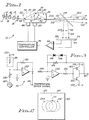
- Fig. 1 shows a laser system of the present invention and is designated by the general reference number 10.
- System 10 detects the angular change of the output beam from a nonlinear resonator in order to generate a temperature error signal.
- Laser diode 12 may be a gallium-aluminum-arsenide (GaAlAs) laser diode which generates a light beam 14 at approximately 856 nm wavelength (near infrared). Beam 14 is also referred to as the fundamental frequency light beam. Although light is used in the preferred embodiment, other types of electromagnetic radiation may also be used.
- GaAlAs gallium-aluminum-arsenide
- Beam 14 is collimated by a lens 15 and passes through a circularizing prism 16 and a Faraday Isolator 17. The light is then coupled by a lens 18 into an optical resonator 20.
- Resonator 20 is a three sided ring resonator having a plurality of mirror surfaces 22, 24 and 26. A total internal reflectance surface may alternatively be used in place of mirror 24.
- the frequency of the laser diode 12 is matched to the resonance frequency of resonator 20.
- a nonlinear crystal 30 is located within resonator 22. In a preferred embodiment, the nonlinear crystal 30 is made of potassium (KNbO3).
- Mirror 22 has a reflectivity R1 for the fundamental frequency light beam 14 from laser 12.
- the reflectivity R1 is chosen such that resonator 20 will impedance match the light beam 14 from laser 12 so that the light coupled into resonator 20 is maximized.
- impedance matching is given in the article by W.J. Kozlovsky, et al., "Efficient Second Harmonic Generation of a Diode Laser Pumped Cd Nd:YAG Laser," IEEE Journal of Quantum Electronics , Vol. QE-24, No. 6, p. 913, (1988).
- Mirror 24 has a reflectivity of approximately one hundred percent (100%) at the fundamental frequency.
- Mirror 26 has a reflectivity of greater than or equal to ninety-five percent (95%) for fundamental frequency light and a transmission of greater than eighty percent (80%) for SH light.
- Mirrors 22, 24 and 26 are made of a multi-layer dielectric coating as is known in the art.
- the layers may be made of SiO2 and TiO2 in alternating layers. These dielectric coatings may be deposited directly on the surface of crystal 30 or alternatively separate mirrors may be used.
- Resonator 20 has an internal beam path 32 which comprises a primary leg beam path 34 and two secondary leg beam paths 36 and 38.
- Crystal 30 has A, B and C crystallographic axes as are known in the art. In Fig. 1 the B axis is shown as being perpendicular to the paper. Crystal 30 is positioned within resonator 20 such that the A axis (noncritical phase matching axis) is offset at a slight angle 40 from the path 34. In a preferred embodiment the angle 40 is in the range of approximately 0.1 to 5 degrees, although operation is possible with other angles.
- the A axis is the noncritical phase matching axis.
- Other wavelengths and other nonlinear crystals may have different noncritical phase matching axes.
- the noncritical phase matching axis should be offset at a slight angle from the beam path.
- Resonator 20 outputs a SH light beam 50 along an axis 52.
- a beamsplitter 54 is located along the path of beam 50.
- a portion of beam 50 is reflected by beamsplitter 54 as a beam 56 and a remaining portion of beam 50 continues through beamsplitter 54 as a beam 58.
- Beam 56 falls upon a photodetector 60.
- Photodetector 60 has a first section 62 and a second section 64. See Fig. 2.
- the output from sections 62 and 64 are connected to a differential amplifier 66.
- the output of differential amplifier 66 is connected to a temperature controller 70.
- Temperature controller 70 is connected to a crystal temperature element 80 and a temperature monitor 86.
- element 80 is a thermo-electric cooler (also called a Peltier element) and temperature monitor 86 is a thermistor.
- a resistive heater may also be used as element 80.
- the crystal temperature element 80 and temperature monitor 86 are attached to crystal 30.
- Fig. 3 is a circuit diagram of a temperature controller 70 of system 10.
- a positive voltage source 120 is connected to thermistor 86.
- Thermistor 86 is connected to an amplifier 122.
- a current source 124 is connected to a variable resistor 126.
- Resistor 126 is connected to amplifier 122.
- a gain resistor 130 is connected parallel to amplifier 122.
- the output of amplifier 122 and the output of amplifier 66 are connected to resistor 140.
- Resistor 140 is connected to an amplifier 142, a variable resistor 144, and a pair zener diodes 146 and 148.
- the output of amplifier 142 is connected to a resistor 150.
- a pair of power transistors 160 and 162 are connected to resistor 150.
- a positive voltage source 166 is connected to transistor 160 and a negative voltage source 168 is connected to transistor 162.
- Transistors 160 and 162, variable resistor 144 and diode 148 are all connected to crystal temperature element 80.
- temperature controller 70 is shown as the preferred embodiment, other types of temperature controllers may also be used.
- Laser diode 12 produces a polarized beam 14 of fundamental frequency light.
- the light passes through lens 15, prism 16 and Faraday Isolator 17.
- Lens 18 focuses beam 14 through mirror 22 of resonator 20.
- the fundamental frequency light then travels around beam path 32 inside resonator 20.
- the plane of polarization of the fundamental frequency light is parallel to the B axis of crystal 30.
- Lens 16 focuses the light so that the fundamental frequency light entering resonator 20 is spatially mode matched to the fundamental frequency light which is already traveling around path 32. Spatial mode matching is discussed in the article "Laser Beams and Resonators,” Applied Optics , Vol. 5, pp. 1550-1567, October 1966.
- Fundamental frequency light within resonator 20 is converted to SH light by repeated passes through crystal 30.
- the SH light 50 readily exits through mirror 26.
- the second harmonic generation process will produce the maximum second harmonic light when crystal 30 is maintained at the critical phase matching temperature.
- the SH light 50 exits resonator 20 along axis 52.
- a portion of beam 50 is reflected by beamsplitter 54 as beam 56.
- Beam 56 will fall exactly on the center of photodetector 60 when the crystal 30 is at the critical phase matching temperature. See Fig. 2.
- the output of both detectors 62 and 64 will then be equal and amplifier 66 will output a zero error signal to temperature controller 70.
- the SH light will exit resonator 30 as a beam 200 along an axis 202.
- Axis 202 is oriented at a slight angle above axis 52.
- a portion of beam 200 is reflected by beamsplitter 54 as a beam 204.
- Beam 204 falls on photodetector 60 with the majority of the beam on section 62.
- Amplifier 66 will generate a positive temperature error signal.
- Temperature controller 70 will cause element 80 to cool crystal 30.
- the SH light will exit resonator 30 as a beam 210 along an axis 212.
- a portion of beam 210 is reflected by beamsplitter 54 as a beam 216.
- Beam 216 falls on photodetector 60 with a majority of the beam on section 64.
- Amplifier 66 will generate a negative temperature error signal.
- the temperature controller 70 will cause element 80 to heat crystal 30.
- phasematching temperature (To) optimum phasematching will occur along axis 34 and a maximum amount of SH light is output along axis 52.
- the direction for optimum phasematching is rotated slightly away from axis 34. Due to the fact that axis 34 is slightly offset from the noncritical phasematching axis A, the phasematching direction will lie on one side of axis 34 for temperatures above To and on the other side of axis 34 for temperatures below To. For these other temperatures, the portion of the focussed fundamental frequency light beam that propagates closer to the direction of the noncritical phasematching axis A will produce SH light more efficiently, resulting in a net direction change in the output SH light beam.
- temperature controller 70 can be described by referring to Fig. 3.
- Thermistor 86 is attached to crystal 30 and outputs a temperature signal corresponding the temperature of the crystal.
- Variable resistor 126 is adjusted to provide a setpoint.
- the output of resistor 126 and the temperature signal from thermistor 86 will be equal and opposite when the crystal 30 is at its critical phase matching temperature so that there will then be no input to amplifier 122.
- Amplifier 122 provides a rough temperature error signal. This rough temperature error signal is added to the temperature error signal from amplifier 66.
- the two signals are then input to amplifier 142 which causes power transistors 166 and 168 to feed negative or positive voltage to element 80.
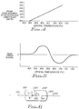
- Fig. 4 shows a graph of beam displacement versus crystal temperature. For small changes in temperature the relation is approximately linear. It has been found that a one degree Celsius change in temperature will result in the angle of the output beam 50 changing such that the corresponding beam displacement is approximately one beam diameter at detector 60.
- Fig. 5 shows a graph of the temperature error signal from amplifier 66 versus crystal temperature. Depending upon the beam displacement, a negative or positive temperature error signal is produced. The temperature error signal provides a zero point on which to lock. It should be noted that at temperatures well above and below the critical phase matching temperature, the temperature error signal will also be zero. This occurs when the temperature of the nonlinear crystal is so far from the critical phase matching temperature that no second harmonic light is produced and no light is detected at detector 60. The rough temperature error signal from amplifier 122 ensures that the system will operate in the critical temperature range where the temperature error signal from amplifier 66 exists.
- Fig. 6 shows an alternative embodiment of a resonator and designated by the general reference number 300.
- Resonator 300 may be substituted for resonator 20 of system 10.
- Resonator 300 has a pair of mirrors 302 and 304, which are of similar construction to mirrors 22 and 26, respectively, of resonator 20.
- Fundamental frequency light 310 enters resonator 300 and is reflected back and forth inside resonator 300 along a path 312.
- a nonlinear crystal 320 is positioned within resonator 300 with its noncritical phase matching axis (A axis for KNbO3 at 856 nm fundamental frequency wavelength) offset at a slight angle 322 to path 312.
- Angle 322 may be approximately 0.1 to 5 degrees in a preferred embodiment.
- the second harmonic light 330 exits resonator 300 at mirror 304.
- Resonator 300 is impedance matched and mode matched to the incoming light as described above.
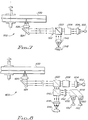
- Fig. 7 shows a phase change optical data storage system 500 which uses a laser system 502.
- Laser system 10 may be used for system 502.
- the light from system 502 is collimated by a lens 504 and passes to a circularizing optical element 506.
- Element 506 emits light having a circular cross-sectional beam pattern.
- Element 506 may be a prism.
- the light then passes through a polarizing beamsplitter 520 and a quarter waveplate 522.
- the light is reflected off of a mirror 524 and focussed by lens 526 onto an optical recording medium 530.
- Medium 530 may be a phase change type of optical recording medium.
- the light reflected from medium 530 returns through lens 526, is reflected off of mirror 524, passes through plate 522 to beamsplitter 520. Reflected light is then diverted by a beamsplitter 520 to an astigmatic lens 540. Lens 540 focuses the reflected light onto an optical detector 542. The recorded spots of the medium 530 have different reflectivities and these differences are detected by optical detector 542 as data ones and zero. Detector 542 also provides focus and tracking signals.
- Fig. 8 shows a magneto-optic data storage system 600 which uses a laser system 602.
- Laser system 10 may be used for system 602.
- the light from system 602 is collimated by a lens 604 and passes to circularizing optical element 606.
- Element 606 emits light having a circular cross-sectional beam pattern.
- Element 606 may be a prism.
- Beamsplitter 620 has reflectivities of RP > 0 and RS approximately equal to one (S and P represent the orthogonal polarization components of light).
- the light is then reflected off of a mirror 624 to a lens 626 and is focussed onto an optical recording medium 630.
- Medium 630 may be a magneto-optic type of optical recording medium.
- the light reflected from medium 630 returns through lens 626, reflects off of mirror 624, and enters beamsplitter 620.
- Beamsplitter 620 diverts the reflected light to an amplitude beamsplitter 640.
- Reflected data light is diverted to a half waveplate 642 and to a beamsplitter 644. Reflected light of other amplitudes passes straight through beamsplitter 640. This light is focussed by an astigmatic lens 646 to a quad detector 648 to produce tracking and focus signals.
- the medium 630 has recorded spots having either an up or down magnetic domain.
- the light reflected off of these spots has its plane of polarization rotated one way or the other depending upon the direction of the magnetic domain of the spot.
- Beamsplitter 644 separates the reflected light depending upon which way the plane of polarization has been rotated.
- the separated beams go to a lens 650 and an optical detector 652 or to a lens 660 and an optical detector 662.
- the difference in output signals of detectors 652 and 662 are the data ones and zeros.
Landscapes
- Physics & Mathematics (AREA)
- Nonlinear Science (AREA)
- General Physics & Mathematics (AREA)
- Optics & Photonics (AREA)
- Lasers (AREA)
Applications Claiming Priority (2)
| Application Number | Priority Date | Filing Date | Title |
|---|---|---|---|
| US07/669,157 US5093832A (en) | 1991-03-14 | 1991-03-14 | Laser system and method with temperature controlled crystal |
| US669157 | 1991-03-14 |
Publications (2)
| Publication Number | Publication Date |
|---|---|
| EP0503929A2 true EP0503929A2 (de) | 1992-09-16 |
| EP0503929A3 EP0503929A3 (en) | 1993-04-21 |
Family
ID=24685296
Family Applications (1)
| Application Number | Title | Priority Date | Filing Date |
|---|---|---|---|
| EP19920302095 Ceased EP0503929A3 (en) | 1991-03-14 | 1992-03-11 | Laser with temperature controlled harmonic generating crystal |
Country Status (3)
| Country | Link |
|---|---|
| US (1) | US5093832A (de) |
| EP (1) | EP0503929A3 (de) |
| JP (1) | JPH0760238B2 (de) |
Cited By (2)
| Publication number | Priority date | Publication date | Assignee | Title |
|---|---|---|---|---|
| WO2006041620A1 (en) * | 2004-10-05 | 2006-04-20 | Coherent, Inc. | Stabilized frequency-converted laser system |
| WO2016034416A1 (fr) * | 2014-09-05 | 2016-03-10 | Oxxius | Système de génération de faisceau laser par effet non linéaire à base de cavité microchip résonante |
Families Citing this family (37)
| Publication number | Priority date | Publication date | Assignee | Title |
|---|---|---|---|---|
| JP2689184B2 (ja) * | 1990-10-18 | 1997-12-10 | パイオニア株式会社 | 光波長変換装置 |
| JP2738785B2 (ja) * | 1991-06-27 | 1998-04-08 | 三菱電機株式会社 | 光磁気記録再生装置 |
| US5253259A (en) * | 1991-02-07 | 1993-10-12 | Matsushita Electric Industrial Co., Ltd. | Frequency doubler and visible laser source having a heater |
| US5353292A (en) * | 1991-10-31 | 1994-10-04 | Hoya Corporation | Laser light wavelength conversion apparatus capable of providing a uniform temperature distribution |
| US5351617A (en) * | 1992-07-20 | 1994-10-04 | Presstek, Inc. | Method for laser-discharge imaging a printing plate |
| US5339737B1 (en) * | 1992-07-20 | 1997-06-10 | Presstek Inc | Lithographic printing plates for use with laser-discharge imaging apparatus |
| US5379698A (en) * | 1992-07-20 | 1995-01-10 | Presstek, Inc. | Lithographic printing members for use with laser-discharge imaging |
| AU674518B2 (en) * | 1992-07-20 | 1997-01-02 | Presstek, Inc. | Lithographic printing plates for use with laser-discharge imaging apparatus |
| US5353705A (en) * | 1992-07-20 | 1994-10-11 | Presstek, Inc. | Lithographic printing members having secondary ablation layers for use with laser-discharge imaging apparatus |
| USRE35512F1 (en) * | 1992-07-20 | 1998-08-04 | Presstek Inc | Lithographic printing members for use with laser-discharge imaging |
| KR950002069B1 (ko) * | 1992-11-25 | 1995-03-10 | 삼성전자주식회사 | 제2고조파 발생장치(Second Harmonic Generator) |
| KR950002068B1 (ko) * | 1992-11-25 | 1995-03-10 | 삼성전자주식회사 | 제2고조파 발생방법 및 그 장치 |
| KR100252008B1 (ko) * | 1993-11-11 | 2000-05-01 | 윤종용 | 제2고조파 발생방법 및 장치 |
| KR100322691B1 (ko) * | 1995-01-27 | 2002-05-13 | 윤종용 | 제2고조파발생장치 |
| KR100363237B1 (ko) * | 1995-05-09 | 2003-02-05 | 삼성전자 주식회사 | 제2고조파 발생 방법 및 장치 |
| KR100363238B1 (ko) * | 1995-05-09 | 2003-02-05 | 삼성전자 주식회사 | 제2고조파 발생 방법 및 장치 |
| US5825793A (en) * | 1995-06-05 | 1998-10-20 | Hitachi Metals, Ltd. | Laser and laser applied units |
| WO1996040861A1 (en) * | 1995-06-07 | 1996-12-19 | Biolog, Inc. | Microbiological media for isolation and identification of enteric pathogens such as e. coli and salmonella |
| US5644422A (en) * | 1996-01-16 | 1997-07-01 | New Focus, Inc. | Techniques of radiation phase matching within optical crystals |
| US5974061A (en) * | 1997-12-19 | 1999-10-26 | Raytheon Company | Laser pump cavity apparatus with improved thermal lensing control, cooling, and fracture strength and method |
| US6002697A (en) * | 1998-04-03 | 1999-12-14 | Lambda Physik Gmbh | Diode pumped laser with frequency conversion into UV and DUV range |
| JP3508611B2 (ja) * | 1999-03-30 | 2004-03-22 | ウシオ電機株式会社 | 結晶保持装置 |
| US6614584B1 (en) | 2000-02-25 | 2003-09-02 | Lambda Physik Ag | Laser frequency converter with automatic phase matching adjustment |
| US6834066B2 (en) | 2000-04-18 | 2004-12-21 | Lambda Physik Ag | Stabilization technique for high repetition rate gas discharge lasers |
| US6862307B2 (en) * | 2000-05-15 | 2005-03-01 | Lambda Physik Ag | Electrical excitation circuit for a pulsed gas laser |
| US6389817B1 (en) * | 2000-06-26 | 2002-05-21 | International Business Machines Corporation | Internal temperature control for a microdrive |
| US6608852B2 (en) | 2000-08-25 | 2003-08-19 | Lameda Physik Ag | Gain module for diode-pumped solid state laser and amplifier |
| AU2002228819A1 (en) | 2000-11-22 | 2002-06-03 | Visx Incorporated | Temperature actuated positioning device for non-linear optical elements |
| US7218653B2 (en) * | 2003-11-27 | 2007-05-15 | Mitsubishi Materials Corporation | Wavelength conversion method and wavelength conversion element |
| FI118379B (fi) * | 2004-02-25 | 2007-10-31 | Stora Enso Oyj | Menetelmä paperin tai kartongin saumaamiseksi |
| KR100977048B1 (ko) * | 2006-06-12 | 2010-08-20 | 삼성전자주식회사 | 비선형 광변조기 |
| US8199396B2 (en) * | 2007-12-26 | 2012-06-12 | Panasonic Corporation | Laser light source, and image display apparatus and processing apparatus using the same |
| WO2017060967A1 (ja) * | 2015-10-06 | 2017-04-13 | 株式会社島津製作所 | 波長変換装置 |
| CN107317217B (zh) * | 2016-04-26 | 2019-12-17 | 中国科学院理化技术研究所 | 一种基于ⅱ类非临界相位匹配的共振增强腔倍频装置 |
| US11378863B1 (en) * | 2021-04-15 | 2022-07-05 | Coherent Kaiserslautern GmbH | Nonlinear frequency conversion with variable average power and stable heat load |
| KR102451406B1 (ko) * | 2022-04-11 | 2022-10-07 | 김영태 | 레이저 헤드 장치 및 그 사용 방법 |
| JP7132455B1 (ja) * | 2022-06-28 | 2022-09-06 | レーザーテック株式会社 | 光源装置、検査装置、および調整方法 |
Family Cites Families (3)
| Publication number | Priority date | Publication date | Assignee | Title |
|---|---|---|---|---|
| US3328723A (en) * | 1965-12-23 | 1967-06-27 | Bell Telephone Labor Inc | Optical frequency parametric oscillators and modulators with temperature and electrical control |
| US3588738A (en) * | 1968-09-03 | 1971-06-28 | Hughes Aircraft Co | Frequency stabilized laser |
| US3858056A (en) * | 1974-01-22 | 1974-12-31 | Westinghouse Electric Corp | Means and method for stabilized optimized temperature phase matched optical parametric generation |
-
1991
- 1991-03-14 US US07/669,157 patent/US5093832A/en not_active Expired - Fee Related
- 1991-12-04 JP JP3320271A patent/JPH0760238B2/ja not_active Expired - Fee Related
-
1992
- 1992-03-11 EP EP19920302095 patent/EP0503929A3/en not_active Ceased
Cited By (6)
| Publication number | Priority date | Publication date | Assignee | Title |
|---|---|---|---|---|
| WO2006041620A1 (en) * | 2004-10-05 | 2006-04-20 | Coherent, Inc. | Stabilized frequency-converted laser system |
| US7242700B2 (en) | 2004-10-05 | 2007-07-10 | Coherent, Inc. | Stabilized frequency-converted laser system |
| WO2016034416A1 (fr) * | 2014-09-05 | 2016-03-10 | Oxxius | Système de génération de faisceau laser par effet non linéaire à base de cavité microchip résonante |
| FR3025661A1 (fr) * | 2014-09-05 | 2016-03-11 | Oxxius | Systeme de generation de faisceau laser par effet non lineaire a base de cavite microchip resonante |
| US20170307956A1 (en) * | 2014-09-05 | 2017-10-26 | Oxxius | A resonant-microchip-cavity-based system for generating a laser beam via a nonlinear effect |
| US10108070B2 (en) * | 2014-09-05 | 2018-10-23 | Oxxius | Resonant-microchip-cavity-based system for generating a laser beam via a nonlinear effect |
Also Published As
| Publication number | Publication date |
|---|---|
| JPH0511300A (ja) | 1993-01-19 |
| US5093832A (en) | 1992-03-03 |
| EP0503929A3 (en) | 1993-04-21 |
| JPH0760238B2 (ja) | 1995-06-28 |
Similar Documents
| Publication | Publication Date | Title |
|---|---|---|
| US5093832A (en) | Laser system and method with temperature controlled crystal | |
| EP0486192B1 (de) | Halbleiterlasersystem mit nichtlinearem Kristallresonator | |
| US5377212A (en) | Solid-state laser device including uniaxial laser crystal emitting linearly polarized fundamental wave and nonlinear optical crystal emitting linearly polarized harmonic wave | |
| US5095491A (en) | Laser system and method | |
| CA2061331C (en) | Laser system and method | |
| AU659270B2 (en) | Laser light beam generating apparatus | |
| US5303250A (en) | Laser light generating apparatus | |
| US5111468A (en) | Diode laser frequency doubling using nonlinear crystal resonator with electronic resonance locking | |
| US6130901A (en) | SHG laser stabilizing control device and optical disk recording/reproduction device | |
| US5060233A (en) | Miniature blue-green laser source using second-harmonic generation | |
| KR100363237B1 (ko) | 제2고조파 발생 방법 및 장치 | |
| JP2007019361A (ja) | 周波数安定化レーザ | |
| US5394414A (en) | Laser system and method having a nonlinear crystal resonator | |
| US5068546A (en) | Solid state laser operating with frequency doubling and stabilized by an external resonator | |
| US5048047A (en) | Passive absorptive resonator laser system and method | |
| US5224193A (en) | First order mode frequency doubler system and method | |
| US5253313A (en) | Optical guide apparatus | |
| US5325348A (en) | Wavelength converting element and system for recording and reproducing optical information | |
| US6072762A (en) | Optical disk recording/reproducing method and apparatus for preventing wave length shift during recording and reproducing operations | |
| KR100363238B1 (ko) | 제2고조파 발생 방법 및 장치 | |
| US5084840A (en) | Passive absorptive rensonator laser system and method | |
| JP2963220B2 (ja) | 第2高調波発生装置及び光記録媒体のピックアップ | |
| EP0520813B1 (de) | Magnetooptisches Aufzeichnungs/Wiedergabegerät | |
| JPH04121835A (ja) | 光情報記録再生装置 | |
| JPH09116219A (ja) | レーザ光発生装置、およびレーザ応用装置 |
Legal Events
| Date | Code | Title | Description |
|---|---|---|---|
| PUAI | Public reference made under article 153(3) epc to a published international application that has entered the european phase |
Free format text: ORIGINAL CODE: 0009012 |
|
| AK | Designated contracting states |
Kind code of ref document: A2 Designated state(s): DE FR GB |
|
| PUAL | Search report despatched |
Free format text: ORIGINAL CODE: 0009013 |
|
| 17P | Request for examination filed |
Effective date: 19930120 |
|
| AK | Designated contracting states |
Kind code of ref document: A3 Designated state(s): DE FR GB |
|
| GRAG | Despatch of communication of intention to grant |
Free format text: ORIGINAL CODE: EPIDOS AGRA |
|
| 17Q | First examination report despatched |
Effective date: 19960202 |
|
| 18R | Application refused |
Effective date: 19960722 |