EP0504256B1 - Vibratory ion vapor generator - Google Patents
Vibratory ion vapor generator Download PDFInfo
- Publication number
- EP0504256B1 EP0504256B1 EP91901047A EP91901047A EP0504256B1 EP 0504256 B1 EP0504256 B1 EP 0504256B1 EP 91901047 A EP91901047 A EP 91901047A EP 91901047 A EP91901047 A EP 91901047A EP 0504256 B1 EP0504256 B1 EP 0504256B1
- Authority
- EP
- European Patent Office
- Prior art keywords
- ion
- container
- vapor
- generator according
- liquid surface
- Prior art date
- Legal status (The legal status is an assumption and is not a legal conclusion. Google has not performed a legal analysis and makes no representation as to the accuracy of the status listed.)
- Expired - Lifetime
Links
- 150000002500 ions Chemical class 0.000 claims abstract description 94
- 239000007788 liquid Substances 0.000 claims abstract description 38
- 238000002485 combustion reaction Methods 0.000 claims abstract description 27
- 239000003570 air Substances 0.000 claims description 33
- 238000013019 agitation Methods 0.000 claims description 15
- 238000000034 method Methods 0.000 claims description 7
- 239000012080 ambient air Substances 0.000 claims description 5
- 238000004519 manufacturing process Methods 0.000 claims description 3
- 230000003134 recirculating effect Effects 0.000 claims description 3
- 230000005611 electricity Effects 0.000 claims 2
- 230000009977 dual effect Effects 0.000 claims 1
- 230000002708 enhancing effect Effects 0.000 claims 1
- 230000001939 inductive effect Effects 0.000 claims 1
- 238000005086 pumping Methods 0.000 claims 1
- 235000019645 odor Nutrition 0.000 abstract description 6
- 239000000446 fuel Substances 0.000 abstract description 5
- 238000010438 heat treatment Methods 0.000 abstract description 5
- 230000029058 respiratory gaseous exchange Effects 0.000 abstract description 4
- 239000002085 irritant Substances 0.000 abstract description 3
- 231100000021 irritant Toxicity 0.000 abstract description 3
- 230000001473 noxious effect Effects 0.000 abstract description 2
- 238000006555 catalytic reaction Methods 0.000 abstract 1
- XLYOFNOQVPJJNP-UHFFFAOYSA-N water Chemical compound O XLYOFNOQVPJJNP-UHFFFAOYSA-N 0.000 description 7
- 239000007789 gas Substances 0.000 description 6
- 238000012360 testing method Methods 0.000 description 6
- 230000005587 bubbling Effects 0.000 description 5
- 239000003502 gasoline Substances 0.000 description 5
- ATUOYWHBWRKTHZ-UHFFFAOYSA-N Propane Chemical compound CCC ATUOYWHBWRKTHZ-UHFFFAOYSA-N 0.000 description 4
- 230000008901 benefit Effects 0.000 description 4
- 238000009434 installation Methods 0.000 description 4
- 230000009467 reduction Effects 0.000 description 3
- WWYNJERNGUHSAO-XUDSTZEESA-N (+)-Norgestrel Chemical compound O=C1CC[C@@H]2[C@H]3CC[C@](CC)([C@](CC4)(O)C#C)[C@@H]4[C@@H]3CCC2=C1 WWYNJERNGUHSAO-XUDSTZEESA-N 0.000 description 2
- 239000001273 butane Substances 0.000 description 2
- 239000003245 coal Substances 0.000 description 2
- 239000000356 contaminant Substances 0.000 description 2
- 239000002283 diesel fuel Substances 0.000 description 2
- 230000000694 effects Effects 0.000 description 2
- 238000005516 engineering process Methods 0.000 description 2
- 230000036541 health Effects 0.000 description 2
- 208000015181 infectious disease Diseases 0.000 description 2
- 239000003949 liquefied natural gas Substances 0.000 description 2
- IJDNQMDRQITEOD-UHFFFAOYSA-N n-butane Chemical compound CCCC IJDNQMDRQITEOD-UHFFFAOYSA-N 0.000 description 2
- OFBQJSOFQDEBGM-UHFFFAOYSA-N n-pentane Natural products CCCCC OFBQJSOFQDEBGM-UHFFFAOYSA-N 0.000 description 2
- 230000008569 process Effects 0.000 description 2
- 239000001294 propane Substances 0.000 description 2
- 239000002023 wood Substances 0.000 description 2
- 241000894006 Bacteria Species 0.000 description 1
- 239000004215 Carbon black (E152) Substances 0.000 description 1
- 241000287828 Gallus gallus Species 0.000 description 1
- 230000003416 augmentation Effects 0.000 description 1
- 230000009286 beneficial effect Effects 0.000 description 1
- 230000003197 catalytic effect Effects 0.000 description 1
- 235000019504 cigarettes Nutrition 0.000 description 1
- 239000012153 distilled water Substances 0.000 description 1
- 230000008030 elimination Effects 0.000 description 1
- 238000003379 elimination reaction Methods 0.000 description 1
- 229930195733 hydrocarbon Natural products 0.000 description 1
- 150000002430 hydrocarbons Chemical class 0.000 description 1
- 230000002458 infectious effect Effects 0.000 description 1
- 230000007246 mechanism Effects 0.000 description 1
- 239000003921 oil Substances 0.000 description 1
- 230000000979 retarding effect Effects 0.000 description 1
- 239000000779 smoke Substances 0.000 description 1
Images


Classifications
-
- B—PERFORMING OPERATIONS; TRANSPORTING
- B05—SPRAYING OR ATOMISING IN GENERAL; APPLYING FLUENT MATERIALS TO SURFACES, IN GENERAL
- B05B—SPRAYING APPARATUS; ATOMISING APPARATUS; NOZZLES
- B05B17/00—Apparatus for spraying or atomising liquids or other fluent materials, not covered by the preceding groups
- B05B17/04—Apparatus for spraying or atomising liquids or other fluent materials, not covered by the preceding groups operating with special methods
- B05B17/06—Apparatus for spraying or atomising liquids or other fluent materials, not covered by the preceding groups operating with special methods using ultrasonic or other kinds of vibrations
- B05B17/0607—Apparatus for spraying or atomising liquids or other fluent materials, not covered by the preceding groups operating with special methods using ultrasonic or other kinds of vibrations generated by electrical means, e.g. piezoelectric transducers
- B05B17/0615—Apparatus for spraying or atomising liquids or other fluent materials, not covered by the preceding groups operating with special methods using ultrasonic or other kinds of vibrations generated by electrical means, e.g. piezoelectric transducers spray being produced at the free surface of the liquid or other fluent material in a container and subjected to the vibrations
-
- F—MECHANICAL ENGINEERING; LIGHTING; HEATING; WEAPONS; BLASTING
- F02—COMBUSTION ENGINES; HOT-GAS OR COMBUSTION-PRODUCT ENGINE PLANTS
- F02M—SUPPLYING COMBUSTION ENGINES IN GENERAL WITH COMBUSTIBLE MIXTURES OR CONSTITUENTS THEREOF
- F02M25/00—Engine-pertinent apparatus for adding non-fuel substances or small quantities of secondary fuel to combustion-air, main fuel or fuel-air mixture
- F02M25/022—Adding fuel and water emulsion, water or steam
- F02M25/0221—Details of the water supply system, e.g. pumps or arrangement of valves
- F02M25/0224—Water treatment or cleaning
-
- F—MECHANICAL ENGINEERING; LIGHTING; HEATING; WEAPONS; BLASTING
- F02—COMBUSTION ENGINES; HOT-GAS OR COMBUSTION-PRODUCT ENGINE PLANTS
- F02M—SUPPLYING COMBUSTION ENGINES IN GENERAL WITH COMBUSTIBLE MIXTURES OR CONSTITUENTS THEREOF
- F02M25/00—Engine-pertinent apparatus for adding non-fuel substances or small quantities of secondary fuel to combustion-air, main fuel or fuel-air mixture
- F02M25/022—Adding fuel and water emulsion, water or steam
- F02M25/025—Adding water
- F02M25/028—Adding water into the charge intakes
-
- F—MECHANICAL ENGINEERING; LIGHTING; HEATING; WEAPONS; BLASTING
- F02—COMBUSTION ENGINES; HOT-GAS OR COMBUSTION-PRODUCT ENGINE PLANTS
- F02B—INTERNAL-COMBUSTION PISTON ENGINES; COMBUSTION ENGINES IN GENERAL
- F02B1/00—Engines characterised by fuel-air mixture compression
- F02B1/02—Engines characterised by fuel-air mixture compression with positive ignition
- F02B1/04—Engines characterised by fuel-air mixture compression with positive ignition with fuel-air mixture admission into cylinder
-
- Y—GENERAL TAGGING OF NEW TECHNOLOGICAL DEVELOPMENTS; GENERAL TAGGING OF CROSS-SECTIONAL TECHNOLOGIES SPANNING OVER SEVERAL SECTIONS OF THE IPC; TECHNICAL SUBJECTS COVERED BY FORMER USPC CROSS-REFERENCE ART COLLECTIONS [XRACs] AND DIGESTS
- Y02—TECHNOLOGIES OR APPLICATIONS FOR MITIGATION OR ADAPTATION AGAINST CLIMATE CHANGE
- Y02T—CLIMATE CHANGE MITIGATION TECHNOLOGIES RELATED TO TRANSPORTATION
- Y02T10/00—Road transport of goods or passengers
- Y02T10/10—Internal combustion engine [ICE] based vehicles
- Y02T10/12—Improving ICE efficiencies
Definitions
- the present invention relates to ion vapor generation and to improved devices for generating ion vapors.
- the invention has particular utility in combustion enhancement of furnaces using oil, gas, coal, wood and the like fuels, and to combustion enhancement of internal combustion engines using gasoline, diesel oil and/or LNG, propane or butane gas and the like fuels, and will be described in connection with such utility, although other utilities including, for example, the field of health for control of infectious airborne contaminants, irritants to breathing and odors in the air are contemplated.
- the present invention provides an Ion-enriched Vapor generator comprising,
- the invention also provides a method for producing an ion enriched vapor, said method comprising :
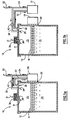
- FIG. 1a details a preferred embodiment of Vibratory Ion Vapor Generator 10 made in accordance with the present invention. It consists of a liquid container 12 partially filled with a liquid 14 containing H 2 O. The head space volume 15 above the liquid surface 16 is where the primary negative ion vapor accumulates after liberation from the liquid.
- a combination vibrator and air pump 18 is mechanically coupled 20 to the side wall of the liquid container 12. The liquid surface 16 is caused to be agitated with a resulting rippling effect as caused by the vibrator unit 18 when operating.
- the vibratory levels, frequency and amplitude, must be adjusted so as substantially to maintain continuous surface tension on the liquid surface. This agitation causes negative ions to be released from the liquid 14 and out through the liquid surface 16.
- Elevated levels of surface agitation that lead to substantial disruption of the surface tension will (1) significantly limit the effective generation of negative ions and/or (2) cause undesired levels of positive ions to be generated in place of negative ions, defeating the purpose of the negative ion generator.
- the air pump portion of the vibrator unit 18 recirculates the ion vapor in the volume 15 by drawing the vapor 30 into the pump inlet 22 and returning it to the volume 15 via the pump outlet 24 and the vapor return 26 to the exit 28.
- a portion of the ion vapor flow exiting the pump 18 via the air pump outlet 24 is caused to flow out through conduit 27, the ion vapor 32 being directed to the combustion process or other process.
- the portion of the ion vapor in 24 caused to divide and flow through 26 and 27 is controlled by the adjustment of vapor flow valve 42.
- the valve 42 can be replaced with a fixed restrictive orifice means where adjustment is not required.
- Ambient air 31 is drawn in through filter 36 and into the volume 15 to replace that directed to a combustion process or other application 32.
- a one-way flow control valve 38 to prevent backflow is optional and may be desirable in some applications.
- FIG. 1b A variation of the ion vapor generator 10 made in accordance with the present invention is shown in Figure 1b.
- the vibration means 19 used to agitate the liquid surface 16 is separate from the air pump device 21.
- the vibrator 19 is mechanically coupled 20 to the liquid container 12, while the air pump 21 is located and powered separately.
- An alternative arrangement is to introduce the vibratory means 19 directly into and submerged in the liquid 14 within the container 12, or applying any other functionally equivalent means for vibratory agitation of the liquid surface 16.
- FIG. 1c A third embodiment of Vibratory Ion Vapor Generator 10 is shown in Figure 1c.
- Ambient air 31 is drawn into the air pump 21 air inlet 22 and introduced to the generator 10 at point 33, via an air pump outlet 24.
- the ion vapor 32 is removed from the generator 10 at point 34.
- FIG. 1d A fourth embodiment of Vibratory Ion Vapor Generator 10 is shown in Figure 1d.
- Ambient air 31 is drawn into the generator 10 at point 33.
- Ion vapor 32 is drawn out of the generator 10 at point 34 by air pump 21 at air pump inlet 22, and directed at the air pump outlet 24 to the point of application.
- the negative ion outflow 32 is directed through ion vapor feed 31 to the area requiring ion treatment.
- a negative ion vapor generator 10 supplies a source of ions 32 which are transported via a feed line 54 to the oil burner and combustion region 52 of the furnace 50.
- Similar furnaces fueled with gas, coal, wood or the like are connected to the ion vapor generator 10 by an ion vapor feed line 54.
- a negative ion vapor generator 10 supplies a source of ion vapor 32 via a feed line 64 to the gas burner combustion region 62.
- the application of the negative ion vapor generator of the present invention 10 to an internal combustion engine 70 is illustrated in Figure 4.
- the ion vapor 32 is feed to the engine via the ion vapor feed line 72.
- the ion vapor 32 is directed into the engine air intake 74 and enters the engine combustion area along with the normal intake air.
- the engine may be the type fueled with gasoline, diesel oil, LNG, propane, butane or the like fuels.
- the invention ion generator 10 may require an initial bypass valve 42 adjustment when installed with differently fueled engines or heating furnaces. Once installed, further adjustment will not be required unless the combustion process or other application is significantly altered.
- the capacity requirements for optimum performance of the negative ion vapor generator 10 is determined by the general combustion process or other requirements of the application to which it is applied.
- Vibratory Ion Generators were assembled in accordance with Fig. 1A.
- the container comprised a one gallon plastic jar which was half filled with distilled water.
- An air pump (Model Hartz 83833, 110 VAC available from Hartz Mountain Corporation, Harrison, NJ) was used to circulate overheads in the container and to impart vibratory energy to the wall of the container which in turn caused vibrations in the water.
- the air pump operated at frequency of 60Hz and an amplitude of approximately 0,0762-0,1524 cm (0.03-0.06 inches). Ion laden overhead vapors where withdrawn from the container at a rate of 3,500 cc. per minute.
- the resulting Vibratory Ion Vapor Generator was evaluated and its performance confirmed for room odor control in six (6) separate test sites. The performance exceeded that achieved with the inventor's previous bubble ion generators for reduction and elimination of noxious odors and cigarette smoke.
- the first automobile was a 1984 Ford with a V6 3.8L gasoline engine.
- the ion vapor generator had a 0,946 liter (one (1) quart liquid) volume. It was filled halfway with distilled H 2 O.
- the vibrator and air pump were a combined unit, with a vibration frequency of approximately 60Hz.
- Bench testing of the ion vapor generator prior to installation on the automobile showed a ion electrical current of 10 -12 to 10 -11 mA. using a Keithley Model 610C electrometer. The unit was installed with the ion vapor being fed directly into the air intake filter assembly. Results of this test revealed an increase in gasoline kilometers per liter of from 8,93 to 10,20 (miles per gallon of from 21 to 24), or about a 15% increase.
- the present invention a Vibratory Ion Vapor Generator
- the ion flow which represents an electrical current had increased by 2 or 3 orders of magnitude over the prior bubble units, which operated at approximately 10 -14 mA.
- the present invention eliminates the need for adjustable flow control valves in the vapor lines as was typically required with prior bubble units.
- a one-way flow control valve to prevent an overpressure surge from a combustion region from entering the ion generator can be utilized.
- the vibratory units are self adjusting and do not require special calibration.
- the performance of vibrating ion vapor generators made in accordance with the present invention equals or exceeds that of the prior bubble units, in addition to the other operational and manufacturing benefits noted for the present invention.
Landscapes
- Engineering & Computer Science (AREA)
- Chemical & Material Sciences (AREA)
- Combustion & Propulsion (AREA)
- Mechanical Engineering (AREA)
- General Engineering & Computer Science (AREA)
- Water Supply & Treatment (AREA)
- Health & Medical Sciences (AREA)
- Public Health (AREA)
- Physical Or Chemical Processes And Apparatus (AREA)
- Air Supply (AREA)
- Treating Waste Gases (AREA)
- Special Spraying Apparatus (AREA)
- Oxygen, Ozone, And Oxides In General (AREA)
- Drying Of Solid Materials (AREA)
- Analysing Materials By The Use Of Radiation (AREA)
- Incineration Of Waste (AREA)
- Exhaust Gas After Treatment (AREA)
- Diaphragms For Electromechanical Transducers (AREA)
Applications Claiming Priority (3)
| Application Number | Priority Date | Filing Date | Title |
|---|---|---|---|
| US445457 | 1989-12-04 | ||
| US07/445,457 US4952340A (en) | 1989-12-04 | 1989-12-04 | Vibratory ion vapor generator and method |
| PCT/US1990/007048 WO1991008044A1 (en) | 1989-12-04 | 1990-12-03 | Vibratory ion vapor generator |
Publications (3)
| Publication Number | Publication Date |
|---|---|
| EP0504256A1 EP0504256A1 (en) | 1992-09-23 |
| EP0504256A4 EP0504256A4 (en) | 1992-10-28 |
| EP0504256B1 true EP0504256B1 (en) | 1998-06-10 |
Family
ID=23768977
Family Applications (1)
| Application Number | Title | Priority Date | Filing Date |
|---|---|---|---|
| EP91901047A Expired - Lifetime EP0504256B1 (en) | 1989-12-04 | 1990-12-03 | Vibratory ion vapor generator |
Country Status (9)
| Country | Link |
|---|---|
| US (1) | US4952340A (da) |
| EP (1) | EP0504256B1 (da) |
| JP (1) | JP2551889B2 (da) |
| AT (1) | ATE167089T1 (da) |
| CA (1) | CA2072140C (da) |
| DE (2) | DE504256T1 (da) |
| DK (1) | DK0504256T3 (da) |
| ES (1) | ES2034942T3 (da) |
| WO (1) | WO1991008044A1 (da) |
Families Citing this family (6)
| Publication number | Priority date | Publication date | Assignee | Title |
|---|---|---|---|---|
| GB8915978D0 (en) * | 1989-07-12 | 1989-08-31 | Mcdermott Matthew | Apparatus for dissolving solids in liquids |
| US5246632A (en) * | 1992-05-21 | 1993-09-21 | Wentworth Fred Albert Jr | Circulatory ion vapor generator and method |
| US5211890A (en) * | 1992-07-24 | 1993-05-18 | Wentworth Fred Albert Jr | Circulatory ion vapor generator and method |
| EP0678663A1 (en) * | 1994-01-06 | 1995-10-25 | IONIC FUEL TECHNOLOGY Ltd. | Ion vapour generating apparatus and method |
| EP0869317A1 (en) * | 1997-04-01 | 1998-10-07 | Ionic Fuel Technology, Inc. | Apparatus and method for improving performance of gas burner reactors |
| WO1998044254A2 (en) * | 1997-04-01 | 1998-10-08 | Ionic Fuel Technology, Inc. | Apparatus and method for improving performance of gas burner reactors |
Family Cites Families (9)
| Publication number | Priority date | Publication date | Assignee | Title |
|---|---|---|---|---|
| US2420691A (en) * | 1945-05-05 | 1947-05-20 | Vang Alfred | Evaporator |
| AR208304A1 (es) * | 1974-01-02 | 1976-12-20 | Wentworth F | Un metodo para agregar vapor de agua a la mezcla combustible en un aparato de combustion que tiene una admision forzada de aire y un aparato para ilevar a cabo el metodo |
| US4016837A (en) * | 1974-01-02 | 1977-04-12 | Wentworth Fred Albert Jr | Vapor intake system for internal combustion engines |
| USD253907S (en) | 1977-07-21 | 1980-01-08 | Wentworth Jr Fred A | Vaporizer for a combustion system |
| US4257989A (en) * | 1979-02-22 | 1981-03-24 | Tdk Electronics Co., Ltd. | Humidifier |
| US4410467A (en) * | 1981-11-09 | 1983-10-18 | Wentworth Fred Albert Jr | Ion-vapor generator and method |
| US4612777A (en) * | 1983-07-08 | 1986-09-23 | Sanyo Electric Co., Ltd. | Humidifier unit for refrigerated display cabinets |
| DE3425549A1 (de) * | 1984-07-11 | 1986-01-16 | Siemens AG, 1000 Berlin und 8000 München | Verfahren und vorrichtung zur verbesserung der probenaerosolausbeute in der plasmaangeregten, sequentiellen optischen spektralanalyse |
| IL80635A0 (en) * | 1986-11-14 | 1987-02-27 | Rhinotherm Netzer Sereni | Liquid atomizer particularly useful for therapeutic purposes |
-
1989
- 1989-12-04 US US07/445,457 patent/US4952340A/en not_active Expired - Lifetime
-
1990
- 1990-12-03 AT AT91901047T patent/ATE167089T1/de not_active IP Right Cessation
- 1990-12-03 WO PCT/US1990/007048 patent/WO1991008044A1/en not_active Ceased
- 1990-12-03 ES ES91901047T patent/ES2034942T3/es not_active Expired - Lifetime
- 1990-12-03 EP EP91901047A patent/EP0504256B1/en not_active Expired - Lifetime
- 1990-12-03 DE DE199191901047T patent/DE504256T1/de active Pending
- 1990-12-03 DE DE69032411T patent/DE69032411T2/de not_active Expired - Fee Related
- 1990-12-03 JP JP3501578A patent/JP2551889B2/ja not_active Expired - Fee Related
- 1990-12-03 DK DK91901047T patent/DK0504256T3/da active
- 1990-12-03 CA CA002072140A patent/CA2072140C/en not_active Expired - Fee Related
Also Published As
| Publication number | Publication date |
|---|---|
| CA2072140C (en) | 1994-05-31 |
| EP0504256A1 (en) | 1992-09-23 |
| US4952340A (en) | 1990-08-28 |
| ATE167089T1 (de) | 1998-06-15 |
| ES2034942T3 (es) | 1998-08-16 |
| JP2551889B2 (ja) | 1996-11-06 |
| DE69032411T2 (de) | 1999-01-07 |
| CA2072140A1 (en) | 1991-06-05 |
| EP0504256A4 (en) | 1992-10-28 |
| DE504256T1 (de) | 1993-05-19 |
| WO1991008044A1 (en) | 1991-06-13 |
| DK0504256T3 (da) | 1999-03-22 |
| DE69032411D1 (de) | 1998-07-16 |
| ES2034942T1 (es) | 1993-04-16 |
| JPH04507061A (ja) | 1992-12-10 |
Similar Documents
| Publication | Publication Date | Title |
|---|---|---|
| US4368711A (en) | Apparatus and a method for operating an internal combustion engine | |
| EP0372353B1 (en) | Fuel for reducing the noxiousness of exhaust gases, particularly for internal-combustion engines | |
| KR100374967B1 (ko) | 증기를내연기관의흡기에공급하는방법및그방법을실시하는장치 | |
| EP0504256B1 (en) | Vibratory ion vapor generator | |
| US4632067A (en) | Vapor injection device | |
| JPWO1998042807A1 (ja) | 低公害燃料の製造方法及びその製造装置 | |
| GR3035950T3 (en) | Apparatus for combustion enhancing and method | |
| CN1168166A (zh) | 用沼气驱动的发电机设备 | |
| US5211890A (en) | Circulatory ion vapor generator and method | |
| JPH029936A (ja) | 織機のマーキング装置 | |
| CN1042570C (zh) | 含水燃料的供给方法 | |
| US5246632A (en) | Circulatory ion vapor generator and method | |
| WO2002042629A1 (en) | Method and apparatus for adding ozone to the intake air and fuel system of an internal combustion engine for vehicles | |
| RU2059096C1 (ru) | Способ мамаева питания двигателя внутреннего сгорания и устройство для его осуществления | |
| SU1240943A1 (ru) | Способ питани двигател внутреннего сгорани | |
| AU2730795A (en) | Process for improving fuel spraying in internal combustion engines | |
| SU756060A1 (ru) | Способ приготовления топливоводянои смеси для питания двигателя внутреннего сгорания 1 | |
| EP0678663A1 (en) | Ion vapour generating apparatus and method | |
| RU2708180C1 (ru) | Двс с магнитно-каталитической камерой сгорания и с ультразвуковым парогенератором и способ подачи газо-водовоздушной топливной смеси в камеру сгорания этого двс | |
| JPH05256218A (ja) | 熱機関の吸気装置 | |
| AU727128C (en) | Apparatus for combustion enhancing and method | |
| KR970027776A (ko) | 차량의 가솔린/가스연료 가변공급장치 | |
| DE2108500A1 (de) | Ozonisierter Treibstoff fur Verbrennungsmotoren (genannt Ozon vergaser) | |
| FR2284046A1 (fr) | Dispositif pour ameliorer la combustion d'un carburant dans l'air | |
| RU94028173A (ru) | Устройство для регулирования уровня топлива в поплавковой камере карбюратора |
Legal Events
| Date | Code | Title | Description |
|---|---|---|---|
| PUAI | Public reference made under article 153(3) epc to a published international application that has entered the european phase |
Free format text: ORIGINAL CODE: 0009012 |
|
| 17P | Request for examination filed |
Effective date: 19920521 |
|
| AK | Designated contracting states |
Kind code of ref document: A1 Designated state(s): AT BE CH DE DK ES FR GB IT LI NL SE |
|
| A4 | Supplementary search report drawn up and despatched |
Effective date: 19920904 |
|
| AK | Designated contracting states |
Kind code of ref document: A4 Designated state(s): AT BE CH DE DK ES FR GB IT LI NL SE |
|
| ITCL | It: translation for ep claims filed |
Representative=s name: JACOBACCI CASETTA & PERANI S.P.A. |
|
| TCNL | Nl: translation of patent claims filed | ||
| EL | Fr: translation of claims filed | ||
| TCAT | At: translation of patent claims filed | ||
| REG | Reference to a national code |
Ref country code: ES Ref legal event code: BA2A Ref document number: 2034942 Country of ref document: ES Kind code of ref document: T1 |
|
| DET | De: translation of patent claims | ||
| 17Q | First examination report despatched |
Effective date: 19940103 |
|
| GRAG | Despatch of communication of intention to grant |
Free format text: ORIGINAL CODE: EPIDOS AGRA |
|
| GRAG | Despatch of communication of intention to grant |
Free format text: ORIGINAL CODE: EPIDOS AGRA |
|
| GRAH | Despatch of communication of intention to grant a patent |
Free format text: ORIGINAL CODE: EPIDOS IGRA |
|
| GRAH | Despatch of communication of intention to grant a patent |
Free format text: ORIGINAL CODE: EPIDOS IGRA |
|
| DIN1 | Information on inventor provided before grant (deleted) | ||
| RAP1 | Party data changed (applicant data changed or rights of an application transferred) |
Owner name: IONIC FUEL TECHNOLOGY, INC. |
|
| GRAA | (expected) grant |
Free format text: ORIGINAL CODE: 0009210 |
|
| RIN1 | Information on inventor provided before grant (corrected) |
Inventor name: WENTWORTH FRED, A., FR. |
|
| AK | Designated contracting states |
Kind code of ref document: B1 Designated state(s): AT BE CH DE DK ES FR GB IT LI NL SE |
|
| REF | Corresponds to: |
Ref document number: 167089 Country of ref document: AT Date of ref document: 19980615 Kind code of ref document: T |
|
| REG | Reference to a national code |
Ref country code: CH Ref legal event code: NV Representative=s name: BOVARD AG PATENTANWAELTE Ref country code: CH Ref legal event code: EP |
|
| REF | Corresponds to: |
Ref document number: 69032411 Country of ref document: DE Date of ref document: 19980716 |
|
| ITF | It: translation for a ep patent filed | ||
| REG | Reference to a national code |
Ref country code: ES Ref legal event code: FG2A Ref document number: 2034942 Country of ref document: ES Kind code of ref document: T3 |
|
| ET | Fr: translation filed | ||
| PGFP | Annual fee paid to national office [announced via postgrant information from national office to epo] |
Ref country code: SE Payment date: 19981119 Year of fee payment: 9 |
|
| PGFP | Annual fee paid to national office [announced via postgrant information from national office to epo] |
Ref country code: DK Payment date: 19981120 Year of fee payment: 9 |
|
| PGFP | Annual fee paid to national office [announced via postgrant information from national office to epo] |
Ref country code: AT Payment date: 19981123 Year of fee payment: 9 |
|
| PGFP | Annual fee paid to national office [announced via postgrant information from national office to epo] |
Ref country code: CH Payment date: 19981127 Year of fee payment: 9 |
|
| PGFP | Annual fee paid to national office [announced via postgrant information from national office to epo] |
Ref country code: ES Payment date: 19981216 Year of fee payment: 9 |
|
| REG | Reference to a national code |
Ref country code: DK Ref legal event code: T3 |
|
| PLBE | No opposition filed within time limit |
Free format text: ORIGINAL CODE: 0009261 |
|
| STAA | Information on the status of an ep patent application or granted ep patent |
Free format text: STATUS: NO OPPOSITION FILED WITHIN TIME LIMIT |
|
| 26N | No opposition filed | ||
| PG25 | Lapsed in a contracting state [announced via postgrant information from national office to epo] |
Ref country code: DK Free format text: LAPSE BECAUSE OF NON-PAYMENT OF DUE FEES Effective date: 19991203 Ref country code: AT Free format text: LAPSE BECAUSE OF NON-PAYMENT OF DUE FEES Effective date: 19991203 |
|
| PG25 | Lapsed in a contracting state [announced via postgrant information from national office to epo] |
Ref country code: SE Free format text: LAPSE BECAUSE OF NON-PAYMENT OF DUE FEES Effective date: 19991204 |
|
| PG25 | Lapsed in a contracting state [announced via postgrant information from national office to epo] |
Ref country code: LI Free format text: LAPSE BECAUSE OF NON-PAYMENT OF DUE FEES Effective date: 19991231 Ref country code: CH Free format text: LAPSE BECAUSE OF NON-PAYMENT OF DUE FEES Effective date: 19991231 |
|
| EUG | Se: european patent has lapsed |
Ref document number: 91901047.0 |
|
| REG | Reference to a national code |
Ref country code: DK Ref legal event code: EBP |
|
| PG25 | Lapsed in a contracting state [announced via postgrant information from national office to epo] |
Ref country code: ES Free format text: LAPSE BECAUSE OF NON-PAYMENT OF DUE FEES Effective date: 20001204 |
|
| REG | Reference to a national code |
Ref country code: GB Ref legal event code: IF02 |
|
| PGFP | Annual fee paid to national office [announced via postgrant information from national office to epo] |
Ref country code: NL Payment date: 20031216 Year of fee payment: 14 |
|
| PGFP | Annual fee paid to national office [announced via postgrant information from national office to epo] |
Ref country code: FR Payment date: 20031218 Year of fee payment: 14 |
|
| PGFP | Annual fee paid to national office [announced via postgrant information from national office to epo] |
Ref country code: GB Payment date: 20031224 Year of fee payment: 14 |
|
| PGFP | Annual fee paid to national office [announced via postgrant information from national office to epo] |
Ref country code: BE Payment date: 20040128 Year of fee payment: 14 |
|
| PGFP | Annual fee paid to national office [announced via postgrant information from national office to epo] |
Ref country code: DE Payment date: 20040202 Year of fee payment: 14 |
|
| REG | Reference to a national code |
Ref country code: ES Ref legal event code: FD2A Effective date: 20010113 |
|
| PG25 | Lapsed in a contracting state [announced via postgrant information from national office to epo] |
Ref country code: GB Free format text: LAPSE BECAUSE OF NON-PAYMENT OF DUE FEES Effective date: 20041203 |
|
| PG25 | Lapsed in a contracting state [announced via postgrant information from national office to epo] |
Ref country code: BE Free format text: LAPSE BECAUSE OF NON-PAYMENT OF DUE FEES Effective date: 20041231 |
|
| BERE | Be: lapsed |
Owner name: *IONIC FUEL TECHNOLOGY INC. Effective date: 20041231 |
|
| PG25 | Lapsed in a contracting state [announced via postgrant information from national office to epo] |
Ref country code: NL Free format text: LAPSE BECAUSE OF NON-PAYMENT OF DUE FEES Effective date: 20050701 Ref country code: DE Free format text: LAPSE BECAUSE OF NON-PAYMENT OF DUE FEES Effective date: 20050701 |
|
| GBPC | Gb: european patent ceased through non-payment of renewal fee |
Effective date: 20041203 |
|
| PG25 | Lapsed in a contracting state [announced via postgrant information from national office to epo] |
Ref country code: FR Free format text: LAPSE BECAUSE OF NON-PAYMENT OF DUE FEES Effective date: 20050831 |
|
| NLV4 | Nl: lapsed or anulled due to non-payment of the annual fee |
Effective date: 20050701 |
|
| REG | Reference to a national code |
Ref country code: FR Ref legal event code: ST |
|
| PG25 | Lapsed in a contracting state [announced via postgrant information from national office to epo] |
Ref country code: IT Free format text: LAPSE BECAUSE OF NON-PAYMENT OF DUE FEES Effective date: 20051203 |
|
| BERE | Be: lapsed |
Owner name: *IONIC FUEL TECHNOLOGY INC. Effective date: 20041231 |