EP0504352B1 - Procede et dispositif pour la fabrication de cylindres de texturisation - Google Patents
Procede et dispositif pour la fabrication de cylindres de texturisation Download PDFInfo
- Publication number
- EP0504352B1 EP0504352B1 EP91917190A EP91917190A EP0504352B1 EP 0504352 B1 EP0504352 B1 EP 0504352B1 EP 91917190 A EP91917190 A EP 91917190A EP 91917190 A EP91917190 A EP 91917190A EP 0504352 B1 EP0504352 B1 EP 0504352B1
- Authority
- EP
- European Patent Office
- Prior art keywords
- electron beam
- during
- intervals
- working
- texture
- Prior art date
- Legal status (The legal status is an assumption and is not a legal conclusion. Google has not performed a legal analysis and makes no representation as to the accuracy of the status listed.)
- Expired - Lifetime
Links
- 238000000034 method Methods 0.000 title claims abstract description 28
- 238000004519 manufacturing process Methods 0.000 title claims abstract description 7
- 230000008569 process Effects 0.000 title abstract description 6
- 238000010894 electron beam technology Methods 0.000 claims abstract description 42
- 238000002203 pretreatment Methods 0.000 claims description 6
- 230000003068 static effect Effects 0.000 claims description 5
- 238000002844 melting Methods 0.000 claims description 2
- 230000008018 melting Effects 0.000 claims description 2
- 238000004140 cleaning Methods 0.000 claims 1
- 238000004381 surface treatment Methods 0.000 abstract 1
- 230000005855 radiation Effects 0.000 description 8
- 229910000831 Steel Inorganic materials 0.000 description 6
- 238000010586 diagram Methods 0.000 description 6
- 239000010959 steel Substances 0.000 description 6
- 230000008901 benefit Effects 0.000 description 5
- 238000011156 evaluation Methods 0.000 description 5
- 239000000463 material Substances 0.000 description 5
- 230000015572 biosynthetic process Effects 0.000 description 4
- 229910052751 metal Inorganic materials 0.000 description 4
- 239000002184 metal Substances 0.000 description 4
- 150000002500 ions Chemical class 0.000 description 3
- 230000009471 action Effects 0.000 description 2
- QVGXLLKOCUKJST-UHFFFAOYSA-N atomic oxygen Chemical compound [O] QVGXLLKOCUKJST-UHFFFAOYSA-N 0.000 description 2
- 238000005452 bending Methods 0.000 description 2
- 230000008859 change Effects 0.000 description 2
- 230000001934 delay Effects 0.000 description 2
- 238000013461 design Methods 0.000 description 2
- 238000001514 detection method Methods 0.000 description 2
- 239000000428 dust Substances 0.000 description 2
- 238000010304 firing Methods 0.000 description 2
- 239000001301 oxygen Substances 0.000 description 2
- 229910052760 oxygen Inorganic materials 0.000 description 2
- 239000002245 particle Substances 0.000 description 2
- 238000012545 processing Methods 0.000 description 2
- 238000007788 roughening Methods 0.000 description 2
- RYGMFSIKBFXOCR-UHFFFAOYSA-N Copper Chemical compound [Cu] RYGMFSIKBFXOCR-UHFFFAOYSA-N 0.000 description 1
- 235000002918 Fraxinus excelsior Nutrition 0.000 description 1
- XEEYBQQBJWHFJM-UHFFFAOYSA-N Iron Chemical compound [Fe] XEEYBQQBJWHFJM-UHFFFAOYSA-N 0.000 description 1
- 229910052782 aluminium Inorganic materials 0.000 description 1
- XAGFODPZIPBFFR-UHFFFAOYSA-N aluminium Chemical compound [Al] XAGFODPZIPBFFR-UHFFFAOYSA-N 0.000 description 1
- 239000002956 ash Substances 0.000 description 1
- 238000000576 coating method Methods 0.000 description 1
- 238000005097 cold rolling Methods 0.000 description 1
- 238000010276 construction Methods 0.000 description 1
- 229910052802 copper Inorganic materials 0.000 description 1
- 239000010949 copper Substances 0.000 description 1
- 230000003247 decreasing effect Effects 0.000 description 1
- 238000011161 development Methods 0.000 description 1
- 230000018109 developmental process Effects 0.000 description 1
- 230000000694 effects Effects 0.000 description 1
- 238000005265 energy consumption Methods 0.000 description 1
- 239000007789 gas Substances 0.000 description 1
- 238000007646 gravure printing Methods 0.000 description 1
- 238000010438 heat treatment Methods 0.000 description 1
- 238000007373 indentation Methods 0.000 description 1
- 238000005040 ion trap Methods 0.000 description 1
- 239000007788 liquid Substances 0.000 description 1
- 230000005923 long-lasting effect Effects 0.000 description 1
- 238000003754 machining Methods 0.000 description 1
- 239000000155 melt Substances 0.000 description 1
- 238000006213 oxygenation reaction Methods 0.000 description 1
- 238000009304 pastoral farming Methods 0.000 description 1
- 238000007639 printing Methods 0.000 description 1
- 238000007493 shaping process Methods 0.000 description 1
- 230000001360 synchronised effect Effects 0.000 description 1
- 230000001052 transient effect Effects 0.000 description 1
- 230000007704 transition Effects 0.000 description 1
- 230000001960 triggered effect Effects 0.000 description 1
- WFKWXMTUELFFGS-UHFFFAOYSA-N tungsten Chemical compound [W] WFKWXMTUELFFGS-UHFFFAOYSA-N 0.000 description 1
- 229910052721 tungsten Inorganic materials 0.000 description 1
- 239000010937 tungsten Substances 0.000 description 1
Images



Classifications
-
- C—CHEMISTRY; METALLURGY
- C21—METALLURGY OF IRON
- C21D—MODIFYING THE PHYSICAL STRUCTURE OF FERROUS METALS; GENERAL DEVICES FOR HEAT TREATMENT OF FERROUS OR NON-FERROUS METALS OR ALLOYS; MAKING METAL MALLEABLE, e.g. BY DECARBURISATION OR TEMPERING
- C21D9/00—Heat treatment, e.g. annealing, hardening, quenching or tempering, adapted for particular articles; Furnaces therefor
- C21D9/38—Heat treatment, e.g. annealing, hardening, quenching or tempering, adapted for particular articles; Furnaces therefor for roll bodies
-
- B—PERFORMING OPERATIONS; TRANSPORTING
- B23—MACHINE TOOLS; METAL-WORKING NOT OTHERWISE PROVIDED FOR
- B23K—SOLDERING OR UNSOLDERING; WELDING; CLADDING OR PLATING BY SOLDERING OR WELDING; CUTTING BY APPLYING HEAT LOCALLY, e.g. FLAME CUTTING; WORKING BY LASER BEAM
- B23K15/00—Electron-beam welding or cutting
- B23K15/08—Removing material, e.g. by cutting, by hole drilling
-
- B—PERFORMING OPERATIONS; TRANSPORTING
- B21—MECHANICAL METAL-WORKING WITHOUT ESSENTIALLY REMOVING MATERIAL; PUNCHING METAL
- B21B—ROLLING OF METAL
- B21B27/00—Rolls, roll alloys or roll fabrication; Lubricating, cooling or heating rolls while in use
Definitions
- the invention relates to a method for producing texture rollers with a surface structure in the form of recesses, in which the recesses are produced in the surface of the texture roller by means of an electron beam, and to an apparatus for carrying out the method.
- DE-A-28 40 702 discloses a method and a device for improving the quality of thin steel sheets.
- a surface structure with an intermittent energy radiation along a spiral path takes place on the roller surface.
- a laser beam is used as the energy radiation can be.
- basically an electron beam can be used.
- no specific information is given on the course of a method using an electron beam or on the construction of a device using this method.
- the object of the present invention is therefore to improve a method for the production of texture rollers with a surface structure in the form of recesses in the surface of the texture roller and an apparatus for carrying out the method in such a way that a surface structure which withstands high loads is produced.
- the surface structure Due to the very uniform surface structure that can be produced with the aid of the method, it is possible to arrange a uniform oil film in the area of the surface of a loaded sheet, which is particularly advantageous in the case of deep-drawing deformations.
- the surface structure also gives coatings on the sheet, such as paintwork, good adhesion.
- the electron beam is focused during the working intervals and defocused during the intermediate interval.
- the change in the energy density of the electron beam with the aid of focusing has the advantage that the changes in the energy density can take place with very short time delays and that ionization effects along the beam propagation only make insignificant changes are subject. This results in good reproducibility and the avoidance of transient effects that significantly influence electron propagation.
- an essentially constant focusing of the electron beam is provided both during the working intervals and during the intermediate interval.
- the consequence of this constant focusing is that an ion balance is present during the entire machining process, which is necessary to produce an exactly reproducible surface structure.
- a disturbance in the ion balance would have the disadvantage that the operating frequency of a device operating according to the method would be reduced by the occurrence of compensation processes.
- the electron beam is adjusted to match a roller movement. This makes it possible to produce extremely symmetrical designs of the recesses and the crater walls. It is thereby avoided that preferred directions occur in the area of a sheet machined with the roller, which would impair freedom of movement during processing of the sheet.
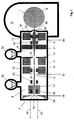
- the device essentially consists of a beam generator 4 generating an electron beam 3, a lens system 5 and a vacuum chamber 6 accommodating the texture roller 2.
- the beam generator 4 and the lens system 5 are arranged in the region of a beam device 7, which is divided into a main chamber 8 and an intermediate chamber 9.
- Arranged in the main chamber 8 are the beam generator 4 and a focal length setting 10, which is designed as part of the lens system 5.
- the main chamber 8 is separated from the intermediate chamber 9 by a vacuum throttle 13 which has a recess 14 which is arranged essentially centrally and allows the passage of the electron beam 3.
- the vacuum throttle 13 makes it possible to provide different pressure ratios in the area of the main chamber 8 and the intermediate chamber 9. For example, it is possible to provide a pressure of approximately 8 x 0.00001 bar in the area of the main chamber 8 and a pressure of approximately 8 x 0.001 bar in the area of the intermediate chamber 9.
- the beam generator 4 essentially consists of a cathode 15, a Wehnelt cylinder 16 and an anode 17. In the area of the anode 17, an electron beam 3 is focused Anode centering device 18 is arranged. In the direction of propagation of the electron beam 3, a follow-up centering device 20 is arranged behind the anode 17, which likewise bundles the electron beam 3 and avoids scattering losses.
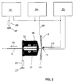
- the cathode 15 is connected via a line 15 'to a high-voltage unit 21 (FIG. 2), which generates a voltage of up to approximately 50 kilovolts. A typical value is around - 35 kilovolts.
- recesses 22 With such a tension, recesses 22 with a typical depth of approximately 7 micrometers per microsecond can be produced in the area of the surface 1.
- the typical depth of the recess 22 (FIG. 4) is approximately 3 to 4 micrometers per microsecond.
- the cathode 15 is also connected to a heating power supply 23 (FIG. 2).
- the Wehnelt cylinder 16 is fed via a line 16 'by a voltage generator 24, which generates a potential of approximately - 1000 volts compared to the voltage applied to the cathode 15.
- an ion trap 25 is provided in the area of the anode 17, in addition to the centering coils forming the anode centering device 18, an ion trap 25 is provided, which derives ions occurring in the area of the anode 17 from the area of the electron beam 3.
- the anode 17 is connected to a ground connection 27 via a resistor 26.
- the high-voltage unit 21 is also connected to ground via a resistor 28 in the region of a reference connection. Tungsten wires are particularly suitable as the material for the cathode 15.
- the focal length setting 10 is constructed from a first zoom lens 29 and a second zoom lens 30, which are arranged one behind the other in the direction of propagation 19 (FIG. 4).
- the first zoom lens 29 consists of a dynamic lens 31 and a static lens 32.
- the second zoom lens 30 is designed without a dynamic lens 31.
- the vacuum in the area of the main chamber 8 is maintained by a vacuum pump 33 and the vacuum in the area of the intermediate chamber 9 by a vacuum pump 34 (FIG. 1).
- a vacuum pump 34 (FIG. 1).
- the pumps 33, 34 are turbomolecular pumps.
- a centering device 35 is provided between the interchangeable aperture 11 and the focusing 12, which avoids scattering losses of the electron beam 3.
- the focusing 12 essentially consists of a static lens 36 and a dynamic lens 37.
- the dynamic lenses 32 and 36 are each arranged in the region of the inner surfaces of the static lenses 32 and 36 facing the electron beam 3.
- the device 7 On the side facing the vacuum chamber 6, the device 7 has an outlet opening 38, in which a nozzle 39 is arranged.
- a raster disk 40 is provided which is synchronized with the rotary movement of the texture roller 2 and which is connected to an evaluation 42 via the pickup 41 (FIG. 3).
- the evaluation 42 provides a clock for subsequent control elements, which enables an exact detection of a current orientation of the texture roller 2.
- a reference point 43 is defined in a defined manner with the aid of a zero point detection.
- the evaluation 42 is connected to a controller 44, which can be designed, for example, as a phase-locked loop circuit.
- the controller 44 feeds a sawtooth generator 45 and a feed stroke generator 46.
- the sawtooth generator 45 has an engraving sawtooth connection 47 and a feed saw tooth connection 48.
- the feed clock generation 46 is provided with a feed stepper motor connection 49.
- the evaluation 42 is connected to the sawtooth generator 45 and via a control connection 50 ' connected to a lens drive 50.
- the lens driver 50 has a zoom lens connector 51, a focus lens connector 52 and a control connector 53.
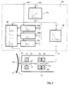
- a plurality of characteristic curve elements for signal shaping are provided in the lens control 50 (FIG. 4).
- a control variable for the electron beam recording element which determines the geometry of the recesses 22 to be produced, is linearized 54 to a focus element 55, to timer stages 56a, 56b and 56c and to a zoom element 58 given.
- the entered control variable is converted in the focus element 55 by means of characteristic curves into setting values for the focusing 12, which are fed to the dynamic lens 37 of the focusing 12.
- the characteristic curve of the zoom element 58 converts the control variable into corresponding setting values for the focal length setting 10, which reach the dynamic lens 31.
- the timing obtained in the evaluation 42 and the sawtooth signal generated in the sawtooth generator 45 are used to coordinate the process sequences in the production of the recesses 22 (FIG. 4).
- the time interval provided for producing a recess 22 corresponds to a period of the sawtooth signal 59 (FIG. 10), the start of a time interval being marked by a clock.
- the time interval comprises at least one working interval 60 and one intermediate interval 61.
- a pre-treatment interval 63 lying before the working interval 60 and / or a post-treatment interval lying behind the working interval 60 is also preferred 64 provided (Fig. 10).
- the focusing 12 is controlled in such a way that the electron beam 3 has an energy density which produces the recess 22 or enlarges it.
- the pretreatment interval 63 the area occupied by the recess 22 and the crater wall 62 is cleaned and preheated.
- the pretreatment ensures a permanent connection of the crater wall 62 to the surface 1.
- the crater wall 62 melts for a defined period of time.
- the respective duration of the working interval 60, the pretreatment interval 63 and / or the aftertreatment interval 64 is determined in the timer stages 56a, 56b and 56c of the lens control 50 (FIG. 4) as a function of the control variable by the control variable using characteristic curves in the respective Time duration of the intervals determining clock signals are converted.
- the timer stage 56a which determines the duration of the pretreatment interval 63, is triggered by the clock at the control connection 50 '.
- the timer stage 56b which defines the duration of the work interval 60, is activated by the timer stage 56a.
- the timer stage 56c which determines the duration of the aftertreatment interval 64, is started by the timer stage 56b.
- the clock signals obtained in the timer stages 56a, 56b and 56c are fed to the sharpness element 55 and control the output of the different setting values for the focusing 12 in the pre-treatment interval 63, in the working interval 60 and / or in the after-treatment interval 64.
- the relative movement of the texture roller 2 with respect to the nozzle 39 can be compensated for by tracking the electron beam 3.
- the electron beam 3 remains precisely aligned with a preselected area and leads to the formation of very symmetrical recesses 22. Due to the very short time delays in the actuation of the lens system 5, approximately 150,000 recesses 22 can be produced per second.
- a complete texture roller 2 can be positioned within of about 45 minutes.
- the energy consumption by the textured roller is only about 500 watts during this time. Unwanted changes in the area of the surface 1 due to thermal tension or similar processes are therefore excluded with a high degree of probability.
- a period of approximately one microsecond has proven to be expedient as a time period for the intermediate interval 61.
- An area with a diameter of approximately 30-400 micrometers is occupied by the recess 22 and the crater wall 62.
Landscapes
- Engineering & Computer Science (AREA)
- Chemical & Material Sciences (AREA)
- Mechanical Engineering (AREA)
- Physics & Mathematics (AREA)
- Thermal Sciences (AREA)
- Crystallography & Structural Chemistry (AREA)
- Materials Engineering (AREA)
- Metallurgy (AREA)
- Organic Chemistry (AREA)
- Welding Or Cutting Using Electron Beams (AREA)
- Cleaning In General (AREA)
- Reduction Rolling/Reduction Stand/Operation Of Reduction Machine (AREA)
Abstract
Claims (7)
- Procédé de fabrication de cylindres à texturer comportant une structure superficielle sous la forme d'évidements (22), procédé dans lequel les évidements (22) qui se trouvent à la surface (1) des cylindres à texturer (2) sont produits dans certains intervalles de temps à l'aide d'un faisceau électronique (3), caractérisé en ce que les intervalles de temps sont respectivement subdivisés en au moins deux intervalles de travail (60) séparés l'un de l'autre par un intervalle intermédiaire (61) et en ce que la surface (1) est alimentée pendant les intervalles de travail (60) par le faisceau électronique (3), respectivement, avec une densité d'énergie produisant les évidements (22) et, dans l'intervalle intermédiaire (61), avec une densité d'énergie qui ne change sensiblement pas la dimension des évidements (22).
- Procédé selon la revendication 1, caractérisé en ce que la densité d'énergie du faisceau électronique (3) est modifiée à l'aide d'un dispositif de focalisation (12) et en ce que la densité d'énergie au cours de l'intervalle intermédiaire (61) est réduite par défocalisation par rapport à la focalisation règlée pendant les intervalles de travail (60).
- Procédé selon la revendication 1 ou 2, caractérisé en ce qu'une mise au point du faisceau électronique (3) est effectuée autant au cours de l'intervalle de travail (60) qu'au cours de l'intervalle intermédiaire (61).
- Procédé selon l'une quelconque des revendications 1 à 3, caractérisé en ce qu'on réalise, dans des intervalles de prétraitement (63) qui se situent avant les intervalles de travail (60), à l'aide du faisceau électronique (3), une augmentation de température et un nettoyage de la surface (1) respectivement dans une zone correspondant à l'évidement (22) et au bord (62) du cratère.
- Procédé selon l'une quelconque des revendications 1 à 4, caractérisé en ce que l'on effectue, dans des intervalles de post-traitement (64) qui se situent après les intervalles de travail (60), à l'aide du faisceau électronique (3), respectivement, dans la zone de l'évidement (22) et de la paroi (62) du cratère, une fusion de la paroi (62) du cratère.
- Procédé selon l'une quelconque des revendications 1 à 5, caractérisé en ce que la structure superficielle à la surface (1) du cylindre à texturer (2) est produite par un mouvement relatif entre le cylindre à texturer (2) et un générateur de faisceau générant le faisceau électronique (3) et en ce que le faisceau électronique (3) est guidé selon le mouvement relatif au moins pendant les intervalles de travail (60).
- Dispositif pour réaliser le procédé selon l'une quelconque des revendications 1 à 6, constitué d'une chambre à vide (6) recevant le cylindre à texturer (2) et d'un dispositif de production de faisceau (7) relié à la chambre à vide (6), lequel dispositif est constitué d'un générateur de faisceau (4) pour produire le faisceau électronique (3), d'un dispositif de réglage de foyer (10) avec un premier système de lentilles (29) à grande distance focale possédant une lentille statique (32) et une lentille dynamique (31) et d'un deuxième système de lentilles à distance focale courte (30), d'un dispositif de focalisation (12) avec un troisième système de lentilles possèdent une lentille statique (36) et une lentille dynamique (37), d'un premier dispositif de commande (21; 23; 24) relié au générateur de faisceau (4) et d'un deuxième dispositif de commande (42, 44, 45, 46, 50) relié au dispositif de réglage de foyer (10) et au dispositif de focalisation (12), caractérisé en ce que le deuxième dispositif de commande présente un dispositif de synchronisation (55, 56a, 56b, 56c) relié au dispositif de réglage de foyer (10) et/ou au dispositif de focalisation (12) pour commander la densité d'énergie du faisceau électronique (3) dans les intervalles de prétraitement (63), dans les intervalles de travail (60), dans les intervalles intermédiaires (61) et dans les intervalles de post-traitement (64) par réglage de la lentille dynamique (31) et/ou de la lentille dynamique (37).
Applications Claiming Priority (3)
| Application Number | Priority Date | Filing Date | Title |
|---|---|---|---|
| DE4031547 | 1990-10-05 | ||
| DE4031547A DE4031547A1 (de) | 1990-10-05 | 1990-10-05 | Verfahren und vorrichtung zur herstellung von texturwalzen |
| PCT/DE1991/000786 WO1992005911A1 (fr) | 1990-10-05 | 1991-10-03 | Procede et dispositif pour la fabrication de cylindres de texturisation |
Publications (2)
| Publication Number | Publication Date |
|---|---|
| EP0504352A1 EP0504352A1 (fr) | 1992-09-23 |
| EP0504352B1 true EP0504352B1 (fr) | 1994-05-11 |
Family
ID=6415653
Family Applications (1)
| Application Number | Title | Priority Date | Filing Date |
|---|---|---|---|
| EP91917190A Expired - Lifetime EP0504352B1 (fr) | 1990-10-05 | 1991-10-03 | Procede et dispositif pour la fabrication de cylindres de texturisation |
Country Status (6)
| Country | Link |
|---|---|
| US (1) | US5438179A (fr) |
| EP (1) | EP0504352B1 (fr) |
| JP (1) | JP2600039B2 (fr) |
| AU (1) | AU8544391A (fr) |
| DE (2) | DE4031547A1 (fr) |
| WO (1) | WO1992005911A1 (fr) |
Families Citing this family (4)
| Publication number | Priority date | Publication date | Assignee | Title |
|---|---|---|---|---|
| DE69501137T2 (de) | 1994-09-14 | 1998-04-09 | Shinetsu Chemical Co | Verfahren zur Herstellung von einem Vinyl-Chlorid-Typ Polymer |
| KR100340945B1 (ko) * | 1999-12-23 | 2002-06-20 | 장인순 | 전자빔을 이용한 천공장치 |
| US6530317B2 (en) | 2000-12-05 | 2003-03-11 | Creo Srl | Method to engrave surface using particle beam |
| US6881282B2 (en) * | 2001-03-02 | 2005-04-19 | Ford Motor Company | Method of manufacturing a chromed bumper |
Family Cites Families (20)
| Publication number | Priority date | Publication date | Assignee | Title |
|---|---|---|---|---|
| DE195730C (fr) * | ||||
| FR902850A (fr) * | 1943-03-27 | 1945-09-13 | Lorenz C Ag | Mandrin de guidage pour machine à spiraler utilisée dans la fabrication de filaments de chauffage pour cathodes |
| IT559958A (fr) * | 1955-07-06 | 1900-01-01 | ||
| US3340601A (en) * | 1963-07-17 | 1967-09-12 | United Aircraft Corp | Alloy diffused transistor |
| DE1301209B (de) * | 1964-07-24 | 1969-08-14 | Steigerwald Strahltech | Verfahren zum Abtragen, insbesondere zum Perforieren von flexiblen Kunststoffen |
| US3404254A (en) * | 1965-02-26 | 1968-10-01 | Minnesota Mining & Mfg | Method and apparatus for engraving a generally cross-sectionally circular shaped body by a corpuscular beam |
| FR1518224A (fr) * | 1966-04-08 | 1968-03-22 | Philips Nv | Procédé pour forer un trou à l'aide d'un faisceau de rayons, riche en énergie |
| NL6604805A (fr) * | 1966-04-08 | 1967-10-09 | ||
| GB1410518A (en) * | 1972-10-30 | 1975-10-15 | Crosfield Electronics Ltd | Preparation of printing surfaces |
| DE2458370C2 (de) * | 1974-12-10 | 1984-05-10 | Dr.-Ing. Rudolf Hell Gmbh, 2300 Kiel | Energiestrahl-Gravierverfahren und Einrichtung zu seiner Durchführung |
| DE2840702A1 (de) * | 1977-09-22 | 1979-04-05 | Centre Rech Metallurgique | Verfahren und vorrichtung zur qualitaetsverbesserung von stahlfeinblechen |
| DE2947444C2 (de) * | 1979-11-24 | 1983-12-08 | Dr.-Ing. Rudolf Hell Gmbh, 2300 Kiel | Elektronenstrahl-Gravierverfahren |
| DE3175839D1 (en) * | 1981-10-10 | 1987-02-19 | Hell Rudolf Dr Ing Gmbh | Electron beam engraving method and apparatus for carrying it out |
| DE3240654A1 (de) * | 1982-11-04 | 1984-05-10 | Dr.-Ing. Rudolf Hell Gmbh, 2300 Kiel | Verfahren zum ortsgeneuen nachgravieren von druckzylindern |
| DE3240653A1 (de) * | 1982-11-04 | 1984-05-10 | Dr.-Ing. Rudolf Hell Gmbh, 2300 Kiel | Verfahren zur kontrolle von mittels elektronenstrahlgravierten druckformoberflaechen |
| LU84687A1 (fr) * | 1983-03-11 | 1984-11-14 | Centre Rech Metallurgique | Procede pour ameliorer l'etat de surface d'un cylindre |
| FR2568154B1 (fr) * | 1984-07-30 | 1987-07-17 | United Technologies Corp | Appareil de forage de trous par faisceaux d'electrons |
| JPS6272494A (ja) * | 1985-09-25 | 1987-04-03 | Anritsu Corp | レ−ザ加工機 |
| JPS63177978A (ja) * | 1987-01-16 | 1988-07-22 | Mitsubishi Electric Corp | 圧延用ロ−ラの粗面化装置 |
| DE4031546A1 (de) * | 1990-10-05 | 1992-04-09 | Hell Rudolf Dr Ing Gmbh | Verfahren und vorrichtung zur herstellung einer texturwalze |
-
1990
- 1990-10-05 DE DE4031547A patent/DE4031547A1/de not_active Withdrawn
-
1991
- 1991-10-03 EP EP91917190A patent/EP0504352B1/fr not_active Expired - Lifetime
- 1991-10-03 US US08/030,459 patent/US5438179A/en not_active Expired - Fee Related
- 1991-10-03 DE DE59101614T patent/DE59101614D1/de not_active Expired - Fee Related
- 1991-10-03 WO PCT/DE1991/000786 patent/WO1992005911A1/fr not_active Ceased
- 1991-10-03 JP JP3515446A patent/JP2600039B2/ja not_active Expired - Fee Related
- 1991-10-03 AU AU85443/91A patent/AU8544391A/en not_active Abandoned
Also Published As
| Publication number | Publication date |
|---|---|
| DE4031547A1 (de) | 1992-04-09 |
| EP0504352A1 (fr) | 1992-09-23 |
| WO1992005911A1 (fr) | 1992-04-16 |
| US5438179A (en) | 1995-08-01 |
| JPH06501884A (ja) | 1994-03-03 |
| JP2600039B2 (ja) | 1997-04-16 |
| DE59101614D1 (de) | 1994-06-16 |
| AU8544391A (en) | 1992-04-28 |
Similar Documents
| Publication | Publication Date | Title |
|---|---|---|
| DE4200632C2 (de) | Verfahren und Vorrichtung zum Bearbeiten von Werkstücken mittels der von einem Laser emittierten Laserstrahlung | |
| DE2458370C2 (de) | Energiestrahl-Gravierverfahren und Einrichtung zu seiner Durchführung | |
| DE60025600T2 (de) | Verfahren zur bolzenschweissen mit einer reinigungsstufe | |
| EP0551333B1 (fr) | Procede pour la fabrication d'un cylindre de texturation | |
| EP4415919B1 (fr) | Procédé de soudage laser d'une pièce, à changement rapide entre des zones de soudage comportant des matériaux à souder différents | |
| EP0551316B1 (fr) | Procede pour la fabrication d'un cylindre de texturisation | |
| EP0029604B1 (fr) | Procédé de gravure utilisant un faisceau d'électrons | |
| DE60102597T2 (de) | Laser mit hoher spitzenleistung und dessen anwendung zur erzeugung von licht im extrem-uv-bereich | |
| WO2001051241A1 (fr) | Procede et dispositif de soudage a l'arc en plusieurs etapes | |
| DE69215855T2 (de) | Verfahren zum laserdurchbohren | |
| DE4102984A1 (de) | Oberflaechenstruktur einer walze sowie verfahren und vorrichtung zur erzeugung der oberflaechenstruktur | |
| DE4102983A1 (de) | Oberflaechenstruktur einer walze sowie verfahren und vorrichtung zur erzeugung der oberflaechenstruktur | |
| DE4031547A1 (de) | Verfahren und vorrichtung zur herstellung von texturwalzen | |
| DE3121555C2 (de) | Verfahren zum Bearbeiten von Stahl mittels Laserstrahlung | |
| EP0561975B1 (fr) | Procede pour l'exploitation, avec un entretien reduit, d'un dispositif pour la realisation d'une structure de surface, et dispositif | |
| DE102016208131B4 (de) | Verfahren und Vorrichtung zum Bearbeiten eines Werkstücks | |
| WO2018234192A1 (fr) | Système et procédé pour usiner une surface | |
| DE102004041502B4 (de) | Überlappschweißverfahren mittels Strahlschweißung, insbesondere mittels Laserstrahlschweißung, an beschichteten Blechen, insbesondere an verzinkten Stahlblechen | |
| DE102005017294A1 (de) | Laserstrahlbearbeitungseinrichtung und Verfahren zum Bearbeiten mittels Laserstrahl | |
| JP2600040B2 (ja) | ワークロールの製造方法および製造装置 | |
| DE19634304A1 (de) | Verfahren und Vorrichtung zur Erzeugung von Elektronenstrahlen | |
| DE4032918A1 (de) | Verfahren und vorrichtung zur abschirmung eines elektronenstrahles |
Legal Events
| Date | Code | Title | Description |
|---|---|---|---|
| PUAI | Public reference made under article 153(3) epc to a published international application that has entered the european phase |
Free format text: ORIGINAL CODE: 0009012 |
|
| 17P | Request for examination filed |
Effective date: 19920521 |
|
| AK | Designated contracting states |
Kind code of ref document: A1 Designated state(s): DE FR GB |
|
| 17Q | First examination report despatched |
Effective date: 19930929 |
|
| GRAA | (expected) grant |
Free format text: ORIGINAL CODE: 0009210 |
|
| AK | Designated contracting states |
Kind code of ref document: B1 Designated state(s): DE FR GB |
|
| REF | Corresponds to: |
Ref document number: 59101614 Country of ref document: DE Date of ref document: 19940616 |
|
| ET | Fr: translation filed | ||
| GBT | Gb: translation of ep patent filed (gb section 77(6)(a)/1977) |
Effective date: 19940818 |
|
| RAP2 | Party data changed (patent owner data changed or rights of a patent transferred) |
Owner name: SIDMAR N.V. |
|
| PLBE | No opposition filed within time limit |
Free format text: ORIGINAL CODE: 0009261 |
|
| STAA | Information on the status of an ep patent application or granted ep patent |
Free format text: STATUS: NO OPPOSITION FILED WITHIN TIME LIMIT |
|
| 26N | No opposition filed | ||
| REG | Reference to a national code |
Ref country code: GB Ref legal event code: 732E |
|
| REG | Reference to a national code |
Ref country code: GB Ref legal event code: 732E |
|
| REG | Reference to a national code |
Ref country code: FR Ref legal event code: TP |
|
| REG | Reference to a national code |
Ref country code: FR Ref legal event code: TP |
|
| REG | Reference to a national code |
Ref country code: GB Ref legal event code: IF02 |
|
| PGFP | Annual fee paid to national office [announced via postgrant information from national office to epo] |
Ref country code: GB Payment date: 20050929 Year of fee payment: 15 |
|
| PGFP | Annual fee paid to national office [announced via postgrant information from national office to epo] |
Ref country code: DE Payment date: 20051004 Year of fee payment: 15 |
|
| PGFP | Annual fee paid to national office [announced via postgrant information from national office to epo] |
Ref country code: FR Payment date: 20051027 Year of fee payment: 15 |
|
| PG25 | Lapsed in a contracting state [announced via postgrant information from national office to epo] |
Ref country code: DE Free format text: LAPSE BECAUSE OF NON-PAYMENT OF DUE FEES Effective date: 20070501 |
|
| GBPC | Gb: european patent ceased through non-payment of renewal fee |
Effective date: 20061003 |
|
| REG | Reference to a national code |
Ref country code: FR Ref legal event code: ST Effective date: 20070629 |
|
| PG25 | Lapsed in a contracting state [announced via postgrant information from national office to epo] |
Ref country code: GB Free format text: LAPSE BECAUSE OF NON-PAYMENT OF DUE FEES Effective date: 20061003 |
|
| PG25 | Lapsed in a contracting state [announced via postgrant information from national office to epo] |
Ref country code: FR Free format text: LAPSE BECAUSE OF NON-PAYMENT OF DUE FEES Effective date: 20061031 |