EP0504606A1 - Dispositif de commande du moteur d'essuie-glace d'un véhicule automobile - Google Patents
Dispositif de commande du moteur d'essuie-glace d'un véhicule automobile Download PDFInfo
- Publication number
- EP0504606A1 EP0504606A1 EP92102816A EP92102816A EP0504606A1 EP 0504606 A1 EP0504606 A1 EP 0504606A1 EP 92102816 A EP92102816 A EP 92102816A EP 92102816 A EP92102816 A EP 92102816A EP 0504606 A1 EP0504606 A1 EP 0504606A1
- Authority
- EP
- European Patent Office
- Prior art keywords
- switch
- interval
- automatic
- pause time
- speed
- Prior art date
- Legal status (The legal status is an assumption and is not a legal conclusion. Google has not performed a legal analysis and makes no representation as to the accuracy of the status listed.)
- Granted
Links
Images


Classifications
-
- B—PERFORMING OPERATIONS; TRANSPORTING
- B60—VEHICLES IN GENERAL
- B60S—SERVICING, CLEANING, REPAIRING, SUPPORTING, LIFTING, OR MANOEUVRING OF VEHICLES, NOT OTHERWISE PROVIDED FOR
- B60S1/00—Cleaning of vehicles
- B60S1/02—Cleaning windscreens, windows or optical devices
- B60S1/04—Wipers or the like, e.g. scrapers
- B60S1/06—Wipers or the like, e.g. scrapers characterised by the drive
- B60S1/08—Wipers or the like, e.g. scrapers characterised by the drive electrically driven
- B60S1/0896—Wipers or the like, e.g. scrapers characterised by the drive electrically driven including control systems responsive to a vehicle driving condition, e.g. speed
-
- B—PERFORMING OPERATIONS; TRANSPORTING
- B60—VEHICLES IN GENERAL
- B60S—SERVICING, CLEANING, REPAIRING, SUPPORTING, LIFTING, OR MANOEUVRING OF VEHICLES, NOT OTHERWISE PROVIDED FOR
- B60S1/00—Cleaning of vehicles
- B60S1/02—Cleaning windscreens, windows or optical devices
- B60S1/04—Wipers or the like, e.g. scrapers
- B60S1/06—Wipers or the like, e.g. scrapers characterised by the drive
- B60S1/08—Wipers or the like, e.g. scrapers characterised by the drive electrically driven
- B60S1/0803—Intermittent control circuits
- B60S1/0807—Intermittent control circuits using electronic control means, e.g. tubes, semiconductors
-
- B—PERFORMING OPERATIONS; TRANSPORTING
- B60—VEHICLES IN GENERAL
- B60S—SERVICING, CLEANING, REPAIRING, SUPPORTING, LIFTING, OR MANOEUVRING OF VEHICLES, NOT OTHERWISE PROVIDED FOR
- B60S1/00—Cleaning of vehicles
- B60S1/02—Cleaning windscreens, windows or optical devices
- B60S1/04—Wipers or the like, e.g. scrapers
- B60S1/06—Wipers or the like, e.g. scrapers characterised by the drive
- B60S1/08—Wipers or the like, e.g. scrapers characterised by the drive electrically driven
- B60S1/0818—Wipers or the like, e.g. scrapers characterised by the drive electrically driven including control systems responsive to external conditions, e.g. by detection of moisture, dirt or the like
Definitions
- the invention relates to a control device for windshield wiper operation of a motor vehicle.
- Simple windshield wiper controls usually result in the following wiping modes of operation by means of a corresponding manual call-up using an operating mode switch, namely in level 1 interval operation, in level 2 continuous operation and possibly in level 3, continuous operation with a higher wiping speed.
- windshield wiper controls are also known in which the wiping operation is regulated by means of an in-vehicle computer either as a function of the driving speed or a degree of wetness detected in the area of the windshield.
- these automatic solutions can only partially satisfy. The latter is because there are certain driving conditions which, in connection with particularly critical weather conditions, cannot be taken into account by said automatic programs.
- control device specified in claim 1 which is to be understood as a combination of all the components specified there in connection with the specified operating options.
- the solution according to the invention allows the driver the greatest possible freedom with regard to the individually desired wiping mode of operation by manual setting of the same via the operating mode switch and the preselection element.
- the driver has the option of calling up various automatic programs, whereupon a corresponding wiping mode of operation is regulated by computer depending on the driving speed and / or a detected degree of wetness.
- the driver has the option of exiting the set automatic program at any time, for example in the case of seriously changing driving situations or extremely rapidly changing weather conditions, and then immediately manually setting the desired wiping mode again.
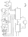
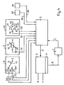
- the control device for the wiper operation of the windshield of a motor vehicle by means of one or more wipers comprises a wiper motor 1 (FIG. 2 to 4) or, as shown in FIG. 1, for each wiper linkage, with a linkage driving the wiper motor - Its own wiper motor 1, 1a and a computer 2 and a further control unit 3 with power section 4 for controlling the wiper motor operation.
- Computer 2 and control unit 3 can be implemented as separate components or in one another or assembled to form a structural unit.
- the computer 2 can be an independent component that only serves to regulate the wiping operation or the on-board computer which may be present in the vehicle and which, among other things, also takes over the wiping operation control.
- Such a computer is known in its general structure, it consists of a microprocessor (CPU), data and Program memories and an input and output periphery, which parts are linked internally via a corresponding BUS system.
- the control unit 3 is used for starting and braking control as well as for setting the speed or speed of the wiper motor 1.
- the control unit 3 works on the basis of commands which are supplied to it by the computer 2 via the control line 5.
- the output commands of the control unit 3 are amplified accordingly by the power unit 4 and fed via line 6 to the wiper motor 1 or via lines 6, 6a to the wiper motors 1, 1a, which then converts them into a corresponding operating mode.
- the function of the wiper motor 1 or the wiper motors 1, 1a is monitored by the computer 2, which receives the corresponding control signals via line 7 or lines 7, 7a.
- the organs 8, 9 10 can be realized on and in connection with a steering column shift lever 12 given in the area of the steering wheel 11 of the vehicle, as can be seen in FIG.
- the shift finger 13 of the mode switch 8 is arranged at the inner end of the steering column switch lever 12, while the switch contacts 15, 26, 27 associated with the individual switch positions (0-1-2) of the mode switch 8 are arranged on the steering column of the steering wheel 11.
- the actuation of the steering column shift lever 12 for setting the operating mode switch 8 in its different switching positions (0-1-2) is indicated by arrow 14.
- the pre-selection element 9 is formed by an adjusting sleeve 16 which is arranged on the outer end region of the steering column shift lever 12 and can be rotated in the direction of arrow 15 between a zero and maximum position and has a sliding contact 17 on the inside (see FIGS. 1-3) , which forms a potentiometer or the like with a steering column shift lever-mounted resistor 18.
- the automatic on / off switch 10 is realized by a push button 19, which can be actuated in the direction of the arrow 20 and is provided on the outside at the end of the steering column switch lever 12 and on the inside with a switch contact 21 (see FIGS. 1 to 3) or two switch contacts 21, 22 (see Fig. 4), which is equipped with a Counter-contact 23 provided on the steering-column switching lever or which can be or are connected to two counter-contacts 23, 24 provided on the steering column switching lever.
- the automatic on-off switch 10 can be designed as a pushbutton switch or as a switch which can be locked in the respective switching position, in the latter case the locking would have to be ensured via the push button 19 and the steering column switch lever 12 by means of corresponding latching elements.
- the switching contacts 25, 26, 27 belonging to the individual switching positions (0-1-2) of the mode switch 8 are each via a line 28, 29, 30, the connection 28 of the potentiometer 17, 18 forming the preselection element 9 is via line 29 and Terminal 30 or the terminals 30, 31 of the automatic on / off switch 10 is or are connected to the computer 2 via line 32 or 33.
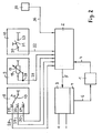
- a speed sensor 35 connected via line 34 to the computer 2 (detects and reports driving speed) and additionally (as can be seen in FIGS. 3 and 4) or instead of the latter (as can be seen in FIG. 2) can be mentioned Moisture sensor 37 connected to the computer 2 via line 36 and detecting the degree of wetness in the area of the windshield or another suitable location.
- the automatic program mentioned above under point c) is adapted to the type of vehicle (car, truck, bus) and its specific, characteristic mode of operation.
- a different automatic program can be used for a car with a maximum speed of 140 km / h than for a car designed for a maximum speed of 200 or more km / h.
- the same applies to a city bus compared to a touring coach or only for distribution traffic used truck compared to a long-distance truck mainly used on long distances.
- the 1 refers to a control device, in the computer 2 of which at least one automatic program for the wiping operation, which operates as a function of the vehicle speed and is adapted to the vehicle and application, is stored.
- This automatic program is suitable, for example, for use in a long-distance truck or touring coach, but also in a car designed for a maximum speed of up to 140 km / h.
- This automatic program can be used universally, since extra-local driving speeds are basically decisive as a reference variable for increasing or reducing the wiping speed.
- an automatic program which, in addition to one of the two aforementioned automatic programs or alone, can be stored in the computer 2 and relates to an even more sensitive setting of the interval wiping operation.
- an automatic program is provided which can be used instead of that according to the third case described above and, like the latter, in addition to one of the first two (cases 1 and 2) automatic programs or alone in the computer 2 is stored and causes a seamless transition from a manually set interval wiping to the automatically controlled.
- the computer 2 then initiates a continuation of the interval operation with that pause time corresponding to the manual preselection with the preselection element 9, an interval operation with shorter pause times when the driving speed increases, or an interval operation with longer pause times when the driving speed then decreases.
- the driver e.g. if he wishes a transition to continuous wiping or considers it necessary, exit this automatic program in the same way and with the same continuations as described in connection with case 3.
- an automatic program can be provided, which is stored in the computer 2 in addition to one of the first two (cases 1 or 2) and one of the two following (cases 3 or 4) or also alone and only concerns a speed-dependent regulation of the continuous wiping operation.
- Computer 2 will then at V ⁇ V4 (60 km / h)> V3 a slow continuous operation, at V ⁇ V5 (80 km / h)> V4 a faster continuous operation, and with V> V5 the fastest continuous operation initiated.
- the driver can also completely exit the automatic programs, whereupon he then actuates the preselector 9 desired interval time for interval operation.
- an automatic program can also be provided, which is explained below as the sixth case related to FIG. 1.
- This automatic program can also be stored in the computer 2 in addition to one of the first two (cases 1 or 2) and one of the two following (cases 3 or 4) or alone and causes a seamless transition from a manually set continuous wiping mode to an automatically controlled one .
- the computer 2 first continues the continuous wiping operation with that corresponding to the manual preselection with the preselection element 9, and then increases the driving speed step-by-step or stepless increase in the wiping speed or, in the event of a subsequently decreasing driving speed, a step-by-step or stepless reduction of the wiping speed which goes to a non-zero minimum.
- the driver can exit this automatic program in the same way and with the same continuations as described in connection with case 5.
- FIG. 2 refers to a control device, in the computer 2 of which an automatic program that only depends on the degree of wetness is stored.
- the computer 2 When it is called up by the driver by actuating the automatic on / off switch 10 - with the operating mode switch 8 and preselection element 9 located in any position - the computer 2 intermittently operates in the event of low wetness with a certain pause time, in medium wet conditions intermittent operation with shorter pause times greater wetness, a transition from interval to slow continuous operation and, in the case of wetness that continues to increase to a maximum, an increase in the permanent wiping speed by appropriate regulation of the wiper motor speed up to n max .
- the driver can exit this automatic program, either by actuating the automatic on / off switch 10 again and / or by adjusting the operating mode switch 8 to a setting position other than that specified.
- the automatic on-off switch 10 also function in a different way than described above and can also be formed and arranged separately from the organs 8 and 9, for example as in the area of the dashboard or Independent pushbutton or slide switch in the area of the steering wheel, to which, in particular, a digital program display, in particular, can also be assigned.
Landscapes
- Engineering & Computer Science (AREA)
- Mechanical Engineering (AREA)
- Automation & Control Theory (AREA)
- Control Of Direct Current Motors (AREA)
- Control Of Driving Devices And Active Controlling Of Vehicle (AREA)
Applications Claiming Priority (2)
| Application Number | Priority Date | Filing Date | Title |
|---|---|---|---|
| DE4109318A DE4109318A1 (de) | 1991-03-21 | 1991-03-21 | Steuereinrichtung fuer den scheibenwischbetrieb eines kraftfahrzeuges |
| DE4109318 | 1991-03-21 |
Publications (2)
| Publication Number | Publication Date |
|---|---|
| EP0504606A1 true EP0504606A1 (fr) | 1992-09-23 |
| EP0504606B1 EP0504606B1 (fr) | 1995-03-29 |
Family
ID=6427900
Family Applications (1)
| Application Number | Title | Priority Date | Filing Date |
|---|---|---|---|
| EP92102816A Expired - Lifetime EP0504606B1 (fr) | 1991-03-21 | 1992-02-20 | Dispositif de commande du moteur d'essuie-glace d'un véhicule automobile |
Country Status (2)
| Country | Link |
|---|---|
| EP (1) | EP0504606B1 (fr) |
| DE (2) | DE4109318A1 (fr) |
Cited By (10)
| Publication number | Priority date | Publication date | Assignee | Title |
|---|---|---|---|---|
| WO1996008395A1 (fr) * | 1994-09-13 | 1996-03-21 | Itt Automotive Electrical Systems, Inc. | Dispositifs generiques de commande d'essuie-glace |
| NL1000031C2 (nl) * | 1995-04-04 | 1996-10-07 | Netherlands Car Bv | Stuurschakeling. |
| FR2743769A1 (fr) * | 1996-01-19 | 1997-07-25 | Bosch Gmbh Robert | Dispositif servant a faire fonctionner un essuie-glace avec une commande automatique de l'essuie-glace |
| EP0803413A3 (fr) * | 1996-04-25 | 1998-03-04 | Eaton Corporation | Commande d'essuie-glace de pare-brise avec protection contre blocage |
| WO1999032335A1 (fr) * | 1997-12-19 | 1999-07-01 | Daimlerchrysler Ag | Systeme de commande pour essuie-glace |
| EP0987154A3 (fr) * | 1998-09-19 | 2002-07-03 | Siemens Aktiengesellschaft | Essuie-glace pour un véhicule |
| WO2005023610A1 (fr) * | 2003-09-03 | 2005-03-17 | Daimlerchrysler Ag | Dispositif de commande d'essuie-glace |
| EP1577183A1 (fr) * | 2004-03-16 | 2005-09-21 | Delphi Technologies, Inc. | Dispositif d'essuie-glace et méthode d'essuyage d'une vitre |
| CN103625431A (zh) * | 2013-12-17 | 2014-03-12 | 周云侠 | 汽车雨刮无触点控制器 |
| CN115107707A (zh) * | 2022-06-24 | 2022-09-27 | 重庆长安汽车股份有限公司 | 一种电子雨刮控制系统 |
Families Citing this family (11)
| Publication number | Priority date | Publication date | Assignee | Title |
|---|---|---|---|---|
| US5254916A (en) * | 1992-07-31 | 1993-10-19 | Sgs-Thomson Microelectronics, Inc. | Windshield wiper speed and delay control |
| US5519258A (en) * | 1993-11-22 | 1996-05-21 | Ford Motor Company | System and method for controlling vehicle lift gate window wiper |
| DE19536621C2 (de) * | 1995-09-30 | 2000-11-23 | Bayerische Motoren Werke Ag | Vorrichtung zur elektronischen Steuerung eines Scheibenwischers bei Kraftfahrzeugen |
| GB2311208A (en) * | 1996-03-21 | 1997-09-24 | Rover Group | A wiper system |
| DE19725351C1 (de) * | 1997-06-16 | 1998-10-22 | Daimler Benz Ag | Steuereinrichtung für den Betrieb eines Scheibenwischers in einem Kraftfahrzeug |
| DE10118173B4 (de) * | 2001-04-11 | 2014-02-13 | Volkswagen Ag | Wischersteuerung |
| JP4205032B2 (ja) * | 2004-09-14 | 2009-01-07 | 本田技研工業株式会社 | 車両用オートワイパーシステム |
| WO2008084577A1 (fr) * | 2007-01-10 | 2008-07-17 | Sumitomo Wiring Systems, Ltd. | Circuit de commande d'essuie-glace |
| CN102381287A (zh) * | 2011-10-18 | 2012-03-21 | 奇瑞汽车股份有限公司 | 一种汽车挡风玻璃清洗装置及其控制方法 |
| CN109334609A (zh) * | 2017-11-21 | 2019-02-15 | 徐育 | 一种雨刮器智能控制方法及装置 |
| DE102017131071A1 (de) * | 2017-12-22 | 2019-06-27 | Valeo Wischersysteme Gmbh | Verfahren zum Betreiben einer Wischanlage und Wischanlage |
Citations (5)
| Publication number | Priority date | Publication date | Assignee | Title |
|---|---|---|---|---|
| DE3008946A1 (de) * | 1980-03-08 | 1981-09-24 | Brown, Boveri & Cie Ag, 6800 Mannheim | Programmierbarer scheibenwischer-intervallschalter |
| DE3021877A1 (de) * | 1980-06-11 | 1981-12-24 | Bayerische Motoren Werke AG, 8000 München | Schaltanordnung fuer den intervallbetrieb eines scheibenwischermotors von kraftfahrzeugen |
| DE3327373C1 (de) * | 1983-07-29 | 1984-12-20 | Leopold Kostal GmbH & Co KG, 5880 Lüdenscheid | Scheibenwischeinrichtung für Kraftfahrzeuge |
| GB2231406A (en) * | 1988-12-24 | 1990-11-14 | Peter Julian Gardner Field | Automatically actuated windscreen wipers |
| EP0399217A2 (fr) * | 1989-05-20 | 1990-11-28 | Daimler-Benz Aktiengesellschaft | Procédé pour commander un moteur d'entraînement d'une installation d'essuie-glace de véhicule automobile |
Family Cites Families (3)
| Publication number | Priority date | Publication date | Assignee | Title |
|---|---|---|---|---|
| US3487282A (en) * | 1967-05-03 | 1969-12-30 | Ford Motor Co | Control system for an electric motor |
| DE186178T1 (de) * | 1984-12-26 | 1986-12-18 | Asmo Co., Ltd., Kosai, Shizuoka | Verdeckte wischeranordnung. |
| FR2648096B1 (fr) * | 1989-06-12 | 1991-08-23 | Valeo Systemes Dessuyage | Systeme d'essuie-glace avec detecteur de pluie |
-
1991
- 1991-03-21 DE DE4109318A patent/DE4109318A1/de active Granted
-
1992
- 1992-02-20 EP EP92102816A patent/EP0504606B1/fr not_active Expired - Lifetime
- 1992-02-20 DE DE59201745T patent/DE59201745D1/de not_active Expired - Fee Related
Patent Citations (5)
| Publication number | Priority date | Publication date | Assignee | Title |
|---|---|---|---|---|
| DE3008946A1 (de) * | 1980-03-08 | 1981-09-24 | Brown, Boveri & Cie Ag, 6800 Mannheim | Programmierbarer scheibenwischer-intervallschalter |
| DE3021877A1 (de) * | 1980-06-11 | 1981-12-24 | Bayerische Motoren Werke AG, 8000 München | Schaltanordnung fuer den intervallbetrieb eines scheibenwischermotors von kraftfahrzeugen |
| DE3327373C1 (de) * | 1983-07-29 | 1984-12-20 | Leopold Kostal GmbH & Co KG, 5880 Lüdenscheid | Scheibenwischeinrichtung für Kraftfahrzeuge |
| GB2231406A (en) * | 1988-12-24 | 1990-11-14 | Peter Julian Gardner Field | Automatically actuated windscreen wipers |
| EP0399217A2 (fr) * | 1989-05-20 | 1990-11-28 | Daimler-Benz Aktiengesellschaft | Procédé pour commander un moteur d'entraînement d'une installation d'essuie-glace de véhicule automobile |
Non-Patent Citations (1)
| Title |
|---|
| PATENT ABSTRACTS OF JAPAN vol. 015, no. 350 (M-1154)5. September 1991 & JP-A-3 136 954 ( JIDOSHA DENKI ) 11. Juni 1991 * |
Cited By (11)
| Publication number | Priority date | Publication date | Assignee | Title |
|---|---|---|---|---|
| WO1996008395A1 (fr) * | 1994-09-13 | 1996-03-21 | Itt Automotive Electrical Systems, Inc. | Dispositifs generiques de commande d'essuie-glace |
| NL1000031C2 (nl) * | 1995-04-04 | 1996-10-07 | Netherlands Car Bv | Stuurschakeling. |
| EP0737607A1 (fr) * | 1995-04-04 | 1996-10-16 | Netherlands Car B.V. | Circuit pour la commande d'un moteur d'essuie-glace de véhicule |
| FR2743769A1 (fr) * | 1996-01-19 | 1997-07-25 | Bosch Gmbh Robert | Dispositif servant a faire fonctionner un essuie-glace avec une commande automatique de l'essuie-glace |
| EP0803413A3 (fr) * | 1996-04-25 | 1998-03-04 | Eaton Corporation | Commande d'essuie-glace de pare-brise avec protection contre blocage |
| WO1999032335A1 (fr) * | 1997-12-19 | 1999-07-01 | Daimlerchrysler Ag | Systeme de commande pour essuie-glace |
| EP0987154A3 (fr) * | 1998-09-19 | 2002-07-03 | Siemens Aktiengesellschaft | Essuie-glace pour un véhicule |
| WO2005023610A1 (fr) * | 2003-09-03 | 2005-03-17 | Daimlerchrysler Ag | Dispositif de commande d'essuie-glace |
| EP1577183A1 (fr) * | 2004-03-16 | 2005-09-21 | Delphi Technologies, Inc. | Dispositif d'essuie-glace et méthode d'essuyage d'une vitre |
| CN103625431A (zh) * | 2013-12-17 | 2014-03-12 | 周云侠 | 汽车雨刮无触点控制器 |
| CN115107707A (zh) * | 2022-06-24 | 2022-09-27 | 重庆长安汽车股份有限公司 | 一种电子雨刮控制系统 |
Also Published As
| Publication number | Publication date |
|---|---|
| EP0504606B1 (fr) | 1995-03-29 |
| DE4109318C2 (fr) | 1993-09-02 |
| DE4109318A1 (de) | 1992-09-24 |
| DE59201745D1 (de) | 1995-05-04 |
Similar Documents
| Publication | Publication Date | Title |
|---|---|---|
| EP0504606B1 (fr) | Dispositif de commande du moteur d'essuie-glace d'un véhicule automobile | |
| DE69703713T2 (de) | Schalten von einem Reisegeschwindigkeits-Steuerungssystem mit Fahrzeugfolgemodalität | |
| EP1432934B1 (fr) | Emetteur de signaux concu pour regler les etats de fonctionnement d'un dispositif de commutation automatique | |
| EP1027234B1 (fr) | Systeme de commande pour essuie-glace et procede de mise en marche d'un tel systeme | |
| EP1129885B1 (fr) | Régulateur de vitesses avec un sélecteur multifonctionnel pour véhicules | |
| WO2016134899A1 (fr) | Véhicule équipé d'une boîte de vitesses automatique et d'un élément de sélection à actionnement manuel | |
| DE3539683C2 (fr) | ||
| DE19622493C5 (de) | Schalteinrichtung für Kraftfahrzeuge | |
| EP0885789B1 (fr) | Système de contrôle pour l'opération d'un essuie-glace dans un véhicule | |
| DE10325123B4 (de) | Lenkstockhebel für ein Kraftfahrzeug | |
| EP1380773B1 (fr) | Dispositif et procédé pour commander une boîte automatique d'un véhicule automobile | |
| DE19721166C2 (de) | Einrichtung und Verfahren zur Einstellung von Retarderbremsprogrammen und/oder Retarderbremsfunktionen | |
| DE4200700C2 (de) | Vorrichtung zum automatischen Ansteuern eines Wischermotors einer Wischanlage für Kraftfahrzeuge | |
| DE10043096A1 (de) | Vorrichtung zur Geschwindigkeits- und Abstandsregelung eines Kraftfahrzeugs | |
| DE19802706B4 (de) | Elektronisch gesteuerter Fahrgeschwindigkeitsregler | |
| DE102010053481B4 (de) | Bedieneinrichtung für Verfahren eines Fahrzeugs | |
| WO2003045744A1 (fr) | Procede et dispositif de commande d'un essuie-glace d'un vehicule automobile | |
| DE19755441A1 (de) | Empfindlichkeitseinstellung für Regensensoren ohne zusätzliche Schalt- oder Stellglieder | |
| DE10118173B4 (de) | Wischersteuerung | |
| EP1931542A1 (fr) | Procede pour essuyer une vitre, et dispositif d'essuie-glace, en particulier pour un vehicule automobile | |
| EP0748728B1 (fr) | Méthode de commande de l'intervalle d'essuyage d'essuie-glaces de véhicules automobiles | |
| DE3628497A1 (de) | Schaltungsanordnung fuer eine reinigungsvorrichtung von kraftfahrzeugen | |
| DE19719579C2 (de) | Wischerschalter | |
| DE102004048821B4 (de) | Vorrichtung und Verfahren zum Verstellen einer Fahrzeugkomponente | |
| EP1614596B1 (fr) | Dispositif de contrôle d'une installation de lavage et d'essuyage de vitres sur un véhicule |
Legal Events
| Date | Code | Title | Description |
|---|---|---|---|
| PUAI | Public reference made under article 153(3) epc to a published international application that has entered the european phase |
Free format text: ORIGINAL CODE: 0009012 |
|
| 17P | Request for examination filed |
Effective date: 19920701 |
|
| AK | Designated contracting states |
Kind code of ref document: A1 Designated state(s): CH DE FR GB IT LI NL SE |
|
| RAP1 | Party data changed (applicant data changed or rights of an application transferred) |
Owner name: MAN NUTZFAHRZEUGE AKTIENGESELLSCHAFT |
|
| 17Q | First examination report despatched |
Effective date: 19931129 |
|
| ITF | It: translation for a ep patent filed | ||
| GRAA | (expected) grant |
Free format text: ORIGINAL CODE: 0009210 |
|
| AK | Designated contracting states |
Kind code of ref document: B1 Designated state(s): CH DE FR GB IT LI NL SE |
|
| PG25 | Lapsed in a contracting state [announced via postgrant information from national office to epo] |
Ref country code: GB Effective date: 19950329 |
|
| ET | Fr: translation filed | ||
| REF | Corresponds to: |
Ref document number: 59201745 Country of ref document: DE Date of ref document: 19950504 |
|
| GBV | Gb: ep patent (uk) treated as always having been void in accordance with gb section 77(7)/1977 [no translation filed] |
Effective date: 19950329 |
|
| PLBE | No opposition filed within time limit |
Free format text: ORIGINAL CODE: 0009261 |
|
| STAA | Information on the status of an ep patent application or granted ep patent |
Free format text: STATUS: NO OPPOSITION FILED WITHIN TIME LIMIT |
|
| PG25 | Lapsed in a contracting state [announced via postgrant information from national office to epo] |
Ref country code: LI Effective date: 19960229 Ref country code: CH Effective date: 19960229 |
|
| 26N | No opposition filed | ||
| REG | Reference to a national code |
Ref country code: CH Ref legal event code: PL |
|
| PGFP | Annual fee paid to national office [announced via postgrant information from national office to epo] |
Ref country code: NL Payment date: 20020129 Year of fee payment: 11 |
|
| PGFP | Annual fee paid to national office [announced via postgrant information from national office to epo] |
Ref country code: SE Payment date: 20020204 Year of fee payment: 11 |
|
| PGFP | Annual fee paid to national office [announced via postgrant information from national office to epo] |
Ref country code: FR Payment date: 20020207 Year of fee payment: 11 Ref country code: DE Payment date: 20020207 Year of fee payment: 11 |
|
| PG25 | Lapsed in a contracting state [announced via postgrant information from national office to epo] |
Ref country code: SE Free format text: LAPSE BECAUSE OF NON-PAYMENT OF DUE FEES Effective date: 20030221 |
|
| PG25 | Lapsed in a contracting state [announced via postgrant information from national office to epo] |
Ref country code: NL Free format text: LAPSE BECAUSE OF NON-PAYMENT OF DUE FEES Effective date: 20030901 |
|
| PG25 | Lapsed in a contracting state [announced via postgrant information from national office to epo] |
Ref country code: DE Free format text: LAPSE BECAUSE OF NON-PAYMENT OF DUE FEES Effective date: 20030902 |
|
| EUG | Se: european patent has lapsed | ||
| PG25 | Lapsed in a contracting state [announced via postgrant information from national office to epo] |
Ref country code: FR Free format text: LAPSE BECAUSE OF NON-PAYMENT OF DUE FEES Effective date: 20031031 |
|
| NLV4 | Nl: lapsed or anulled due to non-payment of the annual fee |
Effective date: 20030901 |
|
| REG | Reference to a national code |
Ref country code: FR Ref legal event code: ST |
|
| PG25 | Lapsed in a contracting state [announced via postgrant information from national office to epo] |
Ref country code: IT Free format text: LAPSE BECAUSE OF NON-PAYMENT OF DUE FEES;WARNING: LAPSES OF ITALIAN PATENTS WITH EFFECTIVE DATE BEFORE 2007 MAY HAVE OCCURRED AT ANY TIME BEFORE 2007. THE CORRECT EFFECTIVE DATE MAY BE DIFFERENT FROM THE ONE RECORDED. Effective date: 20050220 |