EP0399217A2 - Procédé pour commander un moteur d'entraînement d'une installation d'essuie-glace de véhicule automobile - Google Patents
Procédé pour commander un moteur d'entraînement d'une installation d'essuie-glace de véhicule automobile Download PDFInfo
- Publication number
- EP0399217A2 EP0399217A2 EP90107596A EP90107596A EP0399217A2 EP 0399217 A2 EP0399217 A2 EP 0399217A2 EP 90107596 A EP90107596 A EP 90107596A EP 90107596 A EP90107596 A EP 90107596A EP 0399217 A2 EP0399217 A2 EP 0399217A2
- Authority
- EP
- European Patent Office
- Prior art keywords
- speed
- drive motor
- control switch
- speed level
- switch
- Prior art date
- Legal status (The legal status is an assumption and is not a legal conclusion. Google has not performed a legal analysis and makes no representation as to the accuracy of the status listed.)
- Granted
Links
Images

Classifications
-
- B—PERFORMING OPERATIONS; TRANSPORTING
- B60—VEHICLES IN GENERAL
- B60S—SERVICING, CLEANING, REPAIRING, SUPPORTING, LIFTING, OR MANOEUVRING OF VEHICLES, NOT OTHERWISE PROVIDED FOR
- B60S1/00—Cleaning of vehicles
- B60S1/02—Cleaning windscreens, windows or optical devices
- B60S1/04—Wipers or the like, e.g. scrapers
- B60S1/06—Wipers or the like, e.g. scrapers characterised by the drive
- B60S1/08—Wipers or the like, e.g. scrapers characterised by the drive electrically driven
- B60S1/0896—Wipers or the like, e.g. scrapers characterised by the drive electrically driven including control systems responsive to a vehicle driving condition, e.g. speed
-
- Y—GENERAL TAGGING OF NEW TECHNOLOGICAL DEVELOPMENTS; GENERAL TAGGING OF CROSS-SECTIONAL TECHNOLOGIES SPANNING OVER SEVERAL SECTIONS OF THE IPC; TECHNICAL SUBJECTS COVERED BY FORMER USPC CROSS-REFERENCE ART COLLECTIONS [XRACs] AND DIGESTS
- Y10—TECHNICAL SUBJECTS COVERED BY FORMER USPC
- Y10S—TECHNICAL SUBJECTS COVERED BY FORMER USPC CROSS-REFERENCE ART COLLECTIONS [XRACs] AND DIGESTS
- Y10S318/00—Electricity: motive power systems
- Y10S318/02—Windshield wiper controls
Definitions
- the invention relates to a method for controlling a drive motor of a motor vehicle windshield wiper system with the features of the preamble of patent claim 1 and to a device for carrying it out.
- a generic method can be derived from the operation of a known switching arrangement (DE 30 21 877 A1) for the intermittent operation of a windshield wiper motor of motor vehicles. With this generic switching arrangement, the operation or the wiping interval duration of the wiper motor in one of three operating positions of the wiper control switch depends on a threshold value of the driving speed. Above the threshold, the wipe interval pause becomes zero, ie the wiper motor runs in continuous operation. Below the threshold value, the wipe interval pause assumes a certain, non-zero value, which can be fixed or manually / automatically variable.
- the invention has the task of developing a generic method so that the driver can easily override the automatic operation of the control circuit, and to expand the generic device so that the method according to the invention can be carried out with it.
- the vehicle user can override the intervention of the automatic switchover at his own discretion by actuating the control switch for the windshield wiper drive motor. He can either switch on another wiper - speed level - to which the automatic switchover, which does not affect all speed levels - then has an effect - or manually set the speed level that has been overridden due to the automatic switchover after falling below the predetermined driving speed value. Any such manual intervention has priority until the threshold of the vehicle speed has recently fallen below from above.
- a control unit for continuous and / or intermittent operation, in particular of windshield wipers is known (DT 24 03 311 A1), which on the one hand enables wiper intervals of a windshield wiper to be read in and stored by successive actuations of the windshield wiper control switch.
- the wiper can be switched from intermittent (interval) operation to continuous operation by -
- the control switch is temporarily switched to a second wiper level or - the control switch is briefly switched off and on again twice in succession or -
- the control switch is switched off and on again during the wiper run.
- this control unit which is not of the generic type, does not provide an automatic changeover from one wiper speed level to the next lower one, which is dependent on the driving speed. Because continuous operation of the wiper should automatically be guaranteed by the vehicle user when the control device is switched on, there is also no fixed interval interval for intermittent operation. Rather, this must be read in and saved each time by operating the control switch accordingly.
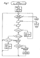
- the drawing shows exemplary embodiments both for the method according to the invention and for the device. They are described in more detail below.
- a vehicle speed threshold "SchW” ⁇ e.g.
- the windshield wiper drive motor is switched to the speed level that corresponds to the numerical value of ASW specified (or automatically set) by ASW [output of ASW to an output stage "ES"].
- the driving speed v is now compared with the threshold value SchW. [ v> Schw ]: If your current value is greater than the threshold value, the process branches to the right. Any exceeding of the threshold value is saved by setting the memory V SP - here to the value 1. This is necessary because the automatic changeover of the drive motor should only take effect if the vehicle speed threshold value is run through from above. For the same reason, AUTO is always set to 0 (reset) in this branch. In addition, ASW is reset to the value of MSW in each run of this branch before returning to the switch query.
- the automatic switchover can also be carried out in such a way that all speed levels are switched back to a single lower level, which would then preferably be a slow interval level.
- FIG. 2 shows a schematic circuit example of a device which is suitable for performing the method according to the invention.
- a wiper - control switch 1 connected to positive potential via an ignition switch Zü has, in addition to its switch-off position 0, the three usual operating positions with fixed contacts I for an interval, II for a slow and III for a fast wiper speed level.
- the control switch 1 or its fixed contacts I to III are connected to an electronic control unit 2, which a Network 2.1 from logical gates and other components - the function of which will be described in detail later - and has an output stage 2.2. It activates an electric drive motor 3 for one or more windshield wipers (not shown) in different speed levels for continuous or interval operation in accordance with the operating positions of the control switch 1 or the logical signal links in the network 2.1.
- a threshold switch 4 is also connected to the control unit 3 for the transfer of threshold switching signals.
- the threshold switch 4 which is also supplied with voltage via the ignition switch Zü, receives a signal proportional to the vehicle speed of a vehicle speed sensor v, z. B. an electronic tachometer supplied.
- the threshold switch 4 At a defined threshold of the vehicle speed - indicated by SchW - the z. B. is about 40 km / h, the threshold switch 4 - a negative switching edge when going upwards, - a positive switching edge when traversing downwards, a certain hysteresis HYST between upward and downward passes is of course provided.
- the network 2.1 contains a current path to the output stage 2.2 for each of the fixed contacts I, II and III.
- the fixed contact I is connected directly to an input of two AND gates G1 and G2.
- Fixed contact II is connected directly to an input of two AND gates G3 and G4.
- Fixed contact III is connected directly to an input of two AND gates G5 and G6.
- the outputs of the AND gates G1 and G4 as well as G3 and G6 are linked via an OR gate OG1 and OG2.
- the outputs of the gates G2, OG1, OG2 and G5 are each connected to a driver stage and are connected in each case via resistors R to the bases of transistors T1, T2, T3 and T4, the collectors of which are each connected via a resistor R to plus potential and whose emitter is connected to ground.
- Connections to the output stage 2.2 are provided on the collectors of the transistors T1, T2 and T3 at nodes A, B and C, respectively.
- the respective electrical potential of the same nodes A, B and C which is dependent on the switching state of the transistors T1 to T3, is in each case connected to the second inputs of the AND gates G1, G3 and G5.
- Outputs of AND gates G7, G8 and G9 are connected to the second inputs of the AND gates G2, G4 and G6, respectively.
- Their first inputs are connected to the output of the threshold switch 4, while their respective second inputs via a signal-delaying RC element 6 to the output 5A of a z. B. connected as a flip-flop (FF) memory circuit 5 are connected.
- the RC element 6 has an adjustable discharge resistance 6.1.
- the memory circuit 5 has a static RESET input 5R. This is controlled by an output INV of the output of the threshold switch 4.
- the vehicle user should now manually switch the control switch 1 into an operating position, the driving speed of the motor vehicle being greater than the threshold value.
- the plus potential present at its switch contact is thus placed on one of the fixed contacts I, II or III.
- the OR gate OG3 turns on and applies positive potential to an input of the AND gate G10. Since both inputs of the AND gate G1 are now at plus potential - from the node A and from the fixed contact I - the transistor T2 switches through and the output stage 2.2 activates the drive motor 3 for interval operation. In the same way, the slow and fast continuous speed stage of the drive motor 3 can be switched on via the fixed contacts II and III.
- the transistor T2 or T3 assigned to the next lower speed stage is activated by switching the AND gates G1, G3 or G5 and the one assigned to the speed stage to be switched on - T3 or T4 - is activated. If the driving speed is now lowered below the threshold value during wiper operation, the output of the threshold value switch 4 switches from ground to plus potential.
- the memory circuit 5 remains in the RESET state for the reasons mentioned above; ie, the plus signal from the output 5A of the memory circuit 5, which was previously located at an input of the AND gates G7, G8 and G9, is now accompanied by the output signal of the threshold switch 4, also with plus potential, so that the AND gates G7, G8 and G9 can now be switched through.
- the AND gates G2, G4 or G6 is also turned on one input of which already has positive potential from one of the fixed contacts of the control switch 1.
- the fixed contact I is selected for interval operation, so that the AND gate G2 can now switch through.
- the transistor T1 is then turned on and the plus potential at node A disappears.
- the AND gate G1 blocks, the transistor T2 likewise, and the drive motor 3 is automatically switched over to the next lower speed level, in this case to standstill.
- the threshold switch 4 When running through the driving speed - threshold value from below, the threshold switch 4 switches its output back from plus potential to ground. This immediately blocks the AND gate G10 and connects the input of the inverter INV to ground. With the consequent blocking of the AND gates G7, G8 and G9, the operating state of the drive motor 3 which was switched on before the running speed - threshold value at the control switch 1 is restored - blocking G2 and T1, G1, OG1 and T2 switch through and the drive motor 3 goes into interval operation. The memory circuit 5 is switched back to its static RESET state.
- the input of the AND gate G10 connected to the non-overlapping fixed contacts I, II and III becomes briefly potential-free while the switching contact of the control switch 1 is switched over; the AND gate G10 blocks and generates a positive switching edge at the dynamic SET input of the memory circuit 5 when switching through again - which occurs when the control switch 1 is moved to another operating position or to the same operating position as before - because, however, ground is now at the RESET Input of the memory circuit 5 is present - the inverter input already has positive potential from the threshold switch 4 - the memory circuit 5 is set to the SET state.
- the RC element 6 causes the AND gate G10 to remain switched through until the memory circuit 5 has switched safely.
Landscapes
- Engineering & Computer Science (AREA)
- Automation & Control Theory (AREA)
- Mechanical Engineering (AREA)
- Control Of Electric Motors In General (AREA)
- Control Of Direct Current Motors (AREA)
Applications Claiming Priority (2)
| Application Number | Priority Date | Filing Date | Title |
|---|---|---|---|
| DE3916549 | 1989-05-20 | ||
| DE3916549A DE3916549C1 (fr) | 1989-05-20 | 1989-05-20 |
Publications (3)
| Publication Number | Publication Date |
|---|---|
| EP0399217A2 true EP0399217A2 (fr) | 1990-11-28 |
| EP0399217A3 EP0399217A3 (fr) | 1992-12-02 |
| EP0399217B1 EP0399217B1 (fr) | 1995-06-21 |
Family
ID=6381112
Family Applications (1)
| Application Number | Title | Priority Date | Filing Date |
|---|---|---|---|
| EP90107596A Expired - Lifetime EP0399217B1 (fr) | 1989-05-20 | 1990-04-21 | Procédé pour commander un moteur d'entraînement d'une installation d'essuie-glace de véhicule automobile |
Country Status (5)
| Country | Link |
|---|---|
| US (1) | US5153488A (fr) |
| EP (1) | EP0399217B1 (fr) |
| JP (1) | JPH0310950A (fr) |
| DE (1) | DE3916549C1 (fr) |
| ES (1) | ES2075085T3 (fr) |
Cited By (2)
| Publication number | Priority date | Publication date | Assignee | Title |
|---|---|---|---|---|
| EP0504606A1 (fr) * | 1991-03-21 | 1992-09-23 | MAN Nutzfahrzeuge Aktiengesellschaft | Dispositif de commande du moteur d'essuie-glace d'un véhicule automobile |
| GB2306701A (en) * | 1995-10-21 | 1997-05-07 | Ford Motor Co | Vehicle rear wiper arrangement |
Families Citing this family (3)
| Publication number | Priority date | Publication date | Assignee | Title |
|---|---|---|---|---|
| IT1284333B1 (it) * | 1996-01-23 | 1998-05-18 | Fiat Auto Spa | Metodo e unita' di regolazione della frequenza di battuta di un tergicristallo. |
| DE10118173B4 (de) * | 2001-04-11 | 2014-02-13 | Volkswagen Ag | Wischersteuerung |
| CN108124437B (zh) * | 2017-09-27 | 2023-03-21 | 株式会社小松制作所 | 作业车辆的集成开关装置及具有集合开关装置的作业车辆 |
Family Cites Families (20)
| Publication number | Priority date | Publication date | Assignee | Title |
|---|---|---|---|---|
| DE1530979A1 (de) * | 1967-02-09 | 1970-09-24 | Bosch Gmbh Robert | Verfahren fuer einen Impulsgeber fuer die Scheibenwischerbetaetigung in Kraftfahrzeugen |
| DE2403311A1 (de) * | 1974-01-24 | 1975-07-31 | Herbert Handte | Neuartig programmierbares steuergeraet fuer den kontinuierlichen und/oder intermittierenden betrieb insbesondere von scheibenwischern |
| DE2503767C2 (de) * | 1975-01-30 | 1976-12-02 | Helmut Stephan | Vorrichtung zur steuerung des antriebsmotors einer scheibenwischeranlage |
| DE2508947C3 (de) * | 1975-03-01 | 1982-02-25 | Merck Patent Gmbh, 6100 Darmstadt | Verfahren zur Herstellung von 4-Oxo-1,2,3,6,7, 11b-hexahydro-4H-pyrazino [2,1-a] isochinolinen |
| JPS5621932A (en) * | 1979-07-27 | 1981-02-28 | Hitachi Ltd | Wiper controller |
| GB2048590B (en) * | 1979-04-04 | 1984-01-25 | Hitachi Ltd | Apparatus and method for controlling automobile equipment |
| JPS55156737A (en) * | 1979-05-25 | 1980-12-06 | Hitachi Ltd | Wiper control device for automobile |
| JPS55164539A (en) * | 1979-06-08 | 1980-12-22 | Fujitsu Ten Ltd | Intermittent wiper circuit |
| JPS5660749A (en) * | 1979-10-18 | 1981-05-25 | Nec Corp | Speed responsive windshield wiper |
| JPS56120436A (en) * | 1980-02-27 | 1981-09-21 | Nissan Motor Co Ltd | Windshield wiper |
| DE3021877A1 (de) * | 1980-06-11 | 1981-12-24 | Bayerische Motoren Werke AG, 8000 München | Schaltanordnung fuer den intervallbetrieb eines scheibenwischermotors von kraftfahrzeugen |
| US4625157A (en) * | 1981-06-25 | 1986-11-25 | Phillimore Horace R | Windshield wiper control |
| FR2515588A1 (fr) * | 1981-10-30 | 1983-05-06 | Raes Marc | Temporisateur d'essuie-glace a reglage automatique selon la vitesse |
| JPS59149843A (ja) * | 1983-02-14 | 1984-08-27 | Nippon Radiator Co Ltd | 自動車用オ−トワイパ |
| JPS60140401A (ja) * | 1983-12-27 | 1985-07-25 | Nippon Denso Co Ltd | 車両用制御装置 |
| JPS60166548A (ja) * | 1984-02-10 | 1985-08-29 | Toyota Motor Corp | 車両ワイパの速度制御方法 |
| JPS6160352A (ja) * | 1984-08-31 | 1986-03-28 | Toyota Motor Corp | 車両用ワイパ制御装置 |
| JPS6226148A (ja) * | 1985-07-25 | 1987-02-04 | Fujitsu Ten Ltd | ワイパ駆動装置 |
| DE3527406A1 (de) * | 1985-07-31 | 1987-02-12 | Bosch Gmbh Robert | Wischintervall-steuervorrichtung |
| JPS62295755A (ja) * | 1986-06-14 | 1987-12-23 | Toshio Azuma | 間欠ワイパ− |
-
1989
- 1989-05-20 DE DE3916549A patent/DE3916549C1/de not_active Expired - Lifetime
-
1990
- 1990-04-21 EP EP90107596A patent/EP0399217B1/fr not_active Expired - Lifetime
- 1990-04-21 ES ES90107596T patent/ES2075085T3/es not_active Expired - Lifetime
- 1990-05-21 US US07/525,680 patent/US5153488A/en not_active Expired - Fee Related
- 1990-05-21 JP JP2131123A patent/JPH0310950A/ja active Pending
Cited By (2)
| Publication number | Priority date | Publication date | Assignee | Title |
|---|---|---|---|---|
| EP0504606A1 (fr) * | 1991-03-21 | 1992-09-23 | MAN Nutzfahrzeuge Aktiengesellschaft | Dispositif de commande du moteur d'essuie-glace d'un véhicule automobile |
| GB2306701A (en) * | 1995-10-21 | 1997-05-07 | Ford Motor Co | Vehicle rear wiper arrangement |
Also Published As
| Publication number | Publication date |
|---|---|
| DE3916549C1 (fr) | 1990-05-17 |
| EP0399217A3 (fr) | 1992-12-02 |
| JPH0310950A (ja) | 1991-01-18 |
| US5153488A (en) | 1992-10-06 |
| EP0399217B1 (fr) | 1995-06-21 |
| ES2075085T3 (es) | 1995-10-01 |
Similar Documents
| Publication | Publication Date | Title |
|---|---|---|
| DE69305023T2 (de) | Scheibenwischergeschwindigkeits- und -intervallregelung | |
| DE19756504B4 (de) | Steuereinrichtung für eine Scheibenwischereinrichtung | |
| EP0431245B1 (fr) | Installation de commande d'un essuie-glace | |
| DE2926938A1 (de) | Schaltanordnung zum antrieb eines beweglichen elementes, insbesondere zum antrieb von scheiben o.dgl. in kraftfahrzeugen | |
| EP0407538A1 (fr) | Dispositif de commande des organes d'entrainement d'accessoires de vehicules. | |
| DE3123452A1 (de) | Mechanische anordnung fuer eine betaetigungsvorrichtung | |
| DE3926178A1 (de) | Aufweck-schaltungsanordnung fuer einen mikroprozessor | |
| DE3440525C2 (fr) | ||
| DE19756502C2 (de) | Steuereinrichtung für eine Scheibenwischereinrichtung | |
| EP0283005B2 (fr) | Méthode et interrupteur d'intervalle avec agencement de circuit pour commander le retard de balayage des essuie-glaces de véhicules | |
| DE3615531C2 (fr) | ||
| DE3114836A1 (de) | Steuersystem fuer eine brennkraftmaschine | |
| DE3042130A1 (de) | Automatische kimaanlage | |
| DE4237243A1 (fr) | ||
| DE3539683C2 (fr) | ||
| DE2618028C2 (de) | Universell einsetzbares, in integrierter Schaltkreistechnik ausführbares Zeitglied | |
| EP0399217B1 (fr) | Procédé pour commander un moteur d'entraînement d'une installation d'essuie-glace de véhicule automobile | |
| DE19611840A1 (de) | System zur Bestimmung der Übersetzungsänderungen bei einem Automatikgetriebe | |
| DE2013413A1 (fr) | ||
| DE3930732A1 (de) | Anlage zum waschen von windschutzscheiben | |
| DE4205268C1 (en) | Windscreen wipers for vehicle - have control system setting initial wiping speed and intervals between wipes | |
| DE69009262T2 (de) | Elektronischer Schaltkreis zur Messung und Regelung eines durch eine induktive elektrische Last fliessenden Stromes. | |
| DE69513786T2 (de) | Durch Scheibenwischer automatisch gesteuerte Fahrzeugscheinwerfer | |
| DE69005563T2 (de) | Systemstruktur zur automatischen Steuerung einer Fahrzeuggeschwindigkeit auf die gewünschte Reisegeschwindigkeit. | |
| DE2954670C2 (en) | Electrically powered vehicle window drive |
Legal Events
| Date | Code | Title | Description |
|---|---|---|---|
| PUAI | Public reference made under article 153(3) epc to a published international application that has entered the european phase |
Free format text: ORIGINAL CODE: 0009012 |
|
| AK | Designated contracting states |
Kind code of ref document: A2 Designated state(s): ES FR GB IT SE |
|
| PUAL | Search report despatched |
Free format text: ORIGINAL CODE: 0009013 |
|
| AK | Designated contracting states |
Kind code of ref document: A3 Designated state(s): ES FR GB IT SE |
|
| 17P | Request for examination filed |
Effective date: 19921023 |
|
| 17Q | First examination report despatched |
Effective date: 19940405 |
|
| GRAA | (expected) grant |
Free format text: ORIGINAL CODE: 0009210 |
|
| ITF | It: translation for a ep patent filed | ||
| AK | Designated contracting states |
Kind code of ref document: B1 Designated state(s): ES FR GB IT SE |
|
| GBT | Gb: translation of ep patent filed (gb section 77(6)(a)/1977) |
Effective date: 19950719 |
|
| ET | Fr: translation filed | ||
| REG | Reference to a national code |
Ref country code: ES Ref legal event code: FG2A Ref document number: 2075085 Country of ref document: ES Kind code of ref document: T3 |
|
| PLBE | No opposition filed within time limit |
Free format text: ORIGINAL CODE: 0009261 |
|
| STAA | Information on the status of an ep patent application or granted ep patent |
Free format text: STATUS: NO OPPOSITION FILED WITHIN TIME LIMIT |
|
| 26N | No opposition filed | ||
| REG | Reference to a national code |
Ref country code: GB Ref legal event code: 732E |
|
| PGFP | Annual fee paid to national office [announced via postgrant information from national office to epo] |
Ref country code: GB Payment date: 20000410 Year of fee payment: 11 |
|
| PGFP | Annual fee paid to national office [announced via postgrant information from national office to epo] |
Ref country code: FR Payment date: 20000420 Year of fee payment: 11 |
|
| PGFP | Annual fee paid to national office [announced via postgrant information from national office to epo] |
Ref country code: SE Payment date: 20000426 Year of fee payment: 11 Ref country code: ES Payment date: 20000426 Year of fee payment: 11 |
|
| PG25 | Lapsed in a contracting state [announced via postgrant information from national office to epo] |
Ref country code: GB Free format text: LAPSE BECAUSE OF NON-PAYMENT OF DUE FEES Effective date: 20010421 |
|
| PG25 | Lapsed in a contracting state [announced via postgrant information from national office to epo] |
Ref country code: SE Free format text: LAPSE BECAUSE OF NON-PAYMENT OF DUE FEES Effective date: 20010422 |
|
| PG25 | Lapsed in a contracting state [announced via postgrant information from national office to epo] |
Ref country code: ES Free format text: LAPSE BECAUSE OF NON-PAYMENT OF DUE FEES Effective date: 20010423 |
|
| PG25 | Lapsed in a contracting state [announced via postgrant information from national office to epo] |
Ref country code: FR Free format text: THE PATENT HAS BEEN ANNULLED BY A DECISION OF A NATIONAL AUTHORITY Effective date: 20010430 |
|
| EUG | Se: european patent has lapsed |
Ref document number: 90107596.0 |
|
| GBPC | Gb: european patent ceased through non-payment of renewal fee |
Effective date: 20010421 |
|
| REG | Reference to a national code |
Ref country code: FR Ref legal event code: ST |
|
| REG | Reference to a national code |
Ref country code: ES Ref legal event code: FD2A Effective date: 20030203 |
|
| PG25 | Lapsed in a contracting state [announced via postgrant information from national office to epo] |
Ref country code: IT Free format text: LAPSE BECAUSE OF NON-PAYMENT OF DUE FEES Effective date: 20050421 |