EP0504643A2 - Procédé et installation pour le refroidissement et/ou chauffage d'une cabine - Google Patents
Procédé et installation pour le refroidissement et/ou chauffage d'une cabine Download PDFInfo
- Publication number
- EP0504643A2 EP0504643A2 EP92103510A EP92103510A EP0504643A2 EP 0504643 A2 EP0504643 A2 EP 0504643A2 EP 92103510 A EP92103510 A EP 92103510A EP 92103510 A EP92103510 A EP 92103510A EP 0504643 A2 EP0504643 A2 EP 0504643A2
- Authority
- EP
- European Patent Office
- Prior art keywords
- air
- duct
- air flow
- control element
- cooling
- Prior art date
- Legal status (The legal status is an assumption and is not a legal conclusion. Google has not performed a legal analysis and makes no representation as to the accuracy of the status listed.)
- Granted
Links
Images


Classifications
-
- B—PERFORMING OPERATIONS; TRANSPORTING
- B60—VEHICLES IN GENERAL
- B60H—ARRANGEMENTS OF HEATING, COOLING, VENTILATING OR OTHER AIR-TREATING DEVICES SPECIALLY ADAPTED FOR PASSENGER OR GOODS SPACES OF VEHICLES
- B60H1/00—Heating, cooling or ventilating devices
- B60H1/32—Cooling devices
- B60H1/3202—Cooling devices using evaporation, i.e. not including a compressor, e.g. involving fuel or water evaporation
-
- B—PERFORMING OPERATIONS; TRANSPORTING
- B60—VEHICLES IN GENERAL
- B60H—ARRANGEMENTS OF HEATING, COOLING, VENTILATING OR OTHER AIR-TREATING DEVICES SPECIALLY ADAPTED FOR PASSENGER OR GOODS SPACES OF VEHICLES
- B60H1/00—Heating, cooling or ventilating devices
- B60H1/00007—Combined heating, ventilating, or cooling devices
-
- B—PERFORMING OPERATIONS; TRANSPORTING
- B60—VEHICLES IN GENERAL
- B60H—ARRANGEMENTS OF HEATING, COOLING, VENTILATING OR OTHER AIR-TREATING DEVICES SPECIALLY ADAPTED FOR PASSENGER OR GOODS SPACES OF VEHICLES
- B60H1/00—Heating, cooling or ventilating devices
- B60H1/00357—Air-conditioning arrangements specially adapted for particular vehicles
- B60H1/00385—Air-conditioning arrangements specially adapted for particular vehicles for vehicles having an electrical drive, e.g. hybrid or fuel cell
-
- B—PERFORMING OPERATIONS; TRANSPORTING
- B60—VEHICLES IN GENERAL
- B60H—ARRANGEMENTS OF HEATING, COOLING, VENTILATING OR OTHER AIR-TREATING DEVICES SPECIALLY ADAPTED FOR PASSENGER OR GOODS SPACES OF VEHICLES
- B60H1/00—Heating, cooling or ventilating devices
- B60H1/32—Cooling devices
- B60H1/3201—Cooling devices using absorption or adsorption
-
- B—PERFORMING OPERATIONS; TRANSPORTING
- B60—VEHICLES IN GENERAL
- B60H—ARRANGEMENTS OF HEATING, COOLING, VENTILATING OR OTHER AIR-TREATING DEVICES SPECIALLY ADAPTED FOR PASSENGER OR GOODS SPACES OF VEHICLES
- B60H1/00—Heating, cooling or ventilating devices
- B60H1/32—Cooling devices
- B60H1/3201—Cooling devices using absorption or adsorption
- B60H1/32014—Cooling devices using absorption or adsorption using adsorption, e.g. using Zeolite and water
Definitions
- the invention relates to a device for heating and / or cooling a cabin, in particular a passenger compartment in a motor vehicle, according to the preamble of claim 1 and a method for cooling and / or heating with such a device.
- cooling channels for a liquid coolant are known, through which all components with heat generation flow, in order to remove the thermal energy from them. Since the temperature profile is subject to very strong fluctuations and, at least for a short time, larger amounts of heat are to be dissipated, a heat exchanger arranged in the coolant flow must be designed for this most unfavorable maximum operating point with regard to its heat transfer capacity.
- cooling of the passenger compartment at high outside temperatures and possibly high relative air humidity is also desirable, with the energy expenditure for cooling being as low as possible and environmentally friendly substances being used as coolants.
- the invention has for its object to provide a device for heating and / or cooling a cabin, in particular a passenger compartment in a vehicle without or with the internal combustion engine not in operation, with which heating or cooling is possible with low energy consumption and using environmentally friendly substances .
- Such a device with a sorption reactor requires little auxiliary energy during the heating or cooling of a passenger compartment.
- Zeolite is an environmentally compatible sorbent and enables simple, maintenance-friendly construction of a heating and / or cooling device.
- the cabin air is drawn off via the exhaust air duct, preferably via an air / air heat exchanger and the inflow duct of the reaction chamber fed.
- the dehumidified air emerging from the outflow channel of the reaction chamber is cooled in a first air / air heat exchanger with ambient air and in a second air / air heat exchanger with cabin exhaust air, is further cooled adiabatically in an evaporator by evaporation of water to the cooling limit and can then be introduced directly into the cabin via the supply air duct.
- a moist air stream is supplied via the inflow channel to the reaction chamber, which is dehumidified by adsorption in the sorption reactor and thereby absorbs heat
- the dry hot air stream emerging from the outflow channel receiving its heat energy in an air / air heat exchanger emits a cooling air flow which is supplied to the cabin as a heating air flow.
- the cooling air flow can be composed of freely selectable proportions of fresh air and circulating air.
- the exhaust air from the cabin flows through an evaporator, from which the moist air flows through a further heat exchanger to the sorption reactor.
- the supply air duct is connected to the exhaust air duct via an air duct and at least one fan is arranged in the air duct to produce an appropriate air flow.
- a cooler which is located in a cooling circuit of the drive components and is acted upon by its coolant, is provided as the heat source, the fan and the cooler being arranged one behind the other in the air duct.
- a first air flow control element is also installed in front of the cooler, which controls the proportion of circulating air and exhaust air.
- a second air flow control element controls the proportion of heating air introduced into the passenger compartment and cooling air discharged to the surroundings.
- the sorption reactor is arranged after the second air flow control element.
- auxiliary units with heat generation can be connected to the cooling circuit, a coolant pump being provided for the circulation of the coolant and being driven by an electric motor.
- a coolant pump being provided for the circulation of the coolant and being driven by an electric motor.
- the coolant is fed to it at a relatively constant temperature level.
- a heat accumulator is provided before the coolant enters the cooler, which compensates for the extreme fluctuations in the heat development in the individual components.
- a latent heat accumulator is particularly suitable at this point, by means of which it is possible to immediately provide heat energy for heating the passenger compartment again after a brief interruption in the journey.
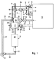
- the device for heating and / or cooling a cabin 10, in particular the passenger compartment of a motor vehicle, shown schematically in FIGS. 1 to 4, has a sorption reactor 20 with a sorbent, such as zeolite or the like, as an energy store (heat source) and air channels, through which air flows are guided according to the operating state by means of air flow control elements.
- a sorption reactor 20 with a sorbent such as zeolite or the like, as an energy store (heat source) and air channels, through which air flows are guided according to the operating state by means of air flow control elements.
- the reaction chamber 21 of the sorption reactor 20 is supplied with a cabin air flow via an inflow channel 22, which in cooling mode via an exhaust air channel 11 and in heating mode via an evaporator 13, the supply air channel 12, the air flow control element 54, the air duct 7 and the lust flow control element 53 is suctioned off.
- the exhaust air duct 11 is connected to the inflow duct 22 via an air flow control element 51, which in position 1 establishes a flow connection between the inflow duct and the exhaust air duct and closes the exhaust air duct 11 in a position 2 and connects the inflow duct 22 to a fresh air duct 8.
- the outflow duct 23 of the reaction chamber 21 carrying a dry warm air flow is connected in cooling operation via an air flow control element 50 to an inlet air duct 12 of the cabin 10.
- an air flow control element 50 to an inlet air duct 12 of the cabin 10.
- position 1 the hot air flow from the outflow duct 23 enters the supply air duct 12, while in position 2 of the air flow control element 50 the supply air duct 12 is closed and the outflow duct 23 opens into an exhaust air duct 9.
- An evaporator 13 is arranged in the supply air duct 12, preferably directly adjacent to the cabin 10. Suitable surfaces 17 for evaporation are supplied from a water reservoir 15 by means of a pump 16 via a valve 14 to a water 14.
- the outflow channel 23 and the inflow channel 22 are in heat-transferring connection.
- a heat exchanger 24, preferably a cross-flow heat exchanger, is arranged.
- a further evaporator 25 with suitable surfaces 26 is advantageously arranged in the inflow channel 22.
- a heat-dissipating heat exchanger 27 is arranged between the sorption reactor 20 and the cross-flow heat exchanger 24 and can form a structural unit with the heat exchanger 24.
- the heat exchanger 27 is from a cooling air flow 28 flows through, which is generated by a cooling fan 29.
- the cooling air flow emerging from the heat exchanger 27 is discharged into the atmosphere via a cooling air duct 30 and an exhaust air duct 31.
- cabin air is drawn off via the exhaust air duct 11, which flows through the heat exchanger 24 as an exhaust air flow and is heated.
- the exhaust air flow enters the sorption reactor 20 via the inflow channel 22.
- the sorbent in the exemplary embodiment shown zeolite, adsorbs the moisture, generating heat of adsorption which leads to the heating of the air flowing through.
- the air emerging from the outflow channel 23 is thus a dry warm air flow which is cooled in the heat exchanger 27 by the cooling air flow 28 and in the heat exchanger 24 releases the residual heat for heating the exhaust air drawn off from the cabin.
- the cooled, dried air flows into the supply air duct 12 and the evaporator 13 via the control element 50, where it is cooled adiabatically with evaporation of water up to the cooling limit.
- the cooled air preferably exits the evaporator directly into the cabin.
- the cabin can be cooled by drying in the sorption reactor, pre-cooling in the heat exchangers and adiabatic re-humidification of the air.
- the air flow from the cabin to the sorption reactor 20 and back to the cabin is maintained by means of a blower 19 which is arranged in the inflow channel 22.
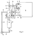
- a heating device 18 is arranged in the inflow channel 22 before entry into the reaction chamber 21, the operation of which is described below.
- a bridge duct 7 connects the inflow duct 22 to the supply air duct 12 via air flow control elements 53 and 54.
- the cooling air duct 30 is designed to open into the cabin 10, the exhaust air duct 31 being connected via an air flow control element 52.
- the air flow control elements 50, 52, 53 and 54 are switched to position 2 so that their flaps open the bridge channel 7 and the cooling air channel 30, respectively, for heating the cabin 10.
- warm exhaust air is drawn in from the cabin 10 via the supply air duct 12, which preferably absorbs water in the evaporator 13 until saturation.
- the exhaust air enters the inflow duct 22 via the bridge duct 7 and the control element 53 and, as described in FIG. 1, flows through the reaction chamber 21 of the sorption reactor 20.
- the hot air exiting via the outflow duct 23 gives it Heat in the heat exchanger 27 to the cooling air flow 28, which is generated by the cooling fan 29.
- the cooling air flow is composed of fresh air and circulating air, the circulating air being sucked out of the cabin by means of blowers 29 via the air flow control element 60 and the air duct 32.
- the cooling air flow 28 enters the cabin 10 as heating air via the cooling air duct 30.
- the cooled air exits into the atmosphere via the exhaust air duct 9.
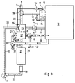
- the device can also be used for heating as shown in FIG. 3.
- Fresh air is supplied to the inflow duct 22 via the fresh air duct 8 and the air flow control element 51 in position 2.
- This fresh air is heated in the cross-flow heat exchanger 24 and humidified via the evaporator 25 until saturation.
- the heated, humidified fresh air flows into the reaction chamber 21 of the sorption reactor 20 and exits as a dry warm air flow through the outflow duct 23, which is connected to the exhaust air duct 9 via the air flow control element 50 in position 2.
- the heat of adsorption discharged from the sorption reactor 20 is released to the cooling air flow 28, which enters the cabin 10 as heating air via the cooling air duct 30.
- the cooling fan 29 draws in cabin air via a circulating air duct 32, fresh air being simultaneously sucked in from a fresh air duct 33 via a control element 60. Depending on the operating conditions, a corresponding proportion of fresh air can be supplied to the sucked-in cabin air, this mixed air stream flowing through the heat exchanger 27 as cooling air stream and entering the cabin 10 as heating air.
- the bridge channel 7 shown in dashed lines in FIGS. 1 and 2 can be omitted.
- the sorption reactor If the sorption reactor has absorbed a certain amount of water, it must be desorbed for regeneration.
- fresh air is supplied to the inflow channel 22 via the fresh air channel 8 and is heated up in the heating device 18 before entering the reaction chamber 21.
- An electrical heating register can be used as the heating device 18 are used, which is in operation for example when charging the batteries of an electric vehicle; in a vehicle with an internal combustion engine, the necessary thermal energy can be extracted from the exhaust gas via a heat exchanger.
- the heated fresh air absorbs water from the sorbent and discharges it via the outflow duct 23 and the heat exchanger 24 and the exhaust air duct 9.
- the moist, warm air from the sorption reactor gives off heat to the fresh air, as a result of which part of the waste heat is recovered.
- the end of the desorption process can be determined on the basis of an increase in the temperature in the outflow channel 23.
- the temperature rise at the end of the desorption process can advantageously be used to heat the cabin 10, for which purpose the cooling fan 29 has to be switched on and the cooling air flow can be supplied to the cabin as heating air via the cooling air duct 30.
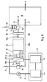
- the embodiment of the device according to the invention shown in FIG. 5 is used exclusively for heating a cabin 10, e.g. of the passenger compartment of an electric vehicle.
- a cabin 10 e.g. of the passenger compartment of an electric vehicle.
- exhaust air is sucked in via the exhaust air duct 11 and fresh air is drawn in via the duct 36 and blown into the cabin 10 via the supply air duct 12.
- An exhaust air portion corresponding to the fresh air portion is released to the environment via the exhaust air connector 37.
- a blower 6 arranged in the supply air duct 12 ensures sufficient air circulation.
- a heat exchanger 27 preferably a cross-flow heat exchanger, is arranged in the supply air duct 12, through which the dry warm air is led and which releases the absorbed heat of absorption to the circulating air flow.
- the inflow duct 22 to the reaction chamber 21 of the sorption reactor 20 is connected to the outflow duct 23 via a circulating air duct 38.
- the air circulation in the closed circuit thus formed is maintained by the fan 19.
- the dry circulating air of the sorption reactor, cooled by the heat given off in the heat exchanger 27, is humidified to the saturation limit in the evaporator 25 before re-entering the reaction chamber 21.
- the evaporator has a water circuit operated by a pump 25a, which permanently applies water from a water reservoir 25b to suitable surfaces 26 for evaporation.
- a heat exchanger 40 of a cooling circuit 41 is advantageously integrated in the evaporator 25 and removes any waste heat that may be present from any units.
- the heat-absorbing side of the cooling circuit operated by the pump 43 is stylized by a circle 42.
- the outflow duct 23 can optionally be connected to the exhaust air duct 9 or the recirculated air duct 38 via the air flow control element 50, while the fresh air duct 8 or the recirculated air duct 38 can optionally be connected to the inflow duct 22 via the airflow control element 51 integrated in the fan.
- the blower 19 draws in fresh air via the fresh air duct 8, which can be blown off via an exhaust air duct 31, via the air flow control element located in position 1 52 branches off between the evaporator 25 and the sorption reactor 20.
- the heat-storing sorption reactor 20 has to be desorbed, this can be done - as described in relation to FIG. 4 - by opening the fresh air duct and the exhaust air duct with the addition of thermal energy. It is preferably provided to arrange a bypass duct 39 which bypasses the fan 19 and which connects to the said ducts via air flow control elements 55 and 56 between the inflow duct 22 and the circulating air duct 38.
- an adequate heating of the passenger compartment is also possible in the case of an electric vehicle, a hybrid vehicle or another vehicle without an internal combustion engine, as well as in the case of stationary air conditioning.
- the small amounts of heat to be dissipated in a vehicle without an internal combustion engine can advantageously be used to enrich the reaction air supplied to the sorption reactor 20 with water.
- the device shown in FIG. 6 is used in particular for heating the cabin 10 or a passenger compartment of an electric vehicle.
- An inlet air duct 12 and an exhaust air duct 11 are connected to the cabin 10.
- the exhaust air duct 11 is connected to the supply air duct 12 via an air duct 90; the air duct 90 essentially has three sections 90a, 90b, 90c.
- the first section 90a of the air duct 90 extends from the exhaust duct 11 to a first airflow control element 51.
- the second section 90b of the air duct 90 begins at the first airflow control element 51 and extends to a second airflow control element 52, in which second section 90b a fan 19 and a cooler 40 for cooling the electric drive unit 44 are arranged.
- the third section 90c of the air guide duct 90 extends from the second air flow control element 52 to the supply air duct 12 on the passenger compartment 10.
- a humidifier 25 In the third section 90c of the air guide duct 90 there are a humidifier 25, a sorption reactor 20 and a zeolite store in series an additional electrical heater 81 is arranged. Without heat recovery from the exhaust air, a high proportion of recirculated air is required for energy reasons. The evaporation of moisture from the cabin occupants increases the relative humidity in the passenger compartment with a high proportion of recirculated air. A drying device is therefore necessary to achieve a high proportion of circulating air. In the sorption reactor 20, the water of the air stream is adsorbed by the zeolite contained therein, whereby it is dried.
- the heat released in the process further heats the air flow.
- the sorption reactor 20 thus also serves as a heat store. If the air flow is too low, this is increased in the humidifier 25 in order to then be able to release heat from the sorbent, advantageously zeolites, to a greater extent.
- a fresh air duct 36 carrying cold air opens into the air mixing chamber 82, the proportion of cold or fresh air being admixed to the air flow carried in section 90c.
- a blower 6 is provided in the fresh air duct 36 to provide the required amount of fresh air or cold air.
- An evaporative cooler 13 is arranged in the fresh air duct 36 for cooling the fresh air.
- the cooler 40 through which the air flow flows in the second section 90b of the air duct 90 is acted upon on the other side of the heat exchange walls by the coolant of a cooling circuit 41 for the drive unit 44 of the electric vehicle.
- the coolant of the cooling circuit 41 not only serves to cool the drive motor itself, but drive is to be understood here as the overall arrangement of the motor, transmission, power control and battery unit.
- a coolant pump 43 for moving the coolant is located in the cooling circuit 41. Due to fluctuations in the development of heat in the components of the drive 44, a buffering heat accumulator 45 is provided, which is preferably designed as a latent heat accumulator. The temperature fluctuations are dampened by the heat accumulator 45, as a result of which the heat supplied to the cooler 40 remains at a level which is kept relatively constant within certain limits.
- the heating mode for the passenger compartment is dependent on several influences, but primarily on the ambient temperatures, the sunshine and the interior temperature in the passenger compartment. Therefore, the "heating" function and the amount of heat required must be set as required, whereas the cooling of the drive when the electric vehicle is in operation is always required, even if the cooling power requirement is subject to certain fluctuations, which are determined, for example, by climatic conditions or by the power profile.
- the drive is cooled in that the coolant flows through corresponding cooling channels of the engine, the transmission, the battery (possibly with an intermediate heat transfer circuit) and the power control, the coolant in the cooling circuit 41 being moved with the aid of the coolant pump 43.
- the heat generation and the amount of heat to be dissipated are subject to extreme fluctuations, in particular in the case of load changes such as when accelerating, braking, etc. So that the cooler 40 does not have to be made unnecessarily large in terms of its dimensions, the heat accumulator 45 has the function of a thermal buffer which is capable of doing so to absorb the quantities of heat that often occur only briefly and to supply the coolant to the cooler 40 at a relatively constant temperature level. The heat contained in the coolant is released in the cooler 40 to the air flowing through the second section 90 b of the air duct 90.
- the air flow required for heat absorption in the cooler 40 which is generated by the blower 19, is sucked in at least approximately completely through the fresh air duct 8 and through the cooler to it second airflow control 52 blown. If there is no heating requirement for the passenger compartment 10, the second air flow control element 52 is in a position which discharges the entire air volume blown by the cooler 40 through the exhaust air duct 31 to the outside.
- the fan 6 Because of the oxygen required by the vehicle occupants, a certain volume of air in the passenger compartment must be constantly renewed. For this purpose, the fan 6 generates an air flow in the fresh air duct 36, the temperature of the fresh air in the evaporative cooler 13 being able to be reduced as required. This cold air is then passed through the air mixing chamber 82 and the supply air duct 12 into the passenger compartment 10. The same volume of air is extracted from the passenger compartment 10 at another point and - via the exhaust air duct 31 - released into the environment.
- the second air flow control element 52 is adjusted, as a result of which air guided and heated by the cooler 40 is partially or completely heated through the third section 90c of the air guide duct 90 and the sorption reactor 20 via the supply air duct 12 into the passenger compartment 10 is directed.
- the thermal energy contained in the zeolite is also released to the heating air flow in the sorption reactor 20. If the heating requirement is even higher, the temperature level can additionally be raised further by the additional electrical heater 81, which should however only be used in exceptional cases, since the electrical energy required for this is generally taken from the battery unit of the electric vehicle.
- the electric auxiliary heater 81 offers a great advantage during the charging of the battery unit.
- a corresponding current for the additional electrical heater 81 can also be supplied with the charging current for the battery unit.
- the additional electrical heater 81 is switched on, at least one of the blowers 6 or 19 is advantageously put into operation and the air in the air duct 90 is moved.
- An air volume that corresponds to the heating air blown into the passenger compartment 10 through the supply air duct 12 is sucked out of the cabin through the exhaust air duct 3 and fed through the first and second sections 90a and 90b of the air duct 90 to the additional electric heater 81 and further heated.
- the air flow control element in the air mixing chamber 82 is set such that the cold air flowing in via the fresh air duct 36 enters the section 90 c of the air duct 90 and flows to the sorption reactor 20, the air flow is heated via the electrical auxiliary heater 81 and serves to desorb the sorbent in the reactor 20.
- the moist air flow emerging from the reactor 20 is discharged via the air flow control element 52 and the exhaust air duct 31.
- the airflow control elements are shown in the blocking position or in the through position. Depending on the desired temperature of the cooling air flow and the heating air, regulation by a large number of intermediate positions of these air flow control elements is possible.
Landscapes
- Engineering & Computer Science (AREA)
- Physics & Mathematics (AREA)
- Thermal Sciences (AREA)
- Mechanical Engineering (AREA)
- Life Sciences & Earth Sciences (AREA)
- Sustainable Development (AREA)
- Sustainable Energy (AREA)
- Air-Conditioning For Vehicles (AREA)
- Sorption Type Refrigeration Machines (AREA)
Applications Claiming Priority (4)
| Application Number | Priority Date | Filing Date | Title |
|---|---|---|---|
| DE9112332U | 1991-03-19 | ||
| DE9112332 | 1991-03-19 | ||
| DE4125993 | 1991-08-06 | ||
| DE4125993A DE4125993C2 (de) | 1991-08-06 | 1991-08-06 | Einrichtung und Verfahren zum Kühlen und/oder Heizen einer Kabine |
Publications (3)
| Publication Number | Publication Date |
|---|---|
| EP0504643A2 true EP0504643A2 (fr) | 1992-09-23 |
| EP0504643A3 EP0504643A3 (en) | 1993-11-03 |
| EP0504643B1 EP0504643B1 (fr) | 1997-06-25 |
Family
ID=25906126
Family Applications (1)
| Application Number | Title | Priority Date | Filing Date |
|---|---|---|---|
| EP92103510A Expired - Lifetime EP0504643B1 (fr) | 1991-03-19 | 1992-02-29 | Procédé et installation pour le refroidissement et/ou chauffage d'une cabine |
Country Status (4)
| Country | Link |
|---|---|
| US (1) | US5388423A (fr) |
| EP (1) | EP0504643B1 (fr) |
| DE (1) | DE59208640D1 (fr) |
| ES (1) | ES2103841T3 (fr) |
Cited By (6)
| Publication number | Priority date | Publication date | Assignee | Title |
|---|---|---|---|---|
| DE4304075A1 (de) * | 1993-02-11 | 1994-08-18 | Behr Gmbh & Co | Vorrichtung zur Senkung der Luftfeuchtigkeit in einem Fahrgastraum |
| FR2705622A1 (fr) * | 1993-05-27 | 1994-12-02 | Valeo Thermique Habitacle | Procédé et dispositif de chauffage de l'habitacle d'un véhicule automobile. |
| FR2712849A1 (fr) * | 1993-11-24 | 1995-06-02 | Valeo Thermique Habitacle | Dispositif et procédé de climatisation de l'habitacle d'un véhicule électrique. |
| US5505251A (en) * | 1992-10-26 | 1996-04-09 | Valeo Climatisation | Cooling and air conditioning apparatus for an electric vehicle |
| DE4304077C2 (de) * | 1993-02-11 | 2001-08-23 | Behr Gmbh & Co | Vorrichtung zur Senkung der Luftfeuchtigkeit in einem Fahrgastraum eines Kraftfahrzeugs |
| DE102007055407A1 (de) * | 2007-11-19 | 2009-05-20 | Menerga Gmbh | Anlage zum Entfeuchten der Luft einer Schwimmbadhalle |
Families Citing this family (23)
| Publication number | Priority date | Publication date | Assignee | Title |
|---|---|---|---|---|
| DE4304076C2 (de) * | 1993-02-11 | 1996-03-07 | Behr Gmbh & Co | Verfahren und Einrichtung zum Heizen des Fahrgastraumes eines Kraftfahrzeuges |
| DE4334808C1 (de) * | 1993-10-13 | 1994-10-06 | Daimler Benz Ag | Verfahren zum Betreiben einer Sorptionsanlage zum Klimatisieren von Fahrzeugen, insbesondere Elektrofahrzeugen, und eine Sorptionsanlage, insbesondere zur Durchführung desselben |
| DE4414595A1 (de) * | 1994-04-27 | 1995-11-02 | Behr Gmbh & Co | Vorrichtung und Verfahren zum Heizen eines Fahrgastraums in einem Kraftfahrzeug |
| US5873256A (en) * | 1994-07-07 | 1999-02-23 | Denniston; James G. T. | Desiccant based humidification/dehumidification system |
| US5860595A (en) * | 1994-09-01 | 1999-01-19 | Himmelsbach; Johann | Motor vehicle heat exhanger |
| JPH11500081A (ja) * | 1995-02-13 | 1999-01-06 | ジェームズ ジー.ティー. デニストン | 乾燥剤を用いた加湿及び除湿システム |
| DE19527638A1 (de) * | 1995-07-28 | 1997-01-30 | Behr Gmbh & Co | Vorrichtung zur Lufttrocknung, insbesondere für Kraftfahrzeuge |
| US5901572A (en) * | 1995-12-07 | 1999-05-11 | Rocky Research | Auxiliary heating and air conditioning system for a motor vehicle |
| US6029462A (en) * | 1997-09-09 | 2000-02-29 | Denniston; James G. T. | Desiccant air conditioning for a motorized vehicle |
| US6276166B1 (en) * | 1999-07-20 | 2001-08-21 | Rocky Research | Auxiliary thermal storage heating and air conditioning system for a motor vehicle |
| US7037360B2 (en) * | 2002-08-15 | 2006-05-02 | Mitsubishi Chemical Corporation | Adsorbent for heat utilization system, adsorbent for regenerator system, regenerator system comprising the adsorbent, ferroaluminophosphate and method for production thereof |
| JP4281564B2 (ja) * | 2004-02-02 | 2009-06-17 | 株式会社デンソー | 車両用空調装置 |
| JP2008501580A (ja) * | 2004-06-08 | 2008-01-24 | ナノポーア インコーポレイテッド | 吸着冷却システム、自動車冷却用途におけるその使用、および関連する方法 |
| US20090293526A1 (en) * | 2008-06-02 | 2009-12-03 | Takumi Ichinomiya | Water mist cooling system |
| CN201708684U (zh) * | 2010-06-07 | 2011-01-12 | 柳州五菱汽车有限责任公司 | 电动汽车驱动控制器散热系统 |
| DE102010064134A1 (de) * | 2010-12-23 | 2012-06-28 | Robert Bosch Gmbh | Klimatisierungsvorrichtung für ein Fahrzeug und Verfahren zum Regeln eines Klimas in einer Fahrgastzelle eines Fahrzeugs |
| JP5967403B2 (ja) * | 2011-12-05 | 2016-08-10 | パナソニックIpマネジメント株式会社 | 車両用空調装置 |
| EP2631099B1 (fr) * | 2012-02-23 | 2014-07-16 | Weidmann Plastics Technology AG | Véhicule automobile doté d'un réservoir d'eau et d'une climatisation |
| EP2838746A1 (fr) * | 2012-03-29 | 2015-02-25 | Koninklijke Philips N.V. | Dispositif de chauffage |
| AT517516B1 (de) * | 2015-08-04 | 2018-02-15 | Rep Ip Ag | Transportbehälter zum Transport von temperaturempfindlichem Transportgut |
| DE102019213860A1 (de) * | 2019-09-11 | 2021-03-11 | Mahle International Gmbh | Klimatisierungssystem für ein Kraftfahrzeug |
| US11820206B2 (en) * | 2021-01-13 | 2023-11-21 | GM Global Technology Operations LLC | Climate control device |
| CN120112348A (zh) * | 2023-07-26 | 2025-06-06 | 曼·胡默尔有限公司 | 具有单个吸附单元的舱室空气控制系统 |
Family Cites Families (7)
| Publication number | Priority date | Publication date | Assignee | Title |
|---|---|---|---|---|
| BE572293A (fr) * | ||||
| US2075036A (en) * | 1935-08-26 | 1937-03-30 | Henry L Hollis | Air conditioning apparatus and process |
| US2344384A (en) * | 1937-01-06 | 1944-03-14 | Altenkirch Edmund | Air conditioning |
| US2730874A (en) * | 1949-10-14 | 1956-01-17 | Garrett Corp | Air conditioner employing an expansion evaporation air cycle |
| EP0167096A3 (fr) * | 1984-07-02 | 1987-12-02 | Dieter Kronauer | Conditionnement d'air utilisant un chauffage par accumulation |
| DE3424278A1 (de) * | 1984-07-02 | 1986-01-23 | Dieter 3002 Wedemark Kronauer | Verfahren und vorrichtung zur entfeuchtung und beheizung von raeumen mit grossen offenen wasserflaechen, insbesondere schwimmbadhallen |
| AU641083B2 (en) * | 1991-03-05 | 1993-09-09 | Matsushita Electric Industrial Co., Ltd. | Humidity control apparatus |
-
1992
- 1992-02-29 DE DE59208640T patent/DE59208640D1/de not_active Expired - Fee Related
- 1992-02-29 ES ES92103510T patent/ES2103841T3/es not_active Expired - Lifetime
- 1992-02-29 EP EP92103510A patent/EP0504643B1/fr not_active Expired - Lifetime
- 1992-03-16 US US07/851,655 patent/US5388423A/en not_active Expired - Fee Related
Cited By (6)
| Publication number | Priority date | Publication date | Assignee | Title |
|---|---|---|---|---|
| US5505251A (en) * | 1992-10-26 | 1996-04-09 | Valeo Climatisation | Cooling and air conditioning apparatus for an electric vehicle |
| DE4304075A1 (de) * | 1993-02-11 | 1994-08-18 | Behr Gmbh & Co | Vorrichtung zur Senkung der Luftfeuchtigkeit in einem Fahrgastraum |
| DE4304077C2 (de) * | 1993-02-11 | 2001-08-23 | Behr Gmbh & Co | Vorrichtung zur Senkung der Luftfeuchtigkeit in einem Fahrgastraum eines Kraftfahrzeugs |
| FR2705622A1 (fr) * | 1993-05-27 | 1994-12-02 | Valeo Thermique Habitacle | Procédé et dispositif de chauffage de l'habitacle d'un véhicule automobile. |
| FR2712849A1 (fr) * | 1993-11-24 | 1995-06-02 | Valeo Thermique Habitacle | Dispositif et procédé de climatisation de l'habitacle d'un véhicule électrique. |
| DE102007055407A1 (de) * | 2007-11-19 | 2009-05-20 | Menerga Gmbh | Anlage zum Entfeuchten der Luft einer Schwimmbadhalle |
Also Published As
| Publication number | Publication date |
|---|---|
| DE59208640D1 (de) | 1997-07-31 |
| ES2103841T3 (es) | 1997-10-01 |
| US5388423A (en) | 1995-02-14 |
| EP0504643A3 (en) | 1993-11-03 |
| EP0504643B1 (fr) | 1997-06-25 |
Similar Documents
| Publication | Publication Date | Title |
|---|---|---|
| EP0504643B1 (fr) | Procédé et installation pour le refroidissement et/ou chauffage d'une cabine | |
| EP0575402B1 (fr) | Procede pour le refroidissement d'elements moteurs et pour le chauffage de l'habitacle d'un vehicule automobile, en particulier d'un vehicule electrique, et dispositif pour la realisation du procede | |
| DE102019130748B4 (de) | Wärmepumpensystem für fahrzeug | |
| DE102020106948B4 (de) | Wärmepumpensystem für ein Fahrzeug | |
| DE102020122306A1 (de) | Wärmepumpensystem für fahrzeug | |
| DE102021117580A1 (de) | Wärmepumpensystem für ein Fahrzeug | |
| DE102019125197A1 (de) | Wärmepumpensystem für ein fahrzeug | |
| DE102021117639A1 (de) | Wärmepumpensystem für ein Fahrzeug | |
| DE112019006348T5 (de) | Wärmemanagementsystem | |
| DE102019128735A1 (de) | Wärmepumpensystem für ein Fahrzeug | |
| DE102018118118A1 (de) | Klimatisierungssystem eines Kraftfahrzeugs und Verfahren zum Betreiben des Klimatisierungssystems | |
| DE102012019005B4 (de) | Thermisches Konditionieren eines einen Elektroantrieb aufweisenden Kraftfahrzeugs | |
| DE102013110965A1 (de) | Klimatisierungssystem für ein Kraftfahrzeug | |
| EP1350645B1 (fr) | Procédé et dispositif pour le séchage d'un évaporateur dans un système de conditionnement d'air | |
| DE112020003706T5 (de) | Integrierter Wärmemanagementkreislauf für ein Fahrzeug | |
| DE102015112030A1 (de) | Modulares Klimatisierungssystem eines Kraftfahrzeugs | |
| DE102017116207A1 (de) | Fahrzeughilfs-hlk-system unter verwendung einer kühlmittelschleife zum kühlen einer komponente eines fahrzeuginnenraums | |
| DE102017223146A1 (de) | Fahrzeug mit einem Kühlmodul einer Klimatisierungsvorrichtung zur Konditionierung eines in einen Fahrzeuginnenraum zugeführten Zuluftstromes | |
| DE102018211559B4 (de) | Fahrzeug mit einer Klimatisierungsvorrichtung zum Erwärmen und Kühlen eines elektrischen Energiespeichers | |
| DE9202466U1 (de) | Einrichtung zur Kühlung von Antriebskomponenten und zur Heizung eines Fahrgastraumes eines Kraftfahrzeuges, insbesondere eines Elektromobils | |
| DE102021200534A1 (de) | Fahrzeugluftklimatisierungssystem | |
| DE102018219859A1 (de) | Kälteanlage für ein Fahrzeug sowie Fahrzeug mit einer Kälteanlage | |
| DE102023136513A1 (de) | Wärmemanagementsystem für ein fahrzeug | |
| DE4125993C2 (de) | Einrichtung und Verfahren zum Kühlen und/oder Heizen einer Kabine | |
| DE4140321A1 (de) | Kraftfahrzeug mit einem waermetraegerkreislauf |
Legal Events
| Date | Code | Title | Description |
|---|---|---|---|
| PUAI | Public reference made under article 153(3) epc to a published international application that has entered the european phase |
Free format text: ORIGINAL CODE: 0009012 |
|
| AK | Designated contracting states |
Kind code of ref document: A2 Designated state(s): DE ES FR GB IT SE |
|
| PUAL | Search report despatched |
Free format text: ORIGINAL CODE: 0009013 |
|
| AK | Designated contracting states |
Kind code of ref document: A3 Designated state(s): DE ES FR GB IT SE |
|
| 17P | Request for examination filed |
Effective date: 19940423 |
|
| 17Q | First examination report despatched |
Effective date: 19950331 |
|
| GRAG | Despatch of communication of intention to grant |
Free format text: ORIGINAL CODE: EPIDOS AGRA |
|
| GRAH | Despatch of communication of intention to grant a patent |
Free format text: ORIGINAL CODE: EPIDOS IGRA |
|
| ITF | It: translation for a ep patent filed | ||
| GRAH | Despatch of communication of intention to grant a patent |
Free format text: ORIGINAL CODE: EPIDOS IGRA |
|
| GRAA | (expected) grant |
Free format text: ORIGINAL CODE: 0009210 |
|
| AK | Designated contracting states |
Kind code of ref document: B1 Designated state(s): DE ES FR GB IT SE |
|
| GBT | Gb: translation of ep patent filed (gb section 77(6)(a)/1977) |
Effective date: 19970626 |
|
| REF | Corresponds to: |
Ref document number: 59208640 Country of ref document: DE Date of ref document: 19970731 |
|
| ET | Fr: translation filed | ||
| REG | Reference to a national code |
Ref country code: ES Ref legal event code: FG2A Ref document number: 2103841 Country of ref document: ES Kind code of ref document: T3 |
|
| PLBE | No opposition filed within time limit |
Free format text: ORIGINAL CODE: 0009261 |
|
| STAA | Information on the status of an ep patent application or granted ep patent |
Free format text: STATUS: NO OPPOSITION FILED WITHIN TIME LIMIT |
|
| 26N | No opposition filed | ||
| PGFP | Annual fee paid to national office [announced via postgrant information from national office to epo] |
Ref country code: GB Payment date: 19990122 Year of fee payment: 8 |
|
| PGFP | Annual fee paid to national office [announced via postgrant information from national office to epo] |
Ref country code: ES Payment date: 19990211 Year of fee payment: 8 |
|
| PGFP | Annual fee paid to national office [announced via postgrant information from national office to epo] |
Ref country code: FR Payment date: 19990215 Year of fee payment: 8 |
|
| PGFP | Annual fee paid to national office [announced via postgrant information from national office to epo] |
Ref country code: SE Payment date: 19990222 Year of fee payment: 8 |
|
| PG25 | Lapsed in a contracting state [announced via postgrant information from national office to epo] |
Ref country code: GB Free format text: LAPSE BECAUSE OF NON-PAYMENT OF DUE FEES Effective date: 20000229 |
|
| PG25 | Lapsed in a contracting state [announced via postgrant information from national office to epo] |
Ref country code: SE Free format text: LAPSE BECAUSE OF NON-PAYMENT OF DUE FEES Effective date: 20000301 Ref country code: ES Free format text: LAPSE BECAUSE OF NON-PAYMENT OF DUE FEES Effective date: 20000301 |
|
| GBPC | Gb: european patent ceased through non-payment of renewal fee |
Effective date: 20000229 |
|
| PG25 | Lapsed in a contracting state [announced via postgrant information from national office to epo] |
Ref country code: FR Free format text: LAPSE BECAUSE OF NON-PAYMENT OF DUE FEES Effective date: 20001031 |
|
| EUG | Se: european patent has lapsed |
Ref document number: 92103510.1 |
|
| REG | Reference to a national code |
Ref country code: FR Ref legal event code: ST |
|
| REG | Reference to a national code |
Ref country code: ES Ref legal event code: FD2A Effective date: 20010910 |
|
| PGFP | Annual fee paid to national office [announced via postgrant information from national office to epo] |
Ref country code: DE Payment date: 20020315 Year of fee payment: 11 |
|
| PG25 | Lapsed in a contracting state [announced via postgrant information from national office to epo] |
Ref country code: DE Free format text: LAPSE BECAUSE OF NON-PAYMENT OF DUE FEES Effective date: 20030902 |
|
| PG25 | Lapsed in a contracting state [announced via postgrant information from national office to epo] |
Ref country code: IT Free format text: LAPSE BECAUSE OF NON-PAYMENT OF DUE FEES;WARNING: LAPSES OF ITALIAN PATENTS WITH EFFECTIVE DATE BEFORE 2007 MAY HAVE OCCURRED AT ANY TIME BEFORE 2007. THE CORRECT EFFECTIVE DATE MAY BE DIFFERENT FROM THE ONE RECORDED. Effective date: 20050228 |