EP0504887A2 - Système automatisé de rodage de têtes magnétiques - Google Patents
Système automatisé de rodage de têtes magnétiques Download PDFInfo
- Publication number
- EP0504887A2 EP0504887A2 EP92104796A EP92104796A EP0504887A2 EP 0504887 A2 EP0504887 A2 EP 0504887A2 EP 92104796 A EP92104796 A EP 92104796A EP 92104796 A EP92104796 A EP 92104796A EP 0504887 A2 EP0504887 A2 EP 0504887A2
- Authority
- EP
- European Patent Office
- Prior art keywords
- lapping
- transfer tool
- magnetic heads
- fixture
- pressure
- Prior art date
- Legal status (The legal status is an assumption and is not a legal conclusion. Google has not performed a legal analysis and makes no representation as to the accuracy of the status listed.)
- Withdrawn
Links
Images



Classifications
-
- B—PERFORMING OPERATIONS; TRANSPORTING
- B24—GRINDING; POLISHING
- B24B—MACHINES, DEVICES, OR PROCESSES FOR GRINDING OR POLISHING; DRESSING OR CONDITIONING OF ABRADING SURFACES; FEEDING OF GRINDING, POLISHING, OR LAPPING AGENTS
- B24B37/00—Lapping machines or devices; Accessories
- B24B37/005—Control means for lapping machines or devices
- B24B37/013—Devices or means for detecting lapping completion
-
- B—PERFORMING OPERATIONS; TRANSPORTING
- B24—GRINDING; POLISHING
- B24B—MACHINES, DEVICES, OR PROCESSES FOR GRINDING OR POLISHING; DRESSING OR CONDITIONING OF ABRADING SURFACES; FEEDING OF GRINDING, POLISHING, OR LAPPING AGENTS
- B24B37/00—Lapping machines or devices; Accessories
- B24B37/04—Lapping machines or devices; Accessories designed for working plane surfaces
- B24B37/048—Lapping machines or devices; Accessories designed for working plane surfaces of sliders and magnetic heads of hard disc drives or the like
-
- G—PHYSICS
- G05—CONTROLLING; REGULATING
- G05B—CONTROL OR REGULATING SYSTEMS IN GENERAL; FUNCTIONAL ELEMENTS OF SUCH SYSTEMS; MONITORING OR TESTING ARRANGEMENTS FOR SUCH SYSTEMS OR ELEMENTS
- G05B19/00—Program-control systems
- G05B19/02—Program-control systems electric
- G05B19/18—Numerical control [NC], i.e. automatically operating machines, in particular machine tools, e.g. in a manufacturing environment, so as to execute positioning, movement or co-ordinated operations by means of program data in numerical form
- G05B19/416—Numerical control [NC], i.e. automatically operating machines, in particular machine tools, e.g. in a manufacturing environment, so as to execute positioning, movement or co-ordinated operations by means of program data in numerical form characterised by control of velocity, acceleration or deceleration
- G05B19/4166—Controlling feed or in-feed
-
- G—PHYSICS
- G11—INFORMATION STORAGE
- G11B—INFORMATION STORAGE BASED ON RELATIVE MOVEMENT BETWEEN RECORD CARRIER AND TRANSDUCER
- G11B5/00—Recording by magnetisation or demagnetisation of a record carrier; Reproducing by magnetic means; Record carriers therefor
- G11B5/127—Structure or manufacture of heads, e.g. inductive
- G11B5/187—Structure or manufacture of the surface of the head in physical contact with, or immediately adjacent to the recording medium; Pole pieces; Gap features
- G11B5/1871—Shaping or contouring of the transducing or guiding surface
-
- G—PHYSICS
- G11—INFORMATION STORAGE
- G11B—INFORMATION STORAGE BASED ON RELATIVE MOVEMENT BETWEEN RECORD CARRIER AND TRANSDUCER
- G11B5/00—Recording by magnetisation or demagnetisation of a record carrier; Reproducing by magnetic means; Record carriers therefor
- G11B5/127—Structure or manufacture of heads, e.g. inductive
- G11B5/31—Structure or manufacture of heads, e.g. inductive using thin films
- G11B5/3103—Structure or manufacture of integrated heads or heads mechanically assembled and electrically connected to a support or housing
-
- G—PHYSICS
- G11—INFORMATION STORAGE
- G11B—INFORMATION STORAGE BASED ON RELATIVE MOVEMENT BETWEEN RECORD CARRIER AND TRANSDUCER
- G11B5/00—Recording by magnetisation or demagnetisation of a record carrier; Reproducing by magnetic means; Record carriers therefor
- G11B5/127—Structure or manufacture of heads, e.g. inductive
- G11B5/31—Structure or manufacture of heads, e.g. inductive using thin films
- G11B5/3163—Fabrication methods or processes specially adapted for a particular head structure, e.g. using base layers for electroplating, using functional layers for masking, using energy or particle beams for shaping the structure or modifying the properties of the basic layers
-
- G—PHYSICS
- G11—INFORMATION STORAGE
- G11B—INFORMATION STORAGE BASED ON RELATIVE MOVEMENT BETWEEN RECORD CARRIER AND TRANSDUCER
- G11B5/00—Recording by magnetisation or demagnetisation of a record carrier; Reproducing by magnetic means; Record carriers therefor
- G11B5/48—Disposition or mounting of heads or head supports relative to record carriers ; arrangements of heads, e.g. for scanning the record carrier to increase the relative speed
- G11B5/58—Disposition or mounting of heads or head supports relative to record carriers ; arrangements of heads, e.g. for scanning the record carrier to increase the relative speed with provision for moving the head for the purpose of maintaining alignment of the head relative to the record carrier during transducing operation, e.g. to compensate for surface irregularities of the latter or for track following
- G11B5/60—Fluid-dynamic spacing of heads from record-carriers
-
- G—PHYSICS
- G05—CONTROLLING; REGULATING
- G05B—CONTROL OR REGULATING SYSTEMS IN GENERAL; FUNCTIONAL ELEMENTS OF SUCH SYSTEMS; MONITORING OR TESTING ARRANGEMENTS FOR SUCH SYSTEMS OR ELEMENTS
- G05B2219/00—Program-control systems
- G05B2219/30—Nc systems
- G05B2219/34—Director, elements to supervisory
- G05B2219/34047—Dsp digital signal processor
-
- G—PHYSICS
- G05—CONTROLLING; REGULATING
- G05B—CONTROL OR REGULATING SYSTEMS IN GENERAL; FUNCTIONAL ELEMENTS OF SUCH SYSTEMS; MONITORING OR TESTING ARRANGEMENTS FOR SUCH SYSTEMS OR ELEMENTS
- G05B2219/00—Program-control systems
- G05B2219/30—Nc systems
- G05B2219/34—Director, elements to supervisory
- G05B2219/34279—Pc, personal computer as controller
-
- G—PHYSICS
- G05—CONTROLLING; REGULATING
- G05B—CONTROL OR REGULATING SYSTEMS IN GENERAL; FUNCTIONAL ELEMENTS OF SUCH SYSTEMS; MONITORING OR TESTING ARRANGEMENTS FOR SUCH SYSTEMS OR ELEMENTS
- G05B2219/00—Program-control systems
- G05B2219/30—Nc systems
- G05B2219/41—Servomotor, servo controller till figures
- G05B2219/41309—Hydraulic or pneumatic drive
-
- G—PHYSICS
- G05—CONTROLLING; REGULATING
- G05B—CONTROL OR REGULATING SYSTEMS IN GENERAL; FUNCTIONAL ELEMENTS OF SUCH SYSTEMS; MONITORING OR TESTING ARRANGEMENTS FOR SUCH SYSTEMS OR ELEMENTS
- G05B2219/00—Program-control systems
- G05B2219/30—Nc systems
- G05B2219/45—Nc applications
- G05B2219/45199—Polish
-
- G—PHYSICS
- G05—CONTROLLING; REGULATING
- G05B—CONTROL OR REGULATING SYSTEMS IN GENERAL; FUNCTIONAL ELEMENTS OF SUCH SYSTEMS; MONITORING OR TESTING ARRANGEMENTS FOR SUCH SYSTEMS OR ELEMENTS
- G05B2219/00—Program-control systems
- G05B2219/30—Nc systems
- G05B2219/49—Nc machine tool, till multiple
- G05B2219/49362—Tool, probe at constant height to surface during machining
-
- G—PHYSICS
- G05—CONTROLLING; REGULATING
- G05B—CONTROL OR REGULATING SYSTEMS IN GENERAL; FUNCTIONAL ELEMENTS OF SUCH SYSTEMS; MONITORING OR TESTING ARRANGEMENTS FOR SUCH SYSTEMS OR ELEMENTS
- G05B2219/00—Program-control systems
- G05B2219/30—Nc systems
- G05B2219/50—Machine tool, machine tool null till machine tool work handling
- G05B2219/50348—Deform tool to adapt to workpiece, bow tool with pressure
Definitions
- This invention relates to a method and apparatus for controlling the manufacture of transducers and in particular to a lapping system used during batch fabrication of magnetic heads.
- Magnetic heads are used extensively in data processing systems, such as disk drives.
- batch fabrication is employed whereby a multiplicity of transducers are deposited in a row on a ceramic bar for lapping, polishing and processing simultaneously.
- the ceramic bar serves as a support or substrate for the transducers and subsequently is divided into head slider elements.
- the pole tips at which the transducing gap is disposed are ground and lapped to achieve a desired throat height at which optimum data signal processing can be realized.
- the throat height of all the transducers made during a production run for use with a data storage product must be maintained within a defined limited tolerance.
- a problem that exists during the lapping process is row bow, which is a condition wherein the ceramic bar is stressed and assumes an undesirable curvature. As a result, the transducer pole tips that encompass the transducing gap are differently aligned relative to the lapping plate and therefore are lapped at different rates. This condition can result in different throat heights for the transducers disposed along the ceramic bar.
- Prior art lapping systems employ optical guides or electrical lapping guides that indicate changes in the electrical and magnetic characteristics of the head circuit, which are used for implementing manual lapping. The prior art approach is time-consuming, subject to operator error, cannot correct for row bow and does not afford optimum production yield.
- an automated system for lapping an array of transducers provided on a support comprising:-
- An embodiment of this invention may provide an automated system for lapping transducers such as magnetic heads that compensates for row bow, achieves savings in time and cost and realizes an increase in production yield.
- An embodiment of this invention may also provide an automated system for lapping thin film transducers wherein pressure against the air bearing surface of the transducers during lapping is automatically controlled.
- a ceramic bar on which a row of thin film magnetic transducers are deposited is attached to a transfer tool.
- a yoke element which engages the transfer tool firmly, is mounted to a lapping fixture that is positioned closely adjacent to a rotary lapping plate to implement lapping of the transducers.
- a printed circuit (PC) board is attached to the transfer tool to allow connection of the head circuitry to measuring circuits, such as M-H looper circuits.
- the measuring circuits provide digital data relating to the magnetic characteristics of the magnetic heads being processed.
- the digital signals produced by the M-H looper circuits which are representative of the magnetic characteristics of the heads, such as head saturation relative to applied drive current, are used to vary the pressure applied to the air bearing surface of the magnetic heads on the ceramic bar.
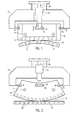
- a transfer tool 10 is formed as a substantially rectangular block, which may be made of a stainless steel part about two inches long. Apertures 14 are provided for mounting the tool 10 to a lapping fixture 52 (Fig. 4) to enable lapping and machining of a head slider bar 12 made of a ceramic material. Thin film transducer assemblies 20 and electrical contacts are uniformly spaced along the slider bar 12. During fabrication of the magnetic heads, the slider bar 12 which is bonded in place on the top surface of the transfer tool 10 is lapped, sectioned and configured to produce a row of head sliders.
- Fig. 1 illustrates the assembly with an undesirable row bow of the head slider bar 12.
- Fig. 2 illustrates the flexing of the transfer tool 10 by varying the pressure applied by the plunger 28 against the transfer 10 tool in order to obtain a collinear head slider bar resulting in uniform throat heights for the row of magnetic heads being processed. To ensure that the sliders are being lapped uniformly so that the throat heights of the thin film transducers are substantially the same, it is necessary to present a collinear array of transducers along the slider bar 12 to the lapping plate 54.
- notched ends 16 of the transfer tool 10 are closely engaged with fingers 22 of a bow yoke element 24.
- the transfer tool 10 has a central slot 32 in which a plunger 28 is captured.
- the notches 16 and slot 32 are instrumental in allowing changes in row bow of the tool 10 and attached slider bar 12.
- the transfer tool 10 and the supporting bow yoke 24 which grasps the tool 10 are mounted and locked to a nonrotary lapping fixture 52, so that the air bearing surfaces of the magnetic transducers 20 are positioned in a closely spaced relation relative to the lapping plate 54 (see Fig. 4).
- the lapping plate 54 has an abrasive surface that serves to grind and lap the air bearing surfaces of the magnetic heads being processed.
- the heads 20 are brought into contact with the lapping plate 54.
- Row bow is adjusted by means of a plunger 28 that is joined to a piston rod 30.
- the plunger 28 extends through a passageway in the yoke 24 and is captured in a slot 32 in the transfer tool 10.
- an enlarged cylindrical portion 29 is disposed within a slot 32 formed in the transfer tool 10 whereby up or down movement of the plunger 28 within the slot can vary the pressure against the area of the tool adjacent to the lower surface of the slot 32.
- Such variations in the application of pressure result in bending of the transfer tool 10, thus causing the row of heads to become collinear relative to the face of the rotary lapping plate 54.
- the lapping fixture 52 is mechanically linked to a plate 58. Ceramic feet 56 are attached to the plate 58 and ride on the abrasive lapping plate 54.
- the lapping fixture 52 is free to move parallel to the longitudinal axis of the ceramic bar 12.
- One end of the fixture 52 is connected to a tooling ball 100 which in turn is connected through a lever part 108 to the plate 58.
- the plate 58 is coupled to a movable element 50 by a hinge 62.
- the movable element 50 is mounted to a stationary post 64 that is fixed to the housing of the lapping assembly.
- a motor 66 is mechanically connected by a crank 92 and link 97 to the plate 58.
- the plate 58 oscillates so that the lapping fixture 52 is moved arcuately relative to the surface of the rotating lapping plate 54.
- the lapping fixture 52 moves longitudinally relative to the lapping plate 54. In this way, the combined motion of the rotating lapping plate 54 and the lapping fixture 52 results in effectively lapping the air bearing surface of the ceramic slider bar 12 on which the thin film transducers are deposited.
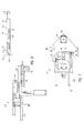
- an automatic control system As illustrated in Fig. 3, is employed.
- digital signals are obtained through electronic throat height circuitry connected to three spaced heads 20 on the slider bar 12.
- One of the selected heads is at the center C, and the other two selected heads 3L and 3R are close to the opposing ends of the bar 12, preferably the third head element from each end of the bar.
- a PC board 68 is mounted to the transfer tool 10 by means of adhesive.
- the PC board 68 has probe contacts 70 with leads 71 extending to bond pads 72, which in turn are connected to the circuitry of the three selected heads by two wires 73 to each head.
- the probe contacts 70 provide a relatively large area for six mechanical probes associated with the electronic circuitry for measuring throat height.
- Separate electronic circuits 74a, 74b, 74c which preferably are M-H looper circuits such as mentioned above, generate data signals representing the distance from zero throat height of each of the selected heads.
- the circuits compare the generated data signals to stored data signals representing optimum throat heights for magnetic heads of the same design.
- the stored data signals were obtained empirically by testing a significant number of such heads and recording the data referenced to throat height.
- the data signals are digitized and processed in signal processors 76a, 76b, 76c respectively and are passed through an RS232 port to an autolap control computer 78.
- the computer 78 processes the digital signals and generates control signals that are directed to an I/O card 80.
- the control signals are used to control (a)-the pressure from 0 to 100 pounds of force, for example, for modifying row bow; (b) the direction of change of the row bow; (c) shifting of a weight seated on the lapping fixture; (d) the air cylinder that controls the polishing step after lapping; and (e) the taper finish of the slider 12.
- a control signal from the I/O card 80 is directed to a variable pressure regulator 82, which comprises a current-to-pressure transducer, that has an air inflow and provides an air outflow which is proportional to the amount of pressure needed to modify the row bow, as calculated by the computer 78.
- the air cylinder 34 moves the piston rod 30 and the attached plunger 28 up or down. Air applied to the cylinder top pushes the piston rod 30 and plunger 28 downwards, whereas air applied to the cylinder bottom pushes the rod and plunger upwards.
- the direction of movement of the cylinder and thus the direction of change of row bow is controlled by a direction control signal received from the computer 78 and applied through two electric valves 86 to the air cylinder 34.
- the amount of deflection in either direction of the tool 10 at the air bearing surface of the heads can be controlled in the range of 0-.000150 inch, by way of example.
- a weight 88 is mounted on orthogonally disposed roller slides 36 and 38 seated on the lapping element, as shown in Fig. 10.
- the roller slides allow the weight to be shifted in a first direction parallel to the linear direction of the ceramic bar 12 and in a second direction perpendicular to the first direction.
- the weight which may be a mass of about 1 kilogram is shifted a distance proportional to the amount of lapping needed along sections of the slider bar 12.
- the weight 88 is moved in a direction parallel to the longitudinal axis of the transfer tool 10 for a distance determined by the computer.
- a control signal is sent to a stepper motor 90, which is mechanically connected by a crank 89 to the weight 88 to allow shifting the weight incrementally in a direction that will result in an increase of lapping pressure applied towards one end of the slider bar and a decrease of lapping pressure towards the other end of the slider bar.
- the weight 88 is shifted away from the slider bar 12 by the polish air cylinder 98 and a polish finishing step is initiated.
- the computer command signal opens an electric valve to allow a polishing compound to be distributed across the lapping plate 54.
- the polishing operation in effect washes away any residue of abrasive diamond slurry used during lapping.
- the duration of the polishing step runs about one minute for the implementation disclosed herein.
- the lapping fixture 52 and the transfer tool 10 and attached slider bar 12 are tilted at a predetermined angle.
- the head sliders spaced along the slider bar 12 are configured with air bearing rails that extend from a leading edge to a trailing edge of the slider at which end the thin film transducers are deposited, as is well known in the art.
- the tool 10 and slider bar 12 are tilted by a mechanism 96.
- the abrasive lapping plate 54 is used to form the tapers on the slider rails to enhance the aerodynamics of the air bearing slider structure.
- a mechanism for forming the tapers on the slider rails includes an air valve 101 that supplies pressure to an air cylinder 102.
- the air cylinder causes a taper slide cam 104 to move forward.
- a lifter 106 which rides on the slope or tapered portion of the cam 104 rises to lift a lever 108 that is tied at one end to a fixed pivot 110.
- the lever 108 supports a rod 112 and attached ball 100, so that as the lever is rotated about the pivot 110, the ball 100 is engaged within a socket 114 formed in the lapping fixture 52.
- the fixture 52 to which the transfer tool 10 and slider bar 12 are mounted is tilted, whereby the end portions of the slider rails are ground by the lapping plate 54 to a desired angle.
- the sequence of operation of the automated lapping system is set forth in the logic diagram of Fig. 5.
- a rapid and precise lapping and polishing of thin film magnetic heads are achieved with a significant increase in production yield.
- Uniformity of throat height level for a production run of thin film heads is realized so that optimum transducing performance of the heads is obtained.
- the rocking forces which are present with conventional lapping fixtures are reduced so that a single point and direction of resolution of lapping forces results.
- the bow yoke element may have recesses or apertures formed therein and the transfer tool may have extensions or fingers for engaging said recesses or apertures.
- an electrical solenoid or other actuating means may be used instead of pneumatic means to flex the transfer tool.
- the present invention may also be applicable to fabrication of other kinds of transducer apart from thin film magnetic heads, and to transducers formed on other kinds of supports apart from ceramic bars.
Landscapes
- Engineering & Computer Science (AREA)
- Manufacturing & Machinery (AREA)
- Mechanical Engineering (AREA)
- Human Computer Interaction (AREA)
- Physics & Mathematics (AREA)
- General Physics & Mathematics (AREA)
- Automation & Control Theory (AREA)
- Adjustment Of The Magnetic Head Position Track Following On Tapes (AREA)
- Magnetic Heads (AREA)
- Finish Polishing, Edge Sharpening, And Grinding By Specific Grinding Devices (AREA)
- Grinding And Polishing Of Tertiary Curved Surfaces And Surfaces With Complex Shapes (AREA)
Applications Claiming Priority (2)
| Application Number | Priority Date | Filing Date | Title |
|---|---|---|---|
| US673651 | 1991-03-22 | ||
| US07/673,651 US5203119A (en) | 1991-03-22 | 1991-03-22 | Automated system for lapping air bearing surface of magnetic heads |
Publications (2)
| Publication Number | Publication Date |
|---|---|
| EP0504887A2 true EP0504887A2 (fr) | 1992-09-23 |
| EP0504887A3 EP0504887A3 (en) | 1992-10-21 |
Family
ID=24703539
Family Applications (1)
| Application Number | Title | Priority Date | Filing Date |
|---|---|---|---|
| EP19920104796 Withdrawn EP0504887A3 (en) | 1991-03-22 | 1992-03-19 | Automated system for lapping magnetic heads |
Country Status (3)
| Country | Link |
|---|---|
| US (1) | US5203119A (fr) |
| EP (1) | EP0504887A3 (fr) |
| JP (1) | JPH05123960A (fr) |
Cited By (8)
| Publication number | Priority date | Publication date | Assignee | Title |
|---|---|---|---|---|
| EP0687525A1 (fr) * | 1994-06-13 | 1995-12-20 | Read-Rite Corporation | Système à roder pour le contournage automatisé |
| EP0686076A4 (fr) * | 1993-02-23 | 1996-01-17 | ||
| WO1996024466A1 (fr) * | 1995-02-06 | 1996-08-15 | Advanced Micro Devices, Inc. | Polissage chimique-mecanique d'articles minces faisant appel a une technique de polissage pulse |
| EP0779624A1 (fr) * | 1995-12-13 | 1997-06-18 | Quantum Corporation | Procédé et dispositif pour le rodage de patins |
| US6045431A (en) * | 1997-12-23 | 2000-04-04 | Speedfam Corporation | Manufacture of thin-film magnetic heads |
| US6212761B1 (en) | 1997-10-28 | 2001-04-10 | Tdk Corporation | Method for manufacturing thin-film magnetic head |
| WO2001056743A1 (fr) * | 2000-02-07 | 2001-08-09 | Seagate Technology Llc | Ensemble interface pour retroaction de commande de rodage |
| US7662021B2 (en) | 2007-04-17 | 2010-02-16 | Hitachi Global Storage Technologies Netherlands B.V. | Lapping plate texture for increased control over actual lapping force |
Families Citing this family (57)
| Publication number | Priority date | Publication date | Assignee | Title |
|---|---|---|---|---|
| US5386666A (en) * | 1993-02-11 | 1995-02-07 | Read-Rite Corporation | Automated system for controlling taper length during the lapping of air bearing surface of magnetic heads |
| JP3311116B2 (ja) * | 1993-10-28 | 2002-08-05 | 株式会社東芝 | 半導体製造装置 |
| US5531017A (en) * | 1994-02-14 | 1996-07-02 | International Business Machines Corporation | Thin film magnetic head fabrication method |
| JP2846235B2 (ja) * | 1994-02-17 | 1999-01-13 | ティーディーケイ株式会社 | ヘッドピース集合体加工用治具及び薄膜磁気ヘッドの製造方法 |
| US5733175A (en) | 1994-04-25 | 1998-03-31 | Leach; Michael A. | Polishing a workpiece using equal velocity at all points overlapping a polisher |
| US5607341A (en) | 1994-08-08 | 1997-03-04 | Leach; Michael A. | Method and structure for polishing a wafer during manufacture of integrated circuits |
| US5669804A (en) * | 1994-10-25 | 1997-09-23 | Sony Corporation | Magnetic tape surface treatment method and apparatus |
| US5749769A (en) * | 1994-12-16 | 1998-05-12 | International Business Machines Corporation | Lapping process using micro-advancement for optimizing flatness of a magnetic head air bearing surface |
| US5735036A (en) * | 1994-12-16 | 1998-04-07 | International Business Machines Corporation | Lapping process for minimizing shorts and element recession at magnetic head air bearing surface |
| US5603156A (en) * | 1994-12-16 | 1997-02-18 | International Business Machines Corporation | Lapping process for minimizing shorts and element recession at magnetic head air bearing surface |
| US5620356A (en) * | 1995-01-27 | 1997-04-15 | Lackey; Stanley | Row tool balance and bow correction apparatus |
| US5632669A (en) * | 1995-05-26 | 1997-05-27 | Censtor Corporation | Interactive method for lapping transducers |
| US5607340A (en) * | 1995-06-06 | 1997-03-04 | Lackey; Stanley A. | Row tool |
| US5951371A (en) * | 1996-11-04 | 1999-09-14 | Seagate Technology, Inc. | Multi-point bending of bars during fabrication of magnetic recording heads |
| USRE38340E1 (en) * | 1996-11-04 | 2003-12-02 | Seagate Technology Llc | Multi-point bending of bars during fabrication of magnetic recording heads |
| US6287170B1 (en) * | 1996-12-13 | 2001-09-11 | Seagate Technology Llc | Multipoint bending apparatus for lapping heads of a data storage device |
| US6475064B2 (en) | 1996-12-13 | 2002-11-05 | Seagate Technology Llc | Multipoint bending apparatus for lapping heads of a data storage device |
| JP3589546B2 (ja) * | 1997-04-08 | 2004-11-17 | 富士通株式会社 | 自動ラッピング方法及びその装置 |
| JP3403605B2 (ja) * | 1997-04-08 | 2003-05-06 | 富士通株式会社 | 部材接着方法及び部材接着装置 |
| JPH10286766A (ja) * | 1997-04-10 | 1998-10-27 | Fujitsu Ltd | 薄膜素子の自動ラッピング方法及びその装置 |
| US5967878A (en) * | 1997-04-25 | 1999-10-19 | International Business Machines Corporation | Lapping method and system for compensating for substrate bow |
| US5963401A (en) * | 1997-09-29 | 1999-10-05 | Storage Technology Corporation | Magnetic tape head assembly including modules having a plurality of magneto-resistive head elements |
| US5997381A (en) * | 1997-09-29 | 1999-12-07 | Storage Technology Corporation | Lapping sensor for thin film recording elements and method for manufacturing same |
| US5953184A (en) * | 1997-09-30 | 1999-09-14 | Storage Technology Corporation | Transverse slotted magnetic tape head assembly |
| US5923506A (en) * | 1997-10-03 | 1999-07-13 | Storage Technology Corporation | Recording head element with improved coil tap and method for manufacturing same |
| US6002554A (en) * | 1997-10-03 | 1999-12-14 | Storage Technology Corporation | Multitrack coupled element read head with support structure to eliminate shorting and method for manufacturing same |
| US6038108A (en) * | 1997-11-21 | 2000-03-14 | Storage Technology Corporation | Magnetic tape head assembly having segmented heads |
| USD420372S (en) * | 1998-06-25 | 2000-02-08 | Tdk Corporation | Jig for lapping magnetic heads |
| USD427615S (en) * | 1999-03-11 | 2000-07-04 | Tdk Corporation | Jig for lapping magnetic heads |
| USD423025S (en) * | 1998-06-25 | 2000-04-18 | Tdk Corporation | Jig for lapping magnetic heads |
| JP2000158335A (ja) * | 1998-11-27 | 2000-06-13 | Alps Electric Co Ltd | 定寸ラップ装置 |
| US6428715B1 (en) | 1998-12-22 | 2002-08-06 | International Business Machines Corporation | Method for producing sliders |
| US6174218B1 (en) | 1999-04-21 | 2001-01-16 | International Business Machines Corporation | Bow compensated lapping |
| JP3638815B2 (ja) | 1999-04-21 | 2005-04-13 | 富士通株式会社 | ロウツール及び該ロウツールを使用したラッピングマシン |
| JP2001006128A (ja) * | 1999-06-21 | 2001-01-12 | Tdk Corp | 磁気変換素子の製造方法および装置、ならびに磁気ヘッドの製造方法および装置 |
| US6312313B1 (en) * | 1999-10-06 | 2001-11-06 | Intenational Business Machines Corporation | Non-linear transducer lay-out of thin film head wafer for fabrication of high camber and crown sliders |
| USD450069S1 (en) | 1999-11-25 | 2001-11-06 | Tdk Corporation | Jig for lapping magnetic heads |
| JP3877117B2 (ja) | 1999-12-07 | 2007-02-07 | 富士通株式会社 | ラッピング方法及びラッピング装置 |
| JP3628571B2 (ja) * | 1999-12-21 | 2005-03-16 | Tdk株式会社 | 加工用治具 |
| JP4006154B2 (ja) * | 2000-01-07 | 2007-11-14 | Tdk株式会社 | 磁気ヘッドの研磨装置及び研磨方法 |
| JP3537726B2 (ja) | 2000-02-08 | 2004-06-14 | 富士通株式会社 | 研磨のための方法及び装置並びにラッピング加工治具 |
| US6663477B1 (en) | 2000-05-11 | 2003-12-16 | International Business Machines Corporation | Complaint membrane for restraining a workpiece and applying uniform pressure during lapping to improve flatness control |
| JP3914006B2 (ja) * | 2000-06-16 | 2007-05-16 | Tdk株式会社 | 磁気ヘッド用研磨装置および方法 |
| JP2002050016A (ja) * | 2000-07-28 | 2002-02-15 | Fujitsu Ltd | 磁気ヘッドスライダの製造方法及び装置 |
| JP3789744B2 (ja) | 2000-10-27 | 2006-06-28 | 富士通株式会社 | ラッピング装置及びラッピング方法 |
| US6857937B2 (en) * | 2002-05-30 | 2005-02-22 | Komag, Inc. | Lapping a head while powered up to eliminate expansion of the head due to heating |
| US20040102140A1 (en) * | 2002-11-21 | 2004-05-27 | Wood Jeffrey H. | Contour following end effectors for lapping/polishing |
| US6846222B2 (en) * | 2003-03-04 | 2005-01-25 | Hitachi Global Storage Technologies Netherlands, B.V. | Multi-chambered, compliant apparatus for restraining workpiece and applying variable pressure thereto during lapping to improve flatness characteristics of workpiece |
| US7118452B2 (en) * | 2004-02-12 | 2006-10-10 | The Boeing Company | Pneumatically actuated flexible coupling end effectors for lapping/polishing |
| US7256963B2 (en) * | 2004-09-16 | 2007-08-14 | Quantum Corporation | Magnetic head with adaptive data island and mini-outrigger and methods of manufacture |
| US7271983B2 (en) | 2004-09-16 | 2007-09-18 | Quantum Corporation | Magnetic head with mini-outriggers and method of manufacture |
| US20070183091A1 (en) * | 2006-02-03 | 2007-08-09 | Saliba George A | Read/write head having varying wear regions and methods of manufacture |
| US9427842B1 (en) * | 2012-06-28 | 2016-08-30 | Western Digital Technologies, Inc. | Systems and methods for correcting read/write overlay errors in the manufacture of magnetic transducers for storage drives |
| US10850364B2 (en) | 2016-06-23 | 2020-12-01 | Western Digital Technologies, Inc. | Within-row stripe height and wedge angle control for magnetic recording read-write heads |
| US10702969B2 (en) | 2016-06-23 | 2020-07-07 | Western Digital Technologies, Inc. | Actuator tilt interposer for within-row lapping mount tool for magnetic recording read-write heads |
| US9881639B2 (en) * | 2016-06-23 | 2018-01-30 | Western Digital Technologies, Inc. | Within-row wedge angle control for magnetic recording read-write heads |
| CN110449999B (zh) * | 2019-08-22 | 2020-06-16 | 常山亚瑞轴承有限公司 | 一种轴承外圈制造加工方法 |
Family Cites Families (6)
| Publication number | Priority date | Publication date | Assignee | Title |
|---|---|---|---|---|
| US3977130A (en) * | 1975-05-12 | 1976-08-31 | Semimetals, Inc. | Removal-compensating polishing apparatus |
| US4517041A (en) * | 1982-09-30 | 1985-05-14 | Magnetic Peripherals Inc. | Method for attaching a workpiece to a workpiece carrier |
| US4457114A (en) * | 1982-09-30 | 1984-07-03 | Magnetic Peripherals Inc. | Workpiece carrier |
| US4536992A (en) * | 1983-11-04 | 1985-08-27 | Magnetic Peripherals | Precision lapping system |
| US4914868A (en) * | 1988-09-28 | 1990-04-10 | International Business Machines Corporation | Lapping control system for magnetic transducers |
| US4912883A (en) * | 1989-02-13 | 1990-04-03 | International Business Machines Corporation | Lapping control system for magnetic transducers |
-
1991
- 1991-03-22 US US07/673,651 patent/US5203119A/en not_active Expired - Fee Related
-
1992
- 1992-03-19 EP EP19920104796 patent/EP0504887A3/en not_active Withdrawn
- 1992-03-21 JP JP4094749A patent/JPH05123960A/ja active Pending
Cited By (10)
| Publication number | Priority date | Publication date | Assignee | Title |
|---|---|---|---|---|
| EP0686076A4 (fr) * | 1993-02-23 | 1996-01-17 | ||
| EP0687525A1 (fr) * | 1994-06-13 | 1995-12-20 | Read-Rite Corporation | Système à roder pour le contournage automatisé |
| WO1996024466A1 (fr) * | 1995-02-06 | 1996-08-15 | Advanced Micro Devices, Inc. | Polissage chimique-mecanique d'articles minces faisant appel a une technique de polissage pulse |
| EP0779624A1 (fr) * | 1995-12-13 | 1997-06-18 | Quantum Corporation | Procédé et dispositif pour le rodage de patins |
| US6212761B1 (en) | 1997-10-28 | 2001-04-10 | Tdk Corporation | Method for manufacturing thin-film magnetic head |
| US6678939B2 (en) | 1997-10-28 | 2004-01-20 | Tdk Corporation | System for manufacturing a thin film magnetic head |
| US6045431A (en) * | 1997-12-23 | 2000-04-04 | Speedfam Corporation | Manufacture of thin-film magnetic heads |
| WO2001056743A1 (fr) * | 2000-02-07 | 2001-08-09 | Seagate Technology Llc | Ensemble interface pour retroaction de commande de rodage |
| US6609949B2 (en) | 2000-02-07 | 2003-08-26 | Seagate Technology Llc | Interface assembly for lapping control feedback |
| US7662021B2 (en) | 2007-04-17 | 2010-02-16 | Hitachi Global Storage Technologies Netherlands B.V. | Lapping plate texture for increased control over actual lapping force |
Also Published As
| Publication number | Publication date |
|---|---|
| EP0504887A3 (en) | 1992-10-21 |
| JPH05123960A (ja) | 1993-05-21 |
| US5203119A (en) | 1993-04-20 |
Similar Documents
| Publication | Publication Date | Title |
|---|---|---|
| US5203119A (en) | Automated system for lapping air bearing surface of magnetic heads | |
| US5117589A (en) | Adjustable transfer tool for lapping magnetic head sliders | |
| US5620356A (en) | Row tool balance and bow correction apparatus | |
| US5386666A (en) | Automated system for controlling taper length during the lapping of air bearing surface of magnetic heads | |
| US6196897B1 (en) | Automatic lapping method and a lapping apparatus using the same | |
| US6174218B1 (en) | Bow compensated lapping | |
| US5525091A (en) | Multi-adjustable row transfer tool | |
| US5951371A (en) | Multi-point bending of bars during fabrication of magnetic recording heads | |
| US6050878A (en) | Processing jig | |
| US6238276B1 (en) | Sizing lapping apparatus | |
| JP3926565B2 (ja) | 研磨装置、研磨方法及び磁気ヘッドの製造方法 | |
| JPH1116124A (ja) | 磁気ヘッドの研磨方法及び装置 | |
| US6315636B1 (en) | Lapping machine, row tool, and lapping method | |
| KR100417775B1 (ko) | 피가공물 가공장치 및 가공방법 | |
| US6846222B2 (en) | Multi-chambered, compliant apparatus for restraining workpiece and applying variable pressure thereto during lapping to improve flatness characteristics of workpiece | |
| JP3837036B2 (ja) | 磁気ヘッド製造工程における研磨量測定装置および方法 | |
| US5624298A (en) | Jig for headpiece aggregate machining and method for manufacturing a thin film magnetic head | |
| US6991513B2 (en) | Magnetic head grinding device and method | |
| US6623336B2 (en) | Magnetic head polishing device and method thereof | |
| US6565414B2 (en) | Polishing apparatus for magnetic head and method therefor | |
| US6315633B1 (en) | Processing jig | |
| EP0687525A1 (fr) | Système à roder pour le contournage automatisé | |
| JPH08129716A (ja) | 磁気ヘッド構造体の研磨方法及びその装置並びに磁気ディスク装置 | |
| JPH087231A (ja) | Mr複合薄膜磁気ヘッドのmr高さ加工方法 | |
| JP2004071016A (ja) | 磁気ヘッドスライダの研磨加工装置および薄膜磁気ヘッドの製造方法 |
Legal Events
| Date | Code | Title | Description |
|---|---|---|---|
| PUAI | Public reference made under article 153(3) epc to a published international application that has entered the european phase |
Free format text: ORIGINAL CODE: 0009012 |
|
| PUAL | Search report despatched |
Free format text: ORIGINAL CODE: 0009013 |
|
| AK | Designated contracting states |
Kind code of ref document: A2 Designated state(s): DE FR GB NL |
|
| AK | Designated contracting states |
Kind code of ref document: A3 Designated state(s): DE FR GB NL |
|
| 17P | Request for examination filed |
Effective date: 19930325 |
|
| STAA | Information on the status of an ep patent application or granted ep patent |
Free format text: STATUS: THE APPLICATION HAS BEEN WITHDRAWN |
|
| 18W | Application withdrawn |
Withdrawal date: 19940310 |