EP0505104A1 - Raumsparende Verschlussvorrichtung für optisches Kabel - Google Patents
Raumsparende Verschlussvorrichtung für optisches Kabel Download PDFInfo
- Publication number
- EP0505104A1 EP0505104A1 EP92302163A EP92302163A EP0505104A1 EP 0505104 A1 EP0505104 A1 EP 0505104A1 EP 92302163 A EP92302163 A EP 92302163A EP 92302163 A EP92302163 A EP 92302163A EP 0505104 A1 EP0505104 A1 EP 0505104A1
- Authority
- EP
- European Patent Office
- Prior art keywords
- closure
- fiber
- cable
- portions
- optical fiber
- Prior art date
- Legal status (The legal status is an assumption and is not a legal conclusion. Google has not performed a legal analysis and makes no representation as to the accuracy of the status listed.)
- Granted
Links
- 239000013307 optical fiber Substances 0.000 title claims abstract description 40
- 239000000835 fiber Substances 0.000 claims abstract description 68
- 238000009826 distribution Methods 0.000 claims abstract description 28
- 238000005192 partition Methods 0.000 claims description 6
- 239000000463 material Substances 0.000 claims description 3
- 230000006641 stabilisation Effects 0.000 claims 2
- 238000011105 stabilization Methods 0.000 claims 2
- 230000000087 stabilizing effect Effects 0.000 claims 2
- 210000005069 ears Anatomy 0.000 description 8
- 239000006261 foam material Substances 0.000 description 6
- 239000004020 conductor Substances 0.000 description 5
- 239000003381 stabilizer Substances 0.000 description 5
- 238000003860 storage Methods 0.000 description 5
- 230000006835 compression Effects 0.000 description 4
- 238000007906 compression Methods 0.000 description 4
- 210000002445 nipple Anatomy 0.000 description 4
- 238000005452 bending Methods 0.000 description 3
- 230000005540 biological transmission Effects 0.000 description 3
- 230000004927 fusion Effects 0.000 description 3
- 238000007789 sealing Methods 0.000 description 2
- 230000004888 barrier function Effects 0.000 description 1
- 238000004891 communication Methods 0.000 description 1
- 238000010276 construction Methods 0.000 description 1
- 239000000356 contaminant Substances 0.000 description 1
- 230000009977 dual effect Effects 0.000 description 1
- 239000008393 encapsulating agent Substances 0.000 description 1
- 239000011152 fibreglass Substances 0.000 description 1
- 239000006260 foam Substances 0.000 description 1
- 239000011521 glass Substances 0.000 description 1
- 230000001771 impaired effect Effects 0.000 description 1
- 238000009434 installation Methods 0.000 description 1
- 238000005304 joining Methods 0.000 description 1
- 238000000034 method Methods 0.000 description 1
- 238000002360 preparation method Methods 0.000 description 1
- 230000001681 protective effect Effects 0.000 description 1
- 230000008707 rearrangement Effects 0.000 description 1
Images


Classifications
-
- G—PHYSICS
- G02—OPTICS
- G02B—OPTICAL ELEMENTS, SYSTEMS OR APPARATUS
- G02B6/00—Light guides; Structural details of arrangements comprising light guides and other optical elements, e.g. couplings
- G02B6/44—Mechanical structures for providing tensile strength and external protection for fibres, e.g. optical transmission cables
- G02B6/4439—Auxiliary devices
- G02B6/444—Systems or boxes with surplus lengths
- G02B6/4441—Boxes
- G02B6/4442—Cap coupling boxes
-
- G—PHYSICS
- G02—OPTICS
- G02B—OPTICAL ELEMENTS, SYSTEMS OR APPARATUS
- G02B6/00—Light guides; Structural details of arrangements comprising light guides and other optical elements, e.g. couplings
- G02B6/44—Mechanical structures for providing tensile strength and external protection for fibres, e.g. optical transmission cables
- G02B6/4439—Auxiliary devices
- G02B6/444—Systems or boxes with surplus lengths
- G02B6/4453—Cassettes
- G02B6/4454—Cassettes with splices
-
- G—PHYSICS
- G02—OPTICS
- G02B—OPTICAL ELEMENTS, SYSTEMS OR APPARATUS
- G02B6/00—Light guides; Structural details of arrangements comprising light guides and other optical elements, e.g. couplings
- G02B6/44—Mechanical structures for providing tensile strength and external protection for fibres, e.g. optical transmission cables
- G02B6/4439—Auxiliary devices
- G02B6/4471—Terminating devices ; Cable clamps
- G02B6/44775—Cable seals e.g. feed-through
-
- G—PHYSICS
- G02—OPTICS
- G02B—OPTICAL ELEMENTS, SYSTEMS OR APPARATUS
- G02B6/00—Light guides; Structural details of arrangements comprising light guides and other optical elements, e.g. couplings
- G02B6/44—Mechanical structures for providing tensile strength and external protection for fibres, e.g. optical transmission cables
- G02B6/4439—Auxiliary devices
- G02B6/444—Systems or boxes with surplus lengths
- G02B6/4441—Boxes
- G02B6/4442—Cap coupling boxes
- G02B6/4445—Divided base plates
Definitions
- This invention relates to a space-saving optical fiber cable closure having enhanced storage capability.
- fiber slack normally must be provided adjacent to splices.
- splicing optical fibers by mechanical means or by fusion, it becomes necessary to provide enough slack fiber so that the fiber can be pulled out of a closure for the preparation of fiber ends and the joining together.
- the splices should be easily accessible to facilitate the rearrangement of the optical fibers and splices.
- a closure should be capable of accommodating at least the more popular of these splicing arrangements.
- a closure which is particularly suited in the fiber-in-the-loop market and to splice relatively small count optical fiber cables some of which are referred to as drop cables.
- what is sought after is a closure that is relatively inexpensive to serve this very large market.
- the sought after closure is relatively small in size yet able to accommodate a relatively large number of splices.
- fiber splice closures are available in the prior art. Some of these prior art closures have shortcomings. Typically, they have been somewhat complex, difficult to use and difficult to access. Some prior art splice closures have included organizers which have tended to place higher than desired stresses on the optical fibers, resulting in fiber damage. In addition, these prior art closures often have failed to provide simple to use, positive means for routing the optical fibers in an effective manner and for storing slack.
- a device having a modular construction which is suitable for installation in standard splice closures.
- the device comprises a plurality of tray-like members each adapted to retain and store at least one fiber.
- the device provides access to the individual fibers contained in the trays.
- the trays are stacked one on top of the other, and each is hinged separately at one end thereof to a carrier, thus allowing them to move relative to one another like bound pages.
- Each tray-like support has a width which is adequate to provide the minimum bending radius specified for that fiber.
- a support member in a support member includes a base for supporting an optical fiber breakout and a plurality of splice trays.
- the breakout allows a user to separate fibers into groups before they are routed to ones of the trays.
- a tubular cover having a closed end and an open end is adapted to receive and be sealed to a cable termination assembly.
- the cable termination assembly includes cable entry facilities through which the cables to be spliced are routed.
- a support member extends from the cable entry facilities and has a free end disposed adjacent to the closed end of the cover.
- the support member includes a support base for supporting an optical fiber breakout and a plurality of optical fiber splice trays.
- each tray Mounted centrally of each tray is at least one organizing module each of which is capable of holding a plurality of optical fiber connective arrangements.
- Each module is such that it is capable of accommodating different kinds of connective arrangements such as, for example, fusion splices and cleave, sleeve, and leave splicing connectors.
- Each tray is capable of holding a plurality of organizing modules which may be added as needed.
- optical fiber cable closure which is relatively small in size and which is relatively inexpensive.
- the sought after closure should have suitable storage capability and also the capability to store different kinds of splicing arrangements.
- the optical fiber support means includes a distribution portion which is connected to and cantilevered from the cable entry portion, and fiber organizing means mounted to the distribution portion and cooperating with the distribution portion to provide a chamber for holding excess fiber length.
- the fiber organizing means is capable of holding a plurality of the organizing modules in stacked relationship to one another.
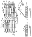
- FIG 1 there is shown an optical fiber cable closure which is designated generally by the numeral 20.
- the closure 20 is suitable, for example, for use in fiber-in-the-loop.
- FIG. 2 there is shown a closure 20 in which distribution cables 21 and 22 extend into the closure and are spliced to drop cables 23 and 24 which extend from the closure to a customer or to a distant terminal 25. From the distant terminal, media (not shown) extend to the customer.
- the closure 20 includes a cable splicing termination assembly which is designated generally by the numeral 26 (see FIGS. 1, 3 and 4) and in which optical fibers 27-27 are spliced and/or stored and a cover 28.
- the cover 28 is cylindrically shaped and includes an open end 29 and a closed end 30.
- An axis 32 of the closure extends from the open end 29 of the cover to the closed end 30.
- the cable splicing termination assembly 26 includes a cable entry portion 31.
- the cable entry portion 31 includes an end plate assembly 34 a portion of which is disc-shaped.
- the end plate assembly 34 preferably is made of a molded, glass-reinforced plastic material.
- Each end plate assembly 34 includes two portions 36 and 38 (see FIG. 5).
- the portion 36 includes a partially circular Flange 40, an outwardly projecting portion 42 and an inwardly projecting portion 44 (see also FIG. 3).
- the outwardly projecting portion 42 includes a housing portion 46 (see FIG. 5) having an extension which is designated generally by the numeral 48.
- the extension 48 includes two semi-circular conduits 47-47 which are disposed between landings 49-49 of the extension. Each of the landings 49-49 is provided with a threaded opening 45.
- the inwardly extending portion 44 includes a housing portion 50 from which extends a landing portion 51 comprising spaced ears.
- each of the openings is adapted to allow a preterminated drop cable to extend therethrough.
- An inner end of each opening 52 is threaded internally.
- Each nipple is adapted to receive a rubber-like sheath sealing plug 54 (see FIGS. 6 and 7) and to have a compression collar 55 (see also FIG. 3) turned threadably thereover to seal the closure.
- the compression collar 55 includes a portion 56, which, when the collar is turned, grips the cable and prevents undesired pullout and/or rotation.
- a craftsperson When it is desired to extend a drop cable into the closure, a craftsperson removes an assembly comprising a protective tube 57 which includes a cap (see FIG. 7) from an end portion of the drop cable which may have fiber preterminated with ST® connectors 60-60, for example, and with a portion of the sheath thereof removed.
- the preterminated drop cables each include an end portion which extends through a compression collar 55, a grip portion 56 and a sealing plug 54 and through waterblocking provisions 59.
- the waterblocking provisions may be those described in copending application Serial No. 07/443,300 filed on November 29, 1989 in the name of G. S. Cobb.
- the end portion of the drop cable is inserted through the end plate assembly 34 (see FIG. 8) and then the plug 54 is inserted into the nipple and the compression collar 55 turned threadably onto the nipple 53 to compress the rubber-like plug about the cable to seal the cable at its passage through the end plate assembly.
- the portion 36 of the end plate assembly also includes a relatively thin web 58 (see FIG. 5) having a generally circular configuration.
- the web 58 is sufficiently thin to allow it to be removed easily to allow a rubber bushing to be inserted into the end plate assembly 34 and an external ground wire to be extended through the bushing.
- the end plate assembly 34 also includes a portion 38.
- the portion 38 includes an arcuately shaped flange 61 (see FIGS. 5 and 9) having inner and outer portions 63 and 65 projecting therefrom (see FIG. 9).
- the inner portion 63 includes a housing portion 67 which includes a post 68 disposed therein and from which a threaded stud 69 extends upwardly.
- the inner portion 63 includes three spaced ears 71-71 projecting inwardly longitudinally of the closure.
- Each ear 71 includes an opening 73 therein.
- the openings 73-73 are aligned with threaded openings 75-75 (see FIG. 3) which are formed in the ears of the landing 51 to permit bolts 74-74 (see also FIG. 1) to be inserted through the openings 73-73 and turned into the threaded openings 75-75 of the ears.
- the outer portion 65 includes three spaced ears 76-76 each having an aperture 77 therein.
- each two ears 76-76 Disposed between each two ears 76-76 is an arcuately formed surface 79 which when the portions 36 and 38 are assembled together cooperates with an arcuately shaped surface of the outwardly projecting portion 42 of the upper portion 36 to provide a conduit for a cable 21 or 22 to be spliced. Also, when the portions 36 and 38 are assembled together, the apertures 77-77 of the outer portion of the portion 38 become aligned with the threaded openings 45-45 in the outwardly projecting portion of the portion 36 so that bolts may be used to secure together the two outwardly extending portions.
- a gasket 72 (see FIG. 9) is disposed between the portions 36 and 38 of the end plate assembly 34 to provide a seal between those two portions when assembled together and about the distribution cables which extend into the end plate assembly and about cable cores which extend out of the cable end plate assembly and farther into the closure.
- Different gaskets may be used to accommodate different cable sizes through the portions of the gaskets which are disposed in engagement with the arcuately formed surfaces of the housing portions.
- Shim washers (not shown) may be disposed over the threaded stud 69, depending on the size of cables used, in order to keep the cable cores centered within the openings in the interior housing portions.
- two cables 21 and 22 extend through the end plate assembly 34, each one through a conduit formed between two arcuately shaped portions of the cooperating outwardly projecting portions of the portions 36 and 38 of the end plate assembly and then out from within the assembled housing portions 50 and 67 through the two exit ports formed by arcuately shaped portions of the inwardly projecting portions of the portions 36 and 38.
- Also extending through the end plate assembly 34 is one or more drop cables. As is seen, the end plate assembly 34 is adapted to permit as many as four drop cables to extend therethrough.
- Each sheath gripping arrangement 80 includes an arcuately shaped shoe plate 82 which engages a jacketed portion of a distribution cable, for example, cable 21, which extends into the housing.
- Each shoe plate is connected to a bifurcated upstanding leg 83 which is bolted to a block 84.
- Each block 84 is bolted to a T-shaped portion 86 of a metallic stabilizer bar 87 which itself has an opening 88.
- the stabilizer bar 87 is positioned in the housing to cause the threaded stud 69 to protrude through the opening 88 to receive a nut to fasten the stabilizer bar to the housing. Further, the stud 69 protrudes through an opening in the housing portion 50 and is used for grounding purposes.
- Metallic strength members of the cable may be turned upwardly and received between the bifurcated portions of the upstanding leg 83 and associated block 84.
- Fastened to an opposite side of the block 84 is an upstanding portion 89 of an electrical bonding device which includes a curved plate 90 which engages a plate 92 which has been inserted between a metallic shield of the cable and other components.
- a threaded stud 95 projects from the plate 92 through the plate 90 and is secured thereto by a nut 96.
- a device 98 having an opening for receiving an end portion of the central strength member is positioned to cause an extending plate 99 to abut the stud 95.
- a set screw 94 is used to secure the central strength member within the device 98.
- the stabilizer bar 87 performs several functions. It stabilizes the distribution cables 21 and 22 against rotation. Also, it prevents sheath pullout and provides electrical continuity from the distribution cables 21 and 22 to drop cables.
- the ground wires of drop cables are connected to the upstanding stud 69 and hence through the stabilizer bar to the bonding arrangements 80-80 to the cables 21 and 22.
- grounding wires 85-85 of drop wires which extend through the end plate assembly 34 and which are terminated in eyelets are connected to the threaded stud 69. This causes an electrical connection to be made between the drop cables and the distribution cables 21 and 22. Such an arrangement is called an internal grounding arrangement.
- An external grounding arrangement also may be used.
- an upper end of the threaded stud 69 extends through the housing portion 50 and has a grounding arrangement 100 connected thereto.
- the grounding arrangement 100 includes a foot 101 which extends from a box-like portion 102.
- An upper end of the stud 69 extends through an opening in the foot and is provided with a nut to secure the grounding arrangement to the top of the housing portion 50.
- a ground wire 103 which extends through the bushing in the opening 58 in the end plate 34 extends into the box-like portion 102 and is secured therein by a set screw 104.
- the assembly 105 includes a distribution portion 106 which includes end portions 107-107 (see also FIG. 4) each of which is aligned with one of the spaced ears of the portions 36 and 38.
- a bolt 74 extends through each pair of aligned ears of the internal housing portions of the portions 36 and 38 of the end plate assembly 34 and associated end portion 107 with a nut being turned on to each bolt to secure the optical fiber support assembly to the end plate assembly.
- the distribution portion 106 includes sidewalls 108-108 which are connected by an arcuately shaped end portion 109 and a base 110. Internally disposed within the distribution portion 106 between the sidewalls thereof are two arcuately configured partitions 111-111. At ends and sides of the distribution portion 106 are disposed overhanging portions 112-112 and 113-113, respectively. Excess fiber length conveniently may be stored within the distribution portion and arrangement to follow the curvature of the endwall and of the internally disposed partitions.
- a fiber organizer 115 (see FIG. 3) having a cutout 114.
- the fiber organizer includes cutout portions 116-116 which are received under portions 117-117 (see also FIG. 4) at one end of the distribution portion 106 and includes a compressible split finger 118 (see FIG. 13) at an opposite end.
- the split finger 118 is received within an opening of a bracket 119 of the distribution portion 106. As the split finger 118 is inserted into the opening in the bracket, the furcations are compressed and after a headed end has been moved through the opening in the bracket, the furcations move apart to lock the finger within the bracket and secure the organizer 115 to the distribution portion 106.
- the fiber organizer 115 is adapted to support a plurality of connective organizer modules such as splice holders 120-120 (see FIGS. 3 and 14-17).
- Each splice holder 120 includes two spaced apart T-shaped projections 122-122 each of which is adapted to have a stem 124 thereof received slidably in a slot 126 (see FIG. 3) extending along the backwall of the organizer 115 normal to a base 125 of the fiber organizer.
- the splice holders are stackable one upon the other with a bottom one of the splice holders supported in engagement with a raised portion or platform 128 of the fiber organizer 115.
- the small diameter optical fiber inadvertently may be moved beneath the bottom one of the splice holders and the platform 128, possibly resulting in damage to the fiber.
- a relatively thin, e.g. 1 mm, strip 127 of foam material is attached to a top surface of the platform 128.
- Each splice holder 120 includes a base having a plurality of slotted posts 129-129 upstanding at each end thereof and at two locations intermediate the ends. Extending between posts at each end and at one of the intermediate locations is a partition 132 with nests 134-134 being formed between adjacent partitions and between partitions and sidewalls. Each nest is adapted to receive any one of several splicing connectors such as, for example, AT&T's CSL Lightsplice system and rotary mechanical splice and 3M's Fiberlok optical fiber splice or to hold fusion splices.
- splicing connectors such as, for example, AT&T's CSL Lightsplice system and rotary mechanical splice and 3M's Fiberlok optical fiber splice or to hold fusion splices.
- nests 134-134 on a side of the center of the splice holder are offset from nests on the other side. It should be observed that the bifurcated posts 129-129 are disposed between adjacent nests. As a result of the position of the posts with respect to the nests and as a result of the offset longitudinally of the nests, the posts on one half of the splice holder are aligned with the nests on the opposite half. Also, at each end of each holder may be positioned a strip 136 of compliant material such as a foam material having a plurality of vertical slits 138-138 therein.
- Each slit is aligned with two spaced split posts on the adjacent side of the splice holder and with a longitudinal axis of the splicing connector in a nest on the opposite side of the holder. As each fiber extends past the center of a holder, it becomes disposed under an upper hook end of an arm 137.
- Each length of foam material also includes additional slits 139-139.
- Each of the additional slits is aligned with a longitudinal centerline of an adjacent nest.
- the fiber extending therefrom extends through a slit 139 in the foam material adjacent to an outer end of the splicing connector and extends through the two, aligned bifurcated posts and slit 138 of the foam material on the other half of the splice holder.
- the foam material is effective to help hold the fiber and hence the splicing connector within the nest.
- a lid 140 Disposed on top of the upper one of the stackable holders is a lid 140.
- the lid In order to attach the lid 140 to the upper one of the splice holders, the lid is provided with oppositely extending pins 142-142 at ends of one side thereof.
- Each splice holder is provided with holes 144-144 in wall portions 146-146 thereof at opposite ends of the holders. The wall portions 146-146 may be deflected outwardly to allow the pins 142-142 to be inserted into the holes to connect the lid to the upper one of the splice holders.
- the lid 140 is provided with a securing hook 150.
- the securing hook 150 is mounted pivotally to a side of the lid which is opposite to that side from which the pins 142-142 extend.
- the hook At an end opposite to its pivotal connection to the lid, the hook includes a U-shaped end portion 152.
- the length of the hook in the preferred embodiment is sufficiently long to extend across three of the stackable holders. With the holders stacked one upon the other, the hook 150 is moved pivotally to cause the U-shaped portion to engage an edge portion 154 of the cutout 114 of the organizer 115.
- the U-shaped portion is dimensioned to snap-lock onto an edge portion of the cutout 114 to secure together the three stacked splice holders.
- the U-shaped portion of the hook performs a dual function. Not only does it secure together the splice holders, but also an innermost leg 156 of the U-shaped portion becomes disposed between the lowermost splice holder 120 and the base of the fiber organizer 115 to hold the lowermost splice holder spaced above the base.
- the U-shaped portion of the hook 150 cooperates with the platform 128 to hold the lowermost splice holder above the base 125 of the fiber organizer to allow fiber to be disposed between the lowermost splice holder and the base of the fiber organizer.
- the lid 140 includes two spaced latching portions 160-160.
- Each of the latching portions 160-160 is adapted to snap-lock into engagement with a lip 162 (see FIG. 14) of an upper one of the splice holders 120-120.
- the arrangement of this invention provides ample space in which to route the fibers without going below the minimum bend radius.
- the splice holders are disposed adjacent to one side edge of the fiber organizer. This allows ample room to route the fiber from incoming cables to one or more of the splice holders with radii above the minimum bend radius. If the splice holders had been disposed in the middle portion of the fiber organizer, the width of the fiber organizer would have had to have been increased in order to maintain suitable bend radii for the fiber. Of course, by holding the width of the fibers organizer to a minimum consistent with suitable bend radii, the size of the closure is controlled, thereby achieving the goal of a reduced size closure for fiber-in-the loop use.
- closure of this invention accommodates different splicing devices or connectors. This may be accomplished because of the capability of removing easily one or all of the splice holders and replacing them with holders adapted to receive splice devices or connectors of the desired choice.
- the portions of the optical fiber distribution cables 21 and 22 which extend beyond the cable end plate assembly 34 into the cable splice support assembly 32 have the shields and other sheath components removed therefrom. Only a core tube or tubes of each cable extends through the end plate assembly 34 and extends into engagement with the distribution portion 106. If the cable is of the ribbon type, a craftsperson may choose to route ribbons to splice holders without separating fibers and putting them into tubes.
- the craftsperson After the splicing has been accomplished as described earlier herein, the craftsperson causes a lid 140 to be applied over the outermost splice holder 120. Then the craftsperson assembles the splicing termination assembly 26 to the cover 28. An O-ring seal is caused to be disposed about the periphery of the arcuate portions 40 and 61 of the end plate assembly 34.
- the termination assembly 26 is inserted into the cover 28 after which a plurality of over-center clamping hooks 170-170 (see FIG. 1) are caused to become engaged with portions 172-172 of the splice termination assembly to hold the termination assembly in the cover 28.
- Each of the end plate assembly portions and the O-ring seal cooperate with the cover 28 to seal the closure against the unintended ingress of contaminants or the egress of pressurized air.
- the volume between the housing portions of the end plate portions 36 and 38 may be filled with a suitable encapsulant.
- a suitable encapsulant In the alternative, other suitable waterblocking arrangements may be used.
- the closure of this invention has many advantages over prior art closures. It has adequate storage capability for fiber-in-the loop use, not only in the number of optical fiber splices that may be stored in each splice holder, but also in the kinds of splicing arrangements which may be accommodated. Also, it is relatively small compared to other commercially available closures and is relatively inexpensive. Also, the closure may be used to splice or connect some of the fibers of a large fiber count cable with the other fibers thereof being passed through the closure.
- the fiber organizer has a capacity for three splice holders which are modular and each of which can accommodate eight splices. This is advantageous in that a stack of holders conforms to the six and twelve fiber units and ribbons which are typical in optical fiber cables.
- the organizer 115 is capable of having connector holders (not shown) mounted thereon.
- a connector holder which is capable of holding optical fiber connectors such as ST® connectors, for example, may have a plurality of projecting pins which are received in openings along a side edge of the organizer which is opposite to the side along which the splice holders 120-120 are disposed. Further, the splice holders 120-120 may be removed and replaced with a connector holder which is adapted to snap-lock into openings in the fiber organizer adjacent to the platform 128.
Landscapes
- Physics & Mathematics (AREA)
- General Physics & Mathematics (AREA)
- Optics & Photonics (AREA)
- Light Guides In General And Applications Therefor (AREA)
- Mechanical Coupling Of Light Guides (AREA)
Applications Claiming Priority (2)
| Application Number | Priority Date | Filing Date | Title |
|---|---|---|---|
| US673880 | 1991-03-22 | ||
| US07/673,880 US5097529A (en) | 1991-03-22 | 1991-03-22 | Space-saving optical fiber cable closure |
Publications (2)
| Publication Number | Publication Date |
|---|---|
| EP0505104A1 true EP0505104A1 (de) | 1992-09-23 |
| EP0505104B1 EP0505104B1 (de) | 1997-01-15 |
Family
ID=24704463
Family Applications (1)
| Application Number | Title | Priority Date | Filing Date |
|---|---|---|---|
| EP92302163A Expired - Lifetime EP0505104B1 (de) | 1991-03-22 | 1992-03-13 | Raumsparende Verschlussvorrichtung für optisches Kabel |
Country Status (5)
| Country | Link |
|---|---|
| US (1) | US5097529A (de) |
| EP (1) | EP0505104B1 (de) |
| JP (1) | JP2806406B2 (de) |
| CA (1) | CA2061911C (de) |
| DE (1) | DE69216666T2 (de) |
Cited By (15)
| Publication number | Priority date | Publication date | Assignee | Title |
|---|---|---|---|---|
| WO1995003560A1 (en) * | 1993-07-23 | 1995-02-02 | Raychem Corporation | Oval port seal |
| EP0645656A1 (de) * | 1993-09-29 | 1995-03-29 | WALTER ROSE GmbH & Co. KG | Vorrichtung für einen Muffeneingang, insbesondere für Glasfaserkabel |
| EP0657756A1 (de) * | 1993-12-09 | 1995-06-14 | Stewing Kunststoffbetrieb GmbH Dorsten | Muffengehäuse zum Verbinden, Abzweigen und Aufteilen von Kabeln, insbesondere der Bündeladern und ihrer Glasfasern von Glasfaserkabeln |
| WO1996038752A1 (en) * | 1995-05-30 | 1996-12-05 | The Whitaker Corporation | Optical fiber splice holder and strain relief |
| WO1998008125A3 (en) * | 1996-08-22 | 1998-05-22 | Raychem Sa Nv | Optical fibre splice closure |
| EP0871909A4 (de) * | 1995-09-29 | 1999-06-02 | Psi Telecommunications | Gehause fur ein faseroptisches kabel |
| WO1999042882A1 (en) * | 1998-02-20 | 1999-08-26 | Alcoa Fujikura Ltd. | Fiber optic splice enclosure |
| FR2790608A1 (fr) * | 1999-03-05 | 2000-09-08 | Rxs Morel Accessoires De Cable | Cassette notamment pour fibres optiques ou fils conducteurs |
| EP1736807A1 (de) * | 2005-06-22 | 2006-12-27 | CCS Technology, Inc. | Vorrichtung zur Abfangung von in Mikroducts geführten Mikrokabeln sowie der Mikroducts |
| EP1744191A1 (de) * | 2005-06-22 | 2007-01-17 | CCS Technology, Inc. | Vorrichtung zur Abfangung von Kabeln |
| WO2011089218A1 (en) * | 2010-01-22 | 2011-07-28 | Wavin B.V. | Pipe connector |
| US9977211B1 (en) | 2017-04-21 | 2018-05-22 | Afl Telecommunications Llc | Optical connection terminals for fiber optic communications networks |
| US10281670B2 (en) | 2015-01-12 | 2019-05-07 | Afl Telecommunications Llc | Fiber optic terminal enclosure |
| US10520692B2 (en) | 2015-11-11 | 2019-12-31 | Afl Telecommunications Llc | Optical connection terminals for fiber optic communications networks |
| DE212023000045U1 (de) | 2022-07-06 | 2024-01-12 | Yelco Technologies, Sa | Erweiterungsmodul für modulare Schutzvorrichtungen für Systeme zur Organisation von Lichtwellenleitern |
Families Citing this family (105)
| Publication number | Priority date | Publication date | Assignee | Title |
|---|---|---|---|---|
| GB8827348D0 (en) * | 1988-11-23 | 1988-12-29 | British Telecomm | Fibre distribution arrangement |
| US5268986A (en) * | 1991-09-09 | 1993-12-07 | Sumitomo Electric Industries, Ltd. | Redundant length treatment mechanism for optical fiber at terminal of optical cable |
| US5214444A (en) * | 1991-09-19 | 1993-05-25 | Eastman Kodak Company | Optical fiber mount and support |
| US5189725A (en) * | 1992-01-28 | 1993-02-23 | At&T Bell Laboratories | Optical fiber closure |
| US5218664A (en) * | 1992-05-26 | 1993-06-08 | Siecor Corporation | Splice closure with lifting handles |
| US5278933A (en) * | 1992-06-30 | 1994-01-11 | Hunsinger Terrance D | Fiber optic splice organizer and associated method |
| FR2694418B1 (fr) * | 1992-07-29 | 1994-10-14 | Seram | Boîtier de protection et de raccordement des fibres optiques. |
| DE9210229U1 (de) * | 1992-07-30 | 1992-10-22 | Elektro Grundler Ges.M.B.H. & Co. Kg, Salzburg | Spleißbox |
| US5323480A (en) * | 1992-11-25 | 1994-06-21 | Raychem Corporation | Fiber optic splice closure |
| US5396575A (en) * | 1992-12-18 | 1995-03-07 | Raynet Corporation | Sealed optical fiber closures |
| US5479553A (en) * | 1993-04-19 | 1995-12-26 | Raychem Corporation | Fiber optic splice closure |
| US5446823A (en) * | 1994-01-26 | 1995-08-29 | Raychem Corporation | Aerial, pedestal, below grade, or buried optical fiber closure |
| US5422974A (en) * | 1994-09-23 | 1995-06-06 | The United States Of America As Represented By The Secretary Of The Navy | Shock resistant optic fiber rotary splice holding device |
| US5450518A (en) * | 1994-10-13 | 1995-09-12 | At&T Corp. | Optical fiber cable splice closure |
| US5499314A (en) * | 1994-11-22 | 1996-03-12 | Leite; Sara M. | Shock resistant optic fiber rotary splice holding device |
| US5689605A (en) * | 1995-02-09 | 1997-11-18 | Lucent Technologies Inc. | Splice holder assembly for an optical fiber cable splice closure |
| US5793921A (en) * | 1995-03-20 | 1998-08-11 | Psi Telecommunications, Inc. | Kit and method for converting a conductive cable closure to a fiber optic cable closure |
| US5568584A (en) * | 1995-03-20 | 1996-10-22 | Psi Telecommunications, Inc. | Fiber optic closure with cable adapter spool |
| TW286371B (de) * | 1995-03-31 | 1996-09-21 | Minnesota Mining & Mfg | |
| US5590234A (en) * | 1995-03-31 | 1996-12-31 | Minnesota Mining And Manufacturing Company | Fiber optic splice organizers |
| US5617501A (en) * | 1995-03-31 | 1997-04-01 | Minnesota Mining And Manufacturing Company | Shield bond strain connector for fiber optic closure |
| NZ303594A (en) * | 1995-03-31 | 1999-01-28 | Minnesota Mining & Mfg | Optical fibre splice tray arrangement |
| WO1997022025A1 (en) * | 1995-12-08 | 1997-06-19 | Psi Telecommunications, Inc. | Fiber optic splice tray |
| FR2743899B1 (fr) * | 1996-01-18 | 1998-02-13 | Noane Georges Le | Dispositif d'organisation de raccordements de fibres optiques |
| DE19645846A1 (de) * | 1996-11-07 | 1998-05-14 | Psi Products Gmbh | Bausatz zur Erzeugung einer Muffe für Verteilernetze der Telekommunikation od.dgl. |
| US5774618A (en) * | 1996-12-19 | 1998-06-30 | Lucent Technologies Inc. | Compact closure for optical fiber cable |
| US5824961A (en) * | 1997-04-30 | 1998-10-20 | Lucent Technologies Inc. | Central strength member anchor for optical fiber cables |
| US5896486A (en) * | 1997-05-01 | 1999-04-20 | Lucent Technologies Inc. | Mass splice tray for optical fibers |
| US5862290A (en) * | 1997-05-01 | 1999-01-19 | Lucent Technologies Inc. | Optical fiber cable splice closure |
| US5907653A (en) * | 1997-05-01 | 1999-05-25 | Lucent Technologies Inc. | Racetrack grommet for optical fiber cable splice closure |
| US5975769A (en) * | 1997-07-08 | 1999-11-02 | Telect, Inc. | Universal fiber optic module system |
| US5995700A (en) * | 1998-01-15 | 1999-11-30 | Lucent Technologies Inc. | Mass fusion splice tray |
| US6160946A (en) | 1998-07-27 | 2000-12-12 | Adc Telecommunications, Inc. | Outside plant fiber distribution apparatus and method |
| FR2789497B1 (fr) * | 1999-02-04 | 2002-06-14 | Cit Alcatel | Organiseur de fibres optiques |
| US6411767B1 (en) | 1999-08-24 | 2002-06-25 | Corning Cable Systems Llc | Optical fiber interconnection closures |
| US6292614B1 (en) | 1999-08-24 | 2001-09-18 | Siecor Operations, Llc | Movable bracket for holding internal components of an optical fiber interconnection closure during servicing and associated method |
| US6466728B1 (en) * | 2000-03-08 | 2002-10-15 | Marconi Communications, Inc. | Attenuator for fiber optic cables |
| GB2368135A (en) * | 2000-10-17 | 2002-04-24 | Spirent Plc | Earthing optic fibre splice storage apparatus |
| US6944387B2 (en) * | 2001-04-30 | 2005-09-13 | Telect, Inc. | Fiber optic connector tray system |
| US7120347B2 (en) * | 2004-01-27 | 2006-10-10 | Corning Cable Systems Llc | Multi-port optical connection terminal |
| US7013074B2 (en) * | 2004-02-06 | 2006-03-14 | Corning Cable Systems Llc | Optical connection closure having at least one connector port |
| WO2005088373A1 (en) * | 2004-03-08 | 2005-09-22 | Adc Telecommunications, Inc. | Fiber access terminal |
| US7351909B1 (en) | 2004-06-10 | 2008-04-01 | Charles Industries, Ltd. | Multilayered housing for electronics enclosures |
| US7333709B2 (en) * | 2004-09-24 | 2008-02-19 | 3M Innovative Properties Company | Splice holder device |
| US20060067636A1 (en) * | 2004-09-24 | 2006-03-30 | 3M Innovative Properties Company | Connector and splice holder device |
| US7489849B2 (en) | 2004-11-03 | 2009-02-10 | Adc Telecommunications, Inc. | Fiber drop terminal |
| US7680388B2 (en) | 2004-11-03 | 2010-03-16 | Adc Telecommunications, Inc. | Methods for configuring and testing fiber drop terminals |
| US20060153516A1 (en) * | 2005-01-13 | 2006-07-13 | Napiorkowski John J | Network interface device having integral slack storage compartment |
| US7274850B2 (en) * | 2005-02-25 | 2007-09-25 | Charles Industries, Ltd. | Fiber optic splice enclosure |
| AU2006236409B2 (en) | 2005-04-19 | 2011-05-19 | Adc Telecommunications, Inc. | Loop back plug and method |
| US7333706B2 (en) * | 2005-08-31 | 2008-02-19 | 3M Innovative Properties Company | Enclosure and organizer for telecommunication lines and splices |
| US7045710B1 (en) | 2005-08-31 | 2006-05-16 | 3M Innovative Properties Company | Enclosure for telecommunication lines and splices |
| JP4532388B2 (ja) * | 2005-10-18 | 2010-08-25 | ホーチキ株式会社 | 通信ケーブルの収容構造 |
| US7418177B2 (en) | 2005-11-10 | 2008-08-26 | Adc Telecommunications, Inc. | Fiber optic cable breakout system, packaging arrangement, and method of installation |
| US7418183B2 (en) * | 2006-02-08 | 2008-08-26 | Charles Industries, Ltd. | Fiber optic splice enclosure |
| US7422378B2 (en) | 2006-03-09 | 2008-09-09 | Adc Telecommunications, Inc. | Fiber optic cable breakout configuration with excess fiber length |
| US7424189B2 (en) * | 2006-03-09 | 2008-09-09 | Adc Telecommunications, Inc. | Mid-span breakout with potted closure |
| US7317863B2 (en) * | 2006-03-09 | 2008-01-08 | Adc Telecommunications, Inc. | Fiber optic cable breakout configuration with retention block |
| US7590321B2 (en) * | 2006-03-09 | 2009-09-15 | Adc Telecommunications, Inc. | Mid-span breakout with helical fiber routing |
| US7251411B1 (en) | 2006-03-09 | 2007-07-31 | Adc Telecommunication, Inc. | Fiber optic cable breakout configuration with “Y” block |
| US7477824B2 (en) * | 2006-04-05 | 2009-01-13 | Adc Telecommunications, Inc. | Universal bracket for mounting a drop terminal |
| DE202006008655U1 (de) * | 2006-05-30 | 2006-08-03 | CCS Technology, Inc., Wilmington | Kabelmuffe zur strukturierten Ablage bzw. Handhabung von in Lichtwellenleiterkabeln geführten Lichtwellenleitern |
| DE202006008654U1 (de) * | 2006-05-30 | 2006-08-03 | CCS Technology, Inc., Wilmington | Kabelmuffe zur strukturierten Ablage bzw. Handhabung von in Lichtwellenleiterkabeln geführten Lichtwellenleitern |
| US7599598B2 (en) * | 2006-08-09 | 2009-10-06 | Adc Telecommunications, Inc. | Cable payout systems and methods |
| US7840109B2 (en) * | 2006-08-14 | 2010-11-23 | Adc Telecommunications, Inc. | Factory spliced cable assembly |
| WO2008021253A2 (en) * | 2006-08-14 | 2008-02-21 | Adc Telecommunications, Inc. | Factory spliced cable assembly |
| US7289714B1 (en) | 2006-09-26 | 2007-10-30 | Adc Telecommunication, Inc. | Tubing wrap procedure |
| US7480436B2 (en) * | 2006-10-10 | 2009-01-20 | Adc Telecommunications, Inc. | Systems and methods for securing a tether to a distribution cable |
| US7403685B2 (en) * | 2006-10-13 | 2008-07-22 | Adc Telecommunications, Inc. | Overmold zip strip |
| JP2008176239A (ja) * | 2007-01-22 | 2008-07-31 | Fujikura Ltd | 光クロージャ |
| US7489843B2 (en) * | 2007-02-06 | 2009-02-10 | Adc Telecommunications, Inc. | Polyurethane to polyethylene adhesion process |
| US7558458B2 (en) * | 2007-03-08 | 2009-07-07 | Adc Telecommunications, Inc. | Universal bracket for mounting a drop terminal |
| US7512304B2 (en) * | 2007-03-23 | 2009-03-31 | Adc Telecommunications, Inc. | Drop terminal with anchor block for retaining a stub cable |
| US7532799B2 (en) * | 2007-04-12 | 2009-05-12 | Adc Telecommunications | Fiber optic telecommunications cable assembly |
| US7609925B2 (en) * | 2007-04-12 | 2009-10-27 | Adc Telecommunications, Inc. | Fiber optic cable breakout configuration with tensile reinforcement |
| JP4962954B2 (ja) * | 2007-04-18 | 2012-06-27 | ホーチキ株式会社 | 光受信機 |
| US7471867B2 (en) * | 2007-05-15 | 2008-12-30 | Commscope Inc. Of North Carolina | Fiber optic splice and distribution enclosure |
| US20090046985A1 (en) * | 2007-08-16 | 2009-02-19 | Erik Gronvall | Fiber Optic Enclosure Internal Cable Management |
| US7769261B2 (en) * | 2007-09-05 | 2010-08-03 | Adc Telecommunications, Inc. | Fiber optic distribution cable |
| US7740409B2 (en) * | 2007-09-19 | 2010-06-22 | Corning Cable Systems Llc | Multi-port optical connection terminal |
| AU2008310798B2 (en) | 2007-10-09 | 2013-11-21 | Adc Telecommunications, Inc. | Mini drop terminal |
| US7903923B2 (en) * | 2007-10-09 | 2011-03-08 | Adc Telecommunications, Inc. | Drop terminal releasable engagement mechanism |
| JP5654379B2 (ja) * | 2010-03-03 | 2015-01-14 | パナソニックIpマネジメント株式会社 | 電気配線を備えた電子機器 |
| WO2011123354A1 (en) * | 2010-03-29 | 2011-10-06 | Afl Telecommunications, Llc | Optical connector organizer |
| US8915659B2 (en) | 2010-05-14 | 2014-12-23 | Adc Telecommunications, Inc. | Splice enclosure arrangement for fiber optic cables |
| CN103221863B (zh) | 2010-10-28 | 2016-06-01 | 康宁光缆系统有限责任公司 | 抗冲击光纤外壳及相关方法 |
| US8885998B2 (en) | 2010-12-09 | 2014-11-11 | Adc Telecommunications, Inc. | Splice enclosure arrangement for fiber optic cables |
| US9069151B2 (en) | 2011-10-26 | 2015-06-30 | Corning Cable Systems Llc | Composite cable breakout assembly |
| US8873926B2 (en) | 2012-04-26 | 2014-10-28 | Corning Cable Systems Llc | Fiber optic enclosures employing clamping assemblies for strain relief of cables, and related assemblies and methods |
| CA2901148A1 (en) * | 2013-02-19 | 2014-08-28 | Tyco Electronics Raychem Bvba | Re-enterable enclosure and configuration for mounting |
| US10175444B2 (en) * | 2013-04-15 | 2019-01-08 | Ofs Fitel, Llc | Installation of optical fiber bundles in a multi-dwelling unit for providing network access to multiple user premises |
| US9366836B2 (en) | 2013-09-18 | 2016-06-14 | Hubbell Incorporated | Fiber cable and drop wire organizer |
| WO2016025937A1 (en) | 2014-08-15 | 2016-02-18 | Hubbell Incorporated | Apparatus for supporting cable |
| US9685730B2 (en) | 2014-09-12 | 2017-06-20 | Steelcase Inc. | Floor power distribution system |
| WO2016179748A1 (zh) * | 2015-05-08 | 2016-11-17 | 华为技术有限公司 | 一种光纤终端盒 |
| US9645344B2 (en) | 2015-08-11 | 2017-05-09 | Hubbell Incorporated | Inverted cable storage device |
| US11073670B2 (en) * | 2016-08-12 | 2021-07-27 | Corning Optical Communications LLC | Device and method for sealing multiport splitters |
| BR102016029000B1 (pt) * | 2016-12-09 | 2022-09-13 | Furukawa Industrial S.A. Produtos Elétricos | Caixa de terminação óptica |
| US9829665B1 (en) | 2017-04-27 | 2017-11-28 | Afl Telecommunications Llc | Fiber optic splice enclosures |
| BR102018075693A2 (pt) * | 2018-12-11 | 2020-06-23 | Furukawa Electric Latam S.A. | Caixa óptica de derivação ou de terminação |
| BR102018077418A2 (pt) * | 2018-12-28 | 2020-07-07 | Furukawa Electric Latam S.A. | caixa óptica de derivação ou de terminação de um cabo óptico em uma rede de fibras ópticas |
| CN110251057A (zh) * | 2019-07-04 | 2019-09-20 | 苏州新光维医疗科技有限公司 | 内窥镜 |
| MX2022002955A (es) * | 2019-09-16 | 2022-05-10 | Commscope Technologies Llc | Montaje de fijacion de cable con adaptador de anclaje de miembro de resistencia. |
| US11609401B2 (en) * | 2020-06-17 | 2023-03-21 | Commscope Technologies Llc | Breakout assembly for fiber optic cable |
| WO2024044157A1 (en) * | 2022-08-22 | 2024-02-29 | Ppc Broadband, Inc. | Duct port nozzle with auxiliary wire pass-through that provides entry point for auxiliary wire other than a duct port |
Citations (2)
| Publication number | Priority date | Publication date | Assignee | Title |
|---|---|---|---|---|
| EP0105597A2 (de) * | 1982-09-07 | 1984-04-18 | Amp Incorporated | Faseroptisches Verbindungssystem |
| EP0367477A2 (de) * | 1988-10-31 | 1990-05-09 | AT&T Corp. | Abschlussgehäuse für optische Faserkabel |
Family Cites Families (13)
| Publication number | Priority date | Publication date | Assignee | Title |
|---|---|---|---|---|
| US3518358A (en) * | 1967-06-19 | 1970-06-30 | Dexter Corp | Cable or like enclosure |
| US4254865A (en) * | 1979-10-02 | 1981-03-10 | Northern Telecom Limited | Protective package for an optical fiber splice |
| DE3316255A1 (de) * | 1982-05-06 | 1984-01-05 | Deutsche Itt Industries Gmbh, 7800 Freiburg | Verbindungsanordnung fuer optische fasern |
| JPS60136705A (ja) * | 1983-12-26 | 1985-07-20 | Furukawa Electric Co Ltd:The | 光加入者ケ−ブル引落し函用余長収納部 |
| JPS60169809A (ja) * | 1984-02-14 | 1985-09-03 | Furukawa Electric Co Ltd:The | 光ケ−ブル接続函 |
| DE3578808D1 (de) * | 1984-04-11 | 1990-08-30 | Raychem Sa Nv | Spleissbehaelter fuer kabel aus optischen fasern. |
| JPS613405A (ja) * | 1984-06-15 | 1986-01-09 | Toshiba Corp | レジストパタ−ン形成方法 |
| JPS6162003A (ja) * | 1984-09-03 | 1986-03-29 | Furukawa Electric Co Ltd:The | 光フアイバ余長収納部 |
| JPS6180112A (ja) * | 1984-09-28 | 1986-04-23 | Furukawa Electric Co Ltd:The | 光ケ−ブル接続箱 |
| JPS6179303U (de) * | 1984-10-29 | 1986-05-27 | ||
| JPS6185811U (de) * | 1984-11-12 | 1986-06-05 | ||
| US4909756A (en) * | 1985-01-04 | 1990-03-20 | Raychem Corp. | Splice case |
| US4610738A (en) * | 1985-01-04 | 1986-09-09 | Raychem Corporation | Encapsulating a splice with a gel-filled case |
-
1991
- 1991-03-22 US US07/673,880 patent/US5097529A/en not_active Expired - Lifetime
-
1992
- 1992-02-26 CA CA002061911A patent/CA2061911C/en not_active Expired - Fee Related
- 1992-03-13 DE DE69216666T patent/DE69216666T2/de not_active Expired - Fee Related
- 1992-03-13 EP EP92302163A patent/EP0505104B1/de not_active Expired - Lifetime
- 1992-03-18 JP JP4091429A patent/JP2806406B2/ja not_active Expired - Lifetime
Patent Citations (2)
| Publication number | Priority date | Publication date | Assignee | Title |
|---|---|---|---|---|
| EP0105597A2 (de) * | 1982-09-07 | 1984-04-18 | Amp Incorporated | Faseroptisches Verbindungssystem |
| EP0367477A2 (de) * | 1988-10-31 | 1990-05-09 | AT&T Corp. | Abschlussgehäuse für optische Faserkabel |
Non-Patent Citations (1)
| Title |
|---|
| PATENT ABSTRACTS OF JAPAN vol. 12, no. 396 (P-774)21 October 1988 & JP-A-63 138 306 ( NIPPON TELEGRAPH AND TELEPHONE ) * |
Cited By (22)
| Publication number | Priority date | Publication date | Assignee | Title |
|---|---|---|---|---|
| WO1995003560A1 (en) * | 1993-07-23 | 1995-02-02 | Raychem Corporation | Oval port seal |
| US5426715A (en) * | 1993-07-23 | 1995-06-20 | Raychem Corporation | Oval port seal and method used for an optical fiber cable closure |
| EP0645656A1 (de) * | 1993-09-29 | 1995-03-29 | WALTER ROSE GmbH & Co. KG | Vorrichtung für einen Muffeneingang, insbesondere für Glasfaserkabel |
| EP0657756A1 (de) * | 1993-12-09 | 1995-06-14 | Stewing Kunststoffbetrieb GmbH Dorsten | Muffengehäuse zum Verbinden, Abzweigen und Aufteilen von Kabeln, insbesondere der Bündeladern und ihrer Glasfasern von Glasfaserkabeln |
| WO1996038752A1 (en) * | 1995-05-30 | 1996-12-05 | The Whitaker Corporation | Optical fiber splice holder and strain relief |
| EP0871909A4 (de) * | 1995-09-29 | 1999-06-02 | Psi Telecommunications | Gehause fur ein faseroptisches kabel |
| WO1998008125A3 (en) * | 1996-08-22 | 1998-05-22 | Raychem Sa Nv | Optical fibre splice closure |
| US6201921B1 (en) | 1998-02-20 | 2001-03-13 | Alcoa Fujikura Limited | Fiber optic splice enclosure |
| WO1999042882A1 (en) * | 1998-02-20 | 1999-08-26 | Alcoa Fujikura Ltd. | Fiber optic splice enclosure |
| FR2790608A1 (fr) * | 1999-03-05 | 2000-09-08 | Rxs Morel Accessoires De Cable | Cassette notamment pour fibres optiques ou fils conducteurs |
| WO2000054086A1 (fr) * | 1999-03-05 | 2000-09-14 | Rxs Morel Accessoires De Cables S.A. | Cassette notamment pour fibres optiques ou fils conducteurs |
| EP1736807A1 (de) * | 2005-06-22 | 2006-12-27 | CCS Technology, Inc. | Vorrichtung zur Abfangung von in Mikroducts geführten Mikrokabeln sowie der Mikroducts |
| EP1744191A1 (de) * | 2005-06-22 | 2007-01-17 | CCS Technology, Inc. | Vorrichtung zur Abfangung von Kabeln |
| WO2011089218A1 (en) * | 2010-01-22 | 2011-07-28 | Wavin B.V. | Pipe connector |
| US10830975B2 (en) | 2015-01-12 | 2020-11-10 | Afl Telecommunications Llc | Fiber optic terminal enclosure |
| US10545304B2 (en) | 2015-01-12 | 2020-01-28 | Afl Telecommunications Llc | Fiber optic terminal enclosure |
| US10281670B2 (en) | 2015-01-12 | 2019-05-07 | Afl Telecommunications Llc | Fiber optic terminal enclosure |
| US10520692B2 (en) | 2015-11-11 | 2019-12-31 | Afl Telecommunications Llc | Optical connection terminals for fiber optic communications networks |
| US10712516B2 (en) | 2015-11-11 | 2020-07-14 | Afl Telecommunications Llc | Optical connection terminals for fiber optic communications networks |
| US10268011B2 (en) | 2017-04-21 | 2019-04-23 | Afl Telecommunications Llc | Optical connection terminals for fiber optic communications networks |
| US9977211B1 (en) | 2017-04-21 | 2018-05-22 | Afl Telecommunications Llc | Optical connection terminals for fiber optic communications networks |
| DE212023000045U1 (de) | 2022-07-06 | 2024-01-12 | Yelco Technologies, Sa | Erweiterungsmodul für modulare Schutzvorrichtungen für Systeme zur Organisation von Lichtwellenleitern |
Also Published As
| Publication number | Publication date |
|---|---|
| JPH07191227A (ja) | 1995-07-28 |
| DE69216666T2 (de) | 1997-07-10 |
| DE69216666D1 (de) | 1997-02-27 |
| EP0505104B1 (de) | 1997-01-15 |
| CA2061911A1 (en) | 1992-09-23 |
| US5097529A (en) | 1992-03-17 |
| CA2061911C (en) | 1998-05-26 |
| JP2806406B2 (ja) | 1998-09-30 |
Similar Documents
| Publication | Publication Date | Title |
|---|---|---|
| EP0505104B1 (de) | Raumsparende Verschlussvorrichtung für optisches Kabel | |
| EP0490644B1 (de) | Abschlussgehäuse mit verbesserter Speicherfähigkeit für optisches Faserkabel | |
| EP0367477B1 (de) | Abschlussgehäuse für optische Faserkabel | |
| EP0709701B1 (de) | Kompakte Muffe für faseroptisches Kabel | |
| US6507691B1 (en) | Fiber optic splice organizer with splicing tray and associated method | |
| EP0717863B1 (de) | Faseraufteilungsvorrichtung | |
| US7190874B1 (en) | Fiber demarcation box with cable management | |
| US6061492A (en) | Apparatus and method for interconnecting fiber cables | |
| US5751882A (en) | Optical fibre organizer | |
| US5420957A (en) | Optical fiber cable splitter | |
| US5472160A (en) | Splice closure and grip block | |
| KR101118806B1 (ko) | 통신 연결 캐비닛 | |
| US5717811A (en) | Optical fiber organizer | |
| US11150428B2 (en) | Telecommunications system and methods | |
| US12353040B2 (en) | Adapter configured to permit a heat shrink splice holder portion of a fiber splice cassette to hold a mechanical crimp splice protector | |
| WO2000065397A1 (en) | Optical fibre organiser | |
| US20220299726A1 (en) | Dual-sided splice cassette | |
| US20220057589A1 (en) | Common Module Storage within a Fiber Distribution Hub | |
| US10389095B1 (en) | Network interface devices | |
| US20250116836A1 (en) | Cable fixation devices and arrangements with improved fixation features for telecommunications enclosures |
Legal Events
| Date | Code | Title | Description |
|---|---|---|---|
| PUAI | Public reference made under article 153(3) epc to a published international application that has entered the european phase |
Free format text: ORIGINAL CODE: 0009012 |
|
| AK | Designated contracting states |
Kind code of ref document: A1 Designated state(s): DE FR GB |
|
| 17P | Request for examination filed |
Effective date: 19930311 |
|
| RAP3 | Party data changed (applicant data changed or rights of an application transferred) |
Owner name: AT&T CORP. |
|
| 17Q | First examination report despatched |
Effective date: 19941027 |
|
| GRAG | Despatch of communication of intention to grant |
Free format text: ORIGINAL CODE: EPIDOS AGRA |
|
| GRAH | Despatch of communication of intention to grant a patent |
Free format text: ORIGINAL CODE: EPIDOS IGRA |
|
| GRAH | Despatch of communication of intention to grant a patent |
Free format text: ORIGINAL CODE: EPIDOS IGRA |
|
| GRAA | (expected) grant |
Free format text: ORIGINAL CODE: 0009210 |
|
| AK | Designated contracting states |
Kind code of ref document: B1 Designated state(s): DE FR GB |
|
| REF | Corresponds to: |
Ref document number: 69216666 Country of ref document: DE Date of ref document: 19970227 |
|
| ET | Fr: translation filed | ||
| PLBE | No opposition filed within time limit |
Free format text: ORIGINAL CODE: 0009261 |
|
| STAA | Information on the status of an ep patent application or granted ep patent |
Free format text: STATUS: NO OPPOSITION FILED WITHIN TIME LIMIT |
|
| 26N | No opposition filed | ||
| PGFP | Annual fee paid to national office [announced via postgrant information from national office to epo] |
Ref country code: DE Payment date: 20010330 Year of fee payment: 10 |
|
| REG | Reference to a national code |
Ref country code: GB Ref legal event code: IF02 |
|
| PG25 | Lapsed in a contracting state [announced via postgrant information from national office to epo] |
Ref country code: DE Free format text: LAPSE BECAUSE OF NON-PAYMENT OF DUE FEES Effective date: 20021001 |
|
| PGFP | Annual fee paid to national office [announced via postgrant information from national office to epo] |
Ref country code: FR Payment date: 20110331 Year of fee payment: 20 |
|
| PGFP | Annual fee paid to national office [announced via postgrant information from national office to epo] |
Ref country code: GB Payment date: 20110325 Year of fee payment: 20 |
|
| REG | Reference to a national code |
Ref country code: GB Ref legal event code: PE20 Expiry date: 20120312 |
|
| PG25 | Lapsed in a contracting state [announced via postgrant information from national office to epo] |
Ref country code: GB Free format text: LAPSE BECAUSE OF EXPIRATION OF PROTECTION Effective date: 20120312 |