EP0505149A2 - Optischer Steckerstift - Google Patents
Optischer Steckerstift Download PDFInfo
- Publication number
- EP0505149A2 EP0505149A2 EP92302292A EP92302292A EP0505149A2 EP 0505149 A2 EP0505149 A2 EP 0505149A2 EP 92302292 A EP92302292 A EP 92302292A EP 92302292 A EP92302292 A EP 92302292A EP 0505149 A2 EP0505149 A2 EP 0505149A2
- Authority
- EP
- European Patent Office
- Prior art keywords
- optical fiber
- bore portion
- sleeve
- fiber
- coating
- Prior art date
- Legal status (The legal status is an assumption and is not a legal conclusion. Google has not performed a legal analysis and makes no representation as to the accuracy of the status listed.)
- Withdrawn
Links
Images


Classifications
-
- G—PHYSICS
- G02—OPTICS
- G02B—OPTICAL ELEMENTS, SYSTEMS OR APPARATUS
- G02B6/00—Light guides; Structural details of arrangements comprising light guides and other optical elements, e.g. couplings
- G02B6/24—Coupling light guides
- G02B6/36—Mechanical coupling means
-
- G—PHYSICS
- G02—OPTICS
- G02B—OPTICAL ELEMENTS, SYSTEMS OR APPARATUS
- G02B6/00—Light guides; Structural details of arrangements comprising light guides and other optical elements, e.g. couplings
- G02B6/24—Coupling light guides
- G02B6/36—Mechanical coupling means
- G02B6/38—Mechanical coupling means having fibre to fibre mating means
- G02B6/3807—Dismountable connectors, i.e. comprising plugs
- G02B6/3833—Details of mounting fibres in ferrules; Assembly methods; Manufacture
- G02B6/3855—Details of mounting fibres in ferrules; Assembly methods; Manufacture characterised by the method of anchoring or fixing the fibre within the ferrule
- G02B6/3861—Adhesive bonding
-
- G—PHYSICS
- G02—OPTICS
- G02B—OPTICAL ELEMENTS, SYSTEMS OR APPARATUS
- G02B6/00—Light guides; Structural details of arrangements comprising light guides and other optical elements, e.g. couplings
- G02B6/24—Coupling light guides
- G02B6/36—Mechanical coupling means
- G02B6/38—Mechanical coupling means having fibre to fibre mating means
- G02B6/3807—Dismountable connectors, i.e. comprising plugs
- G02B6/3833—Details of mounting fibres in ferrules; Assembly methods; Manufacture
- G02B6/3834—Means for centering or aligning the light guide within the ferrule
- G02B6/3835—Means for centering or aligning the light guide within the ferrule using discs, bushings or the like
Definitions
- the present invention relates to an optical ferrule adapted for use in optical fiber connectors, optical measuring instruments and the like.
- This optical ferrule is adapted for use in a SC type optical fiber connector and includes a stainless steel collar 2 having a large through bore of a large inner diameter for receiving one end portion of a nylon coated optical fiber 1 and a ceramic sleeve 4 being press fitted into the large through bore at one end thereof and having a small through bore for receiving an optical bare fiber 3 extending from the end of the nylon coated optical fiber.
- the nylon coated optical fiber 1 and the bare fiber 3 are fixed to the stainless steel collar 2 and the ceramic sleeve 4 by an adhesive 5, respectively.
- FIG. 2 An optical ferrule of another type as shown in Fig. 2 has been proposed.
- a nylon coated optical fiber 1 and its bare fiber 3 are inserted into a ceramic sleeve 4 without use of a stainless collar and fixed to the sleeve 4 by an adhesive 5.
- the optical ferrule shown in Fig. 2 has no disadvantages mentioned above such as deterioration of measurement accuracy and lack of durability owing to the corrosion since the stainless steel collar is not provided. But, in the arrangement as shown in Fig. 2, if the nylon coated optical fiber 1 is repeatedly expanded and shrunk by thermal variations, the bare fiber 3 is extended from and retracted into the sleeve 4 or is broken down and comes out of the sleeve 4, so that reliability is inferior.
- the optical ferrule according to the invention includes a non-metallic sleeve formed with a through bore having two successive large and small bore portions of a large inner diameter and a small inner diameter and a coated optical fiber being inserted in the large bore portion and having a bare fiber inserted in the small bore portion, said coated optical fiber and the bare fiber being fixed in the individual bore portions by an adhesive, wherein the large bore portion has a circumferential groove formed in the inner surface thereof, the coated optical fiber has a rough surface formed in at least a coated portion opposing to the groove, a glass tube is inserted between bottom of the large bore portion and the end face of coating of the coated optical fiber in the large bore portion for receiving a portion of the bare fiber extending from the end face of the coated optional fiber and adhesives are filled between the components including the inner surface of the through bore in the sleeve.
- the groove formed in the inner surface of the large bore portion of the sleeve and the rough surface portion formed in the coating of the optical fiber in at least a portion opposing the groove can greatly increase an adhesive force between the optical fiber and the large bore portion of the sleeve to thereby prevent the optical fiber from coming out of the sleeve.
- the glass tube having an outer diameter larger than the inner diameter of the small bore portion is inserted in the larger bore portion between the small bore portion and the end face of the coating of the optical fiber to restrict any expansion of the optical fiber in the axial direction thereby restraining protrusion of the bare fiber caused by the expansion.
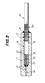
- a glass tube 18 having an outer diameter larger than the inner diameter of the small bore portion 14 and also the coated optical fiber 12 is inserted in the large bore portion 16 of the sleeve 11.
- the bare fiber 13 of the optical fiber 12 is extended through a bore 19 of the glass tube 18 and the small bore portion 14 and terminated at the end face of the sleeve and the end face of the coating 15 is abutted to the end face of the glass tube 18.
- the coated optical fiber 12 has a rough surface portion 20 formed in a surface portion of the coating 15 opposing to the groove 17 formed in the large bore portion 16 of the sleeve and adjacent to the end of the large bore portion 16 of the sleeve.
- the rough surface portion 20 has a roughness corresponding to a lapping film #150 (grain size of 100 f..lm) and a roughing direction crossing perpendicularly the longitudinal direction of the optical fiber 12.
- the sleeve 11, the glass tube 18 and the bare fiber 13 and the coating 15 of the optical fiber 12 are fixed to each other by adhesive 21 which is filled between these components.
- the end portion having the large bore portion 16 of the sleeve 11 and the coating 15 having the rough surface portion 20 are also adhered to each other by the adhesive 21.
- the glass tube 18 is inserted in the sleeve 11 and then the optical fiber 12 is inserted through the sleeve 11 and the glass tube 18 such that the bare fiber 13 is slightly protruded from the end face of the sleeve 11 through the small bore portion 14.
- the nylon coated optical fiber 12 is preliminarily formed with the rough surface portion 20 in the nylon coating 15 and the nylon coating and a primary at the tip portion of the optical fiber are removed to provide the bare fiber 13.
- the adhesive 21 for example heat-curing epoxy adhesive which has been compounded and then deaerated in a vacuum, is sucked into the sleeve 11 to fill spaces or gaps between the components and the inner surface of the sleeve 11 and between the end portion of the large bore portion 16 of the sleeve and the coating 15 having the rough surface portion 20 with the adhesive.
- the adhesive 21 is dried at 80°C for sixty minutes to be cured. Finally, the bare fiber 13 protruded from the small bore portion 14 is cut at the end face of the sleeve and then the end faces of the sleeve and the bare fiber in the small bore portion 14 is polished to provide the optical ferrule.
- the optical ferrules according to the embodiment shown in Fig.3 of the invention and optical ferrules prepared as comparative examples are tested to evaluate separation states at adhered portions after a heat cycle test and under a load of 1.5 kg at -25°C.
- the test results are shown in the following Table.
- the comparative example 1 has a construction as shown in Fig. 1, but includes a coated optical fiber formed with a rough surface portion 20 having a roughing direction parallel to the longitudinal direction of the optical fiber 12, the comparative example 2 has the construction as shown in Fig. 1, but has no rough surface portion 20, and the comparative example 3 has the same construction as shown in Fig. 2.
- the heat cycle A performs one cycle by keeping the ferrule at a normal temperature for ten minutes, at 85°C for thirty minutes, at a normal temperature for ten minutes, and at -40°C for thirty minutes.
- the heat cycle B performs one cycle by keeping the ferrule at a normal temperature for ten minutes, at 80°C for thirty minutes, at a normal temperature for ten minutes and at -25°C for thirty minutes.
- the present invention is not limited to the aforementioned embodiment, but it is possible to made various modifications and variations in the arrangement.
- the rough surface portion 20 of the coating 15 can perform the similar effect as mentioned above by crossing the roughing direction of the rough surface portion and the longitudinal direction of the optical fiber in an angle to each other, except for extending the roughing direction in parallel to the longitudinal direction of the optical fiber.
- the adhesion force between the optical fiber and the sleeve is increased by forming the groove in the inner surface of the sleeve to be adhered to the coating of the coated optical fiber and forming the rough surface in the coating portion opposing to the groove. Furthermore, the glass tube inserted in the sleeve can effectively prevent from separating of the adhered portions, protruding and withdrawing of the bare fiber from the end surface of the sleeve, breaking down of the optical fiber, and separating of the optical fiber from the sleeve due to expansion and shrinkage of the optical fiber caused by temperature variation,
- the ferrule of the invention since the ferrule has no metallic component, measurement accuracy is not deteriorated in case of application for optical electromagnetic measuring instruments, and also the deterioration of durability owing to corrosion is not occurred. Therefore, the ferrule of the invention is superior in reliability and durability and can be always used in stable condition.
Landscapes
- Physics & Mathematics (AREA)
- General Physics & Mathematics (AREA)
- Optics & Photonics (AREA)
- Mechanical Coupling Of Light Guides (AREA)
Applications Claiming Priority (2)
| Application Number | Priority Date | Filing Date | Title |
|---|---|---|---|
| JP1991023346U JP2500523Y2 (ja) | 1991-03-18 | 1991-03-18 | 光学用フェル―ル |
| JP23346/91 | 1991-03-18 |
Publications (2)
| Publication Number | Publication Date |
|---|---|
| EP0505149A2 true EP0505149A2 (de) | 1992-09-23 |
| EP0505149A3 EP0505149A3 (en) | 1993-11-18 |
Family
ID=12108028
Family Applications (1)
| Application Number | Title | Priority Date | Filing Date |
|---|---|---|---|
| EP19920302292 Withdrawn EP0505149A3 (en) | 1991-03-18 | 1992-03-17 | Optical ferrule |
Country Status (6)
| Country | Link |
|---|---|
| US (1) | US5187762A (de) |
| EP (1) | EP0505149A3 (de) |
| JP (1) | JP2500523Y2 (de) |
| KR (1) | KR920018499A (de) |
| AU (1) | AU640558B2 (de) |
| CA (1) | CA2063187C (de) |
Cited By (2)
| Publication number | Priority date | Publication date | Assignee | Title |
|---|---|---|---|---|
| EP0716322A1 (de) * | 1994-12-05 | 1996-06-12 | Asahi Kohden Co., Ltd. | Faseroptischer Halter |
| EP1281993A3 (de) * | 2001-07-30 | 2004-07-14 | SEIKOH GIKEN Co., Ltd. | Faseroptische Steckerstiftanordnung und deren Verwendung in optischem Modul und Stecker |
Families Citing this family (7)
| Publication number | Priority date | Publication date | Assignee | Title |
|---|---|---|---|---|
| JPH08110438A (ja) * | 1994-10-07 | 1996-04-30 | Seiko Giken:Kk | 光ファイバ組立体 |
| JP3363333B2 (ja) * | 1996-11-28 | 2003-01-08 | 京セラ株式会社 | 光ファイバー固定具 |
| CN1196002C (zh) * | 2000-07-31 | 2005-04-06 | 日本电气硝子株式会社 | 带光纤的光装置零件的预备材料,光纤短截棒及制造方法 |
| DE10150813A1 (de) * | 2001-10-15 | 2003-05-15 | Delphi Tech Inc | Optisches Bauteil |
| US8326103B2 (en) * | 2008-04-04 | 2012-12-04 | Baker Hughes Incorporated | Cable and method |
| CN101587212A (zh) * | 2008-05-19 | 2009-11-25 | 鸿富锦精密工业(深圳)有限公司 | 套筒及采用该套筒的光纤连接器插座 |
| GB201506132D0 (en) * | 2015-04-10 | 2015-05-27 | Ge Healthcare Bio Sciences Ab | Device for holding a light guide, and method for manufacturing such a device |
Family Cites Families (14)
| Publication number | Priority date | Publication date | Assignee | Title |
|---|---|---|---|---|
| JPS5674210A (en) * | 1979-11-21 | 1981-06-19 | Nec Corp | Optical fiber connector |
| US4447121A (en) * | 1981-11-06 | 1984-05-08 | Amp Incorporated | Connector for fiber optic member |
| US4673242A (en) * | 1981-12-21 | 1987-06-16 | Thomas & Betts Corporation | Movable closure for optical elements |
| JPS59160110A (ja) * | 1983-03-02 | 1984-09-10 | Fujitsu Ltd | 光コネクタの端末部形成方法 |
| JPS60186813A (ja) * | 1984-03-06 | 1985-09-24 | Toyota Motor Corp | 光コネクタ |
| JPS62258410A (ja) * | 1986-05-02 | 1987-11-10 | Nec Corp | 光コネクタ用プラグハウジング |
| US4743084A (en) * | 1986-05-14 | 1988-05-10 | Amp Incorporated | Optical fiber connector for field application |
| JP2644733B2 (ja) * | 1986-09-19 | 1997-08-25 | 株式会社日立製作所 | 光ファイバジャケット |
| US4875754A (en) * | 1987-08-28 | 1989-10-24 | Minnesota Mining And Manufacturing Company | Optical fiber connector |
| IT1222901B (it) * | 1987-10-14 | 1990-09-12 | Pirelli Cavi Spa | Connettore per fibre ottiche e metodo per posizionare assialmente una fibra ottica nel connettore |
| US4848870A (en) * | 1988-04-06 | 1989-07-18 | Raychem Corporation | Optical fiber jaw connector |
| DE3843946A1 (de) * | 1988-12-24 | 1990-06-28 | Philips Patentverwaltung | Einen lwl koaxial aufnehmender steckerstift und verfahren zu seiner herstellung |
| FR2664711B1 (fr) * | 1990-07-11 | 1993-07-16 | Filotex Sa | Procede de jonction d'un cable optique a tube de protection de fibre a une fiche ou epissure de raccordement. |
| US5080460A (en) * | 1991-02-25 | 1992-01-14 | Amp Incorporated | Crimp and cleave assembly of an optical connector and method of making same |
-
1991
- 1991-03-18 JP JP1991023346U patent/JP2500523Y2/ja not_active Expired - Fee Related
-
1992
- 1992-03-11 US US07/849,342 patent/US5187762A/en not_active Expired - Lifetime
- 1992-03-12 AU AU12864/92A patent/AU640558B2/en not_active Ceased
- 1992-03-17 CA CA002063187A patent/CA2063187C/en not_active Expired - Fee Related
- 1992-03-17 EP EP19920302292 patent/EP0505149A3/en not_active Withdrawn
- 1992-03-18 KR KR1019920004469A patent/KR920018499A/ko not_active Ceased
Cited By (3)
| Publication number | Priority date | Publication date | Assignee | Title |
|---|---|---|---|---|
| EP0716322A1 (de) * | 1994-12-05 | 1996-06-12 | Asahi Kohden Co., Ltd. | Faseroptischer Halter |
| US5644672A (en) * | 1994-12-05 | 1997-07-01 | Asahi Kohoen, Co., Ltd. | Optical fiber holder used in optical connectors |
| EP1281993A3 (de) * | 2001-07-30 | 2004-07-14 | SEIKOH GIKEN Co., Ltd. | Faseroptische Steckerstiftanordnung und deren Verwendung in optischem Modul und Stecker |
Also Published As
| Publication number | Publication date |
|---|---|
| EP0505149A3 (en) | 1993-11-18 |
| US5187762A (en) | 1993-02-16 |
| AU640558B2 (en) | 1993-08-26 |
| KR920018499A (ko) | 1992-10-22 |
| CA2063187C (en) | 1996-12-31 |
| CA2063187A1 (en) | 1992-09-19 |
| JP2500523Y2 (ja) | 1996-06-05 |
| AU1286492A (en) | 1992-10-08 |
| JPH04112205U (ja) | 1992-09-30 |
Similar Documents
| Publication | Publication Date | Title |
|---|---|---|
| US6883976B2 (en) | Optical fiber ferrule assembly and optical module and optical connector using the same | |
| US5187762A (en) | Optical ferrule | |
| US5140661A (en) | Optical fiber terminus | |
| EP0023114B2 (de) | Mit einer Linse ausgerüstete Verbindungen für optische Faser | |
| US4930859A (en) | Fiber optic splice assembly | |
| WO1990007137A1 (fr) | Ferrure de connexion de fibres optiques et connecteur optique l'utilisant | |
| US20020085826A1 (en) | Fiber array, method for fabricating the same and optical device using the fiber array | |
| JP2009086168A (ja) | 割スリーブならびにこれを用いた光レセプタクル及び光アダプタ | |
| JP2551407B2 (ja) | 光フアイバ−コネクタ | |
| JPH0968627A (ja) | 光コネクタ | |
| JPH1062653A (ja) | 多芯フェルール | |
| JP2003043313A (ja) | 光レセプタクル及びそれを用いた光モジュール | |
| JPH03107807A (ja) | 光コネクタレセプタクル | |
| JPH1090555A (ja) | 光コネクタ | |
| JP2005099748A (ja) | 光レセプタクル | |
| JPH0815547A (ja) | 光ファイバ端末回転用ステージ | |
| US20250164293A1 (en) | Radiused sensors for measuring pressure and temperature | |
| JPH02111905A (ja) | 光コネクタ端末構造 | |
| EP0266523B1 (de) | Faseroptische Spleissung | |
| JP3793552B2 (ja) | 光ファイバ固定具およびこれを用いた光ファイバコネクタ | |
| JP2003222763A (ja) | 光レセプタクルとその製造方法及びそれを用いた光モジュール | |
| JP3266514B2 (ja) | 光ファイバーコネクタ | |
| JPH08110438A (ja) | 光ファイバ組立体 | |
| JP2002350693A (ja) | 光レセプタクルとこれを用いた光モジュール | |
| JP2005134552A (ja) | 光ファイバー固定具 |
Legal Events
| Date | Code | Title | Description |
|---|---|---|---|
| PUAI | Public reference made under article 153(3) epc to a published international application that has entered the european phase |
Free format text: ORIGINAL CODE: 0009012 |
|
| AK | Designated contracting states |
Kind code of ref document: A2 Designated state(s): DE FR GB |
|
| PUAL | Search report despatched |
Free format text: ORIGINAL CODE: 0009013 |
|
| AK | Designated contracting states |
Kind code of ref document: A3 Designated state(s): DE FR GB |
|
| 17P | Request for examination filed |
Effective date: 19940506 |
|
| 17Q | First examination report despatched |
Effective date: 19960205 |
|
| STAA | Information on the status of an ep patent application or granted ep patent |
Free format text: STATUS: THE APPLICATION IS DEEMED TO BE WITHDRAWN |
|
| 18D | Application deemed to be withdrawn |
Effective date: 19960817 |