EP0506575A1 - Universale Richt- und Biegemaschine für Bewehrungen aus Betonstahl - Google Patents
Universale Richt- und Biegemaschine für Bewehrungen aus Betonstahl Download PDFInfo
- Publication number
- EP0506575A1 EP0506575A1 EP92400859A EP92400859A EP0506575A1 EP 0506575 A1 EP0506575 A1 EP 0506575A1 EP 92400859 A EP92400859 A EP 92400859A EP 92400859 A EP92400859 A EP 92400859A EP 0506575 A1 EP0506575 A1 EP 0506575A1
- Authority
- EP
- European Patent Office
- Prior art keywords
- concrete
- folding
- chute
- mandrel
- sectioner
- Prior art date
- Legal status (The legal status is an assumption and is not a legal conclusion. Google has not performed a legal analysis and makes no representation as to the accuracy of the status listed.)
- Withdrawn
Links
- 238000005452 bending Methods 0.000 title claims abstract description 9
- 230000002787 reinforcement Effects 0.000 title claims abstract description 8
- 239000004567 concrete Substances 0.000 title claims description 62
- 230000003014 reinforcing effect Effects 0.000 claims abstract description 11
- 238000000034 method Methods 0.000 claims abstract description 7
- 238000004519 manufacturing process Methods 0.000 claims description 5
- 239000011150 reinforced concrete Substances 0.000 claims description 5
- XEEYBQQBJWHFJM-UHFFFAOYSA-N Iron Chemical compound [Fe] XEEYBQQBJWHFJM-UHFFFAOYSA-N 0.000 claims 2
- 229910052742 iron Inorganic materials 0.000 claims 1
- 238000010008 shearing Methods 0.000 description 3
- 229910000831 Steel Inorganic materials 0.000 description 1
- 238000009432 framing Methods 0.000 description 1
- 238000012986 modification Methods 0.000 description 1
- 230000004048 modification Effects 0.000 description 1
- 239000010959 steel Substances 0.000 description 1
Images

Classifications
-
- B—PERFORMING OPERATIONS; TRANSPORTING
- B21—MECHANICAL METAL-WORKING WITHOUT ESSENTIALLY REMOVING MATERIAL; PUNCHING METAL
- B21D—WORKING OR PROCESSING OF SHEET METAL OR METAL TUBES, RODS OR PROFILES WITHOUT ESSENTIALLY REMOVING MATERIAL; PUNCHING METAL
- B21D11/00—Bending not restricted to forms of material mentioned in only one of groups B21D5/00, B21D7/00, B21D9/00; Bending not provided for in groups B21D5/00 - B21D9/00; Twisting
- B21D11/10—Bending specially adapted to produce specific articles, e.g. leaf springs
- B21D11/12—Bending specially adapted to produce specific articles, e.g. leaf springs the articles being reinforcements for concrete
Definitions
- the present invention relates to a folding-sectioning machine for producing in particular concrete rod frames and to a universal straightening-forming machine using this folding-sectioning machine to produce reinforcing bars in concrete and to the use of the latter for the manufacture of armatures.
- reinforced concrete structures require reinforcements of very varied shape and size which are most often formed by longitudinal elements folded in pins at their ends and connected together by frames also made of wire. folded steel.
- the longitudinal elements are produced using a straightening machine which sends a predetermined length of wire into a chute which pours it onto a folding table which folds the ends of the elongated elements into pins.
- the frames are produced using another machine called a framing machine which comprises at least one folding head fed by a straightening machine.
- the object of the present invention is to produce a folding-sectioning machine which makes it possible to cut the concrete ring in the immediate vicinity of its last bend without having to communicate it back and forth movements.
- the present invention also aims to produce a single machine which, by the combination of its various elements, makes it possible to produce both the longitudinal elements of the frames and the frames which join them.
- the subject of the present invention is a folding-sectioning machine for making reinforcing frames in concrete rounds, of the type in which a finger provided with a roller pivots by an adjustable angle around a circular mandrel to bend the round to concrete around the latter, characterized. by the fact that it further comprises a shear, one of the blades of which is located in a recess of the circular mandrel, said recess being located near the point where the concrete rod comes into contact with the mandrel at the start of the bending process.
- the movable blade of the shears is advantageously located in the recess of the mandrel when the latter has a sufficient size. Otherwise, it is advantageous to secure the fixed blade of the shears with the circular mandrel which thus collects the shearing forces produced by the movable blade which is located on the other side of the concrete rod.
- the present invention also relates to a dressing-forming machine for concrete bars, characterized in that it comprises in combination: a dressing machine supplied by at least one reel of concrete bars; a chute intended to receive a section of concrete rod of predetermined length previously erected; a folding table arranged below the chute, table which comprises a folder-sectioner according to the invention of the type described above arranged in a movable manner along the chute and located on the side opposite to the straightener and a folding head possibly capable of being moved along the chute between the folder-sectioner and the straightener; a device making it possible to move the dressing machine between a high position where it sends the standing concrete block into the chute and a low position where it sends the standing concrete block on the folding-sectioner; and a shears placed between the chute and the exit of the straightener when the latter is in the high position.
- the straightening-forming machine first of all makes it possible to produce the longitudinal elements of the reinforced concrete reinforcements by sending into the chute, a section of standing concrete block of predetermined length, after which this section falls on the folding table. whose folding head and folding-sectioner which are placed in the vicinity of the ends of the section of the concrete reinforcing bar ensure the folding of the ends of the latter and the production of pins.
- the dressing-forming machine according to the invention also makes it possible to easily produce frames even of small dimensions, thanks to the fact that the folding-sectioner which is in the vicinity of the dressing unit makes it possible to cut the concrete rod in the vicinity of the last bending without having to communicate back and forth.
- a universal machine is thus obtained, at a lower cost, which makes it possible to produce all types of reinforcement.
- the invention also relates to the methods of using the straightening-forming machine defined above.
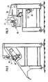
- Figure 1 There is schematically shown in Figure 1 a first embodiment of a folder-sectioner according to the invention.
- This folder-sectioner comprises in the known manner a circular folding mandrel 1 as well as a folding finger 2 which is provided at its end with a roller 3 and which can be pivoted around the axis of the mandrel 1.
- the mandrel 1 has a recess 5 in the vicinity of point 6 where the concrete rod 4 comes into contact with it at the start of the bending process.
- This recess is intended to receive the blade 7 of a shear, the other blade 8 of which is disposed on the other side of the concrete ring 4.
- the two blades 6 and 7 of the shears can be actuated independently of the mandrel 1 which does not undergo in consequence none of the efforts due to shearing.
- the blade 7 can advantageously be moved relative to the blade 8.
- FIG. 2 shows a second embodiment of the folder-cutter according to the invention which corresponds to bending on a mandrel 1 of smaller diameter.
- FIG. 2 shows the folding finger 2 as well as its roller 3 and the concrete ring 4.
- the fixed blade 7 of the shears is integral with the mandrel 1
- the movable blade 8 sections the concrete rod 4 which rests on the blade 7, which is supported by the mandrel 1 which is integral of the machine frame.
- the concrete ring 4 can be sectioned at a point very close to point 6 which is the one from which the concrete ring 4 begins to be folded back on itself.
- the recess 5 in which the blade 7 of the shears is located can occupy less than a quarter of a circle, which makes it possible to produce bends at more than 270 °, and which is greater than what has been need in practice.
- the shearing force between the two blades 7 and 8 is carried out in the known manner, for example using a hydraulic or pneumatic cylinder.
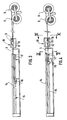
- a dresser-forming machine which comprises a dressing machine 10 provided with feed rollers 11 for pushing the concrete rod 4 coming from the coils 9 between dressing rollers 12 and 13 arranged in planes perpendicular.
- the concrete ring 4 which is erected when it enters the forming machine.
- the latter comprises a chute 14 disposed above a folding table 15 which comprises on the one hand a folder-sectioner 16 according to the invention of the type shown in Figures 1 and 2 and d on the other hand a folding head 17.
- a folding table 15 which comprises on the one hand a folder-sectioner 16 according to the invention of the type shown in Figures 1 and 2 and d on the other hand a folding head 17.
- These two members 16 and 17 can be positioned anywhere along the entire length of the folding table 15.
- the folding-sectioning machine 16 is advantageously arranged on the folding table 15 opposite the folding head 17.
- the folding head 17 can be held in a fixed position.
- FIG. 5 shows on a larger scale a sectional view along V-V of FIG. 4 where we find the chute 14 which can receive a section of concrete reinforcing bar 4.
- the folding head 17 which is constituted by a mandrel 18 against which comes to bear a concrete ring 4 which is pressed by a movable finger 19 which is provided with a roller not shown and which can be pivoted around the mandrel 18 by a predetermined angle to ensure the folding of the concrete rod 4 around the mandrel.
- FIG. 6 shows a view on a larger scale in section along VI-VI of FIG. 4 the straightener 10 and the drive rollers 11 which receive the concrete ring to be dressed 4.
- the dressing machine 10 is mounted on a support 20 articulated at 21 on the frame of the machine while a jack 22 is articulated at 23 on the frame of the machine and at 24 on the support 20 of the dressing machine.
- the different movements of the different parts of the machine which has just been described can be controlled by a microcomputer, in particular, the lengths of the different sections of concrete reinforcing bars which are cut by the dressing machine, the position of the folding-sectioning machine. and that of the folding head as well as the folding angles of each of them.
- the dresser 10 is placed in the high position using the jack 22. In this position, it sends into the chute 14 a predetermined length of round to standing concrete which is sectioned conventionally for example using a shear not shown.
- the chute 14 pours the section of concrete rod 4 erected on the folding table 15, the folding-disconnector 16 and the folding head 17 have been previously brought into positions. which depend on the length of the section of concrete rod 4. It then suffices that the folding-sectioner 16 and the folding head 17 fold the two ends of the concrete rod to obtain the longitudinal element.
- the folder-cutter shears are not used on this occasion.
- the dresser 10 is brought into the low position by acting on the jack 22 while the folder-sectioner 16 is brought to the right.
- the dressing machine 10 then sends the length of the concrete block 4 to the folding-sectioning machine 16 such that the latter exceeds the bending machine 16 sufficiently to produce a hook which is obtained by pivoting the folding roller 3 (fig 1 and 2).
- the straightener 10 then advances the concrete ring 4 by a length corresponding to one side of the frame, then the folding roller 3 folds the concrete ring 4 and so on until the different sides of the frame are formed.
- the concrete ring 4 is advanced as a function of the length of the pin which it is desired to obtain and by actuating the blades 7,8 of the shears to cut the concrete round, the frame of the dresser.
- the invention makes it possible, in a simple way, to produce an efficient universal machine which can produce all the parts necessary for obtaining reinforcements for reinforced concrete.
- the folding head 17 can be fixed to a fixed post.
Landscapes
- Engineering & Computer Science (AREA)
- Mechanical Engineering (AREA)
- Bending Of Plates, Rods, And Pipes (AREA)
Applications Claiming Priority (2)
| Application Number | Priority Date | Filing Date | Title |
|---|---|---|---|
| FR9103711 | 1991-03-27 | ||
| FR9103711A FR2674558A1 (fr) | 1991-03-27 | 1991-03-27 | Dresseuse-formeuse universelle pour armatures en ronds a beton. |
Publications (1)
| Publication Number | Publication Date |
|---|---|
| EP0506575A1 true EP0506575A1 (de) | 1992-09-30 |
Family
ID=9411186
Family Applications (1)
| Application Number | Title | Priority Date | Filing Date |
|---|---|---|---|
| EP92400859A Withdrawn EP0506575A1 (de) | 1991-03-27 | 1992-03-27 | Universale Richt- und Biegemaschine für Bewehrungen aus Betonstahl |
Country Status (2)
| Country | Link |
|---|---|
| EP (1) | EP0506575A1 (de) |
| FR (1) | FR2674558A1 (de) |
Cited By (7)
| Publication number | Priority date | Publication date | Assignee | Title |
|---|---|---|---|---|
| US5878615A (en) * | 1996-06-17 | 1999-03-09 | Akard & Griffin | Apparatus and method for bending/cutting a workpiece |
| EP1535675A1 (de) * | 2003-11-26 | 2005-06-01 | Galanos S.A. | Maschine zum Richten, Biegen und Abschneiden von Bewehrungsstäben aus Eisen |
| CN106424467A (zh) * | 2016-11-15 | 2017-02-22 | 冯广建 | 一种钢筋弯剪装置 |
| CN109396225A (zh) * | 2018-12-24 | 2019-03-01 | 重庆聚泽福机械有限公司 | 一种布斯成型装置 |
| CN111890546A (zh) * | 2020-08-14 | 2020-11-06 | 芜湖市中天管桩股份有限公司 | 一种管桩钢筋骨架用张拉装置 |
| CN113182968A (zh) * | 2021-05-11 | 2021-07-30 | 刘春燕 | 一种铝合金型材加工系统 |
| IT202000013174A1 (it) * | 2020-06-04 | 2021-12-04 | M E P Macch Elettroniche Piegatrici Spa | Apparato e metodo per la lavorazione di prodotti metallici oblunghi |
Citations (5)
| Publication number | Priority date | Publication date | Assignee | Title |
|---|---|---|---|---|
| DE1094076B (de) * | 1959-03-24 | 1960-12-01 | Peddinghaus Paul Ferd Fa | Formkoerper fuer Betoneisen-biegemaschinen |
| FR2126139A2 (de) * | 1971-02-26 | 1972-10-06 | Del Fabro Reningio | |
| FR2310169A1 (fr) * | 1975-05-06 | 1976-12-03 | Evg Entwicklung Verwert Ges | Cintreuse pour materiel en barre, en particulier pour tige d'armature a beton |
| EP0092462A1 (de) * | 1982-04-21 | 1983-10-26 | Profer | Herstellungs- und Transportvorrichtung von bearbeiteten Drahtstücken |
| FR2553314A1 (fr) * | 1983-10-12 | 1985-04-19 | Piegatrici Macch Elettr | Methode et machine de fabrication d'etriers |
-
1991
- 1991-03-27 FR FR9103711A patent/FR2674558A1/fr not_active Withdrawn
-
1992
- 1992-03-27 EP EP92400859A patent/EP0506575A1/de not_active Withdrawn
Patent Citations (5)
| Publication number | Priority date | Publication date | Assignee | Title |
|---|---|---|---|---|
| DE1094076B (de) * | 1959-03-24 | 1960-12-01 | Peddinghaus Paul Ferd Fa | Formkoerper fuer Betoneisen-biegemaschinen |
| FR2126139A2 (de) * | 1971-02-26 | 1972-10-06 | Del Fabro Reningio | |
| FR2310169A1 (fr) * | 1975-05-06 | 1976-12-03 | Evg Entwicklung Verwert Ges | Cintreuse pour materiel en barre, en particulier pour tige d'armature a beton |
| EP0092462A1 (de) * | 1982-04-21 | 1983-10-26 | Profer | Herstellungs- und Transportvorrichtung von bearbeiteten Drahtstücken |
| FR2553314A1 (fr) * | 1983-10-12 | 1985-04-19 | Piegatrici Macch Elettr | Methode et machine de fabrication d'etriers |
Cited By (12)
| Publication number | Priority date | Publication date | Assignee | Title |
|---|---|---|---|---|
| US5878615A (en) * | 1996-06-17 | 1999-03-09 | Akard & Griffin | Apparatus and method for bending/cutting a workpiece |
| EP1535675A1 (de) * | 2003-11-26 | 2005-06-01 | Galanos S.A. | Maschine zum Richten, Biegen und Abschneiden von Bewehrungsstäben aus Eisen |
| CN106424467A (zh) * | 2016-11-15 | 2017-02-22 | 冯广建 | 一种钢筋弯剪装置 |
| CN106424467B (zh) * | 2016-11-15 | 2018-07-03 | 冯广建 | 一种钢筋弯剪装置 |
| CN109396225A (zh) * | 2018-12-24 | 2019-03-01 | 重庆聚泽福机械有限公司 | 一种布斯成型装置 |
| IT202000013174A1 (it) * | 2020-06-04 | 2021-12-04 | M E P Macch Elettroniche Piegatrici Spa | Apparato e metodo per la lavorazione di prodotti metallici oblunghi |
| WO2021245715A1 (en) * | 2020-06-04 | 2021-12-09 | M.E.P. Macchine Elettroniche Piegatrici S.P.A. | Apparatus and method for working oblong metal products |
| CN115702050A (zh) * | 2020-06-04 | 2023-02-14 | Mep意大利美普机械制造有限公司 | 用于加工长形金属产品的设备和方法 |
| US12337367B2 (en) | 2020-06-04 | 2025-06-24 | M.E.P. Macchine Elettroniche Piegatrici S.P.A. | Apparatus and method for working oblong metal products |
| CN111890546A (zh) * | 2020-08-14 | 2020-11-06 | 芜湖市中天管桩股份有限公司 | 一种管桩钢筋骨架用张拉装置 |
| CN113182968A (zh) * | 2021-05-11 | 2021-07-30 | 刘春燕 | 一种铝合金型材加工系统 |
| CN113182968B (zh) * | 2021-05-11 | 2022-12-16 | 浙江拓卡斯科技股份有限公司 | 一种铝合金型材加工系统 |
Also Published As
| Publication number | Publication date |
|---|---|
| FR2674558A1 (fr) | 1992-10-02 |
Similar Documents
| Publication | Publication Date | Title |
|---|---|---|
| EP0168334A1 (de) | Schneidvorrichtung für Rohre aus Papier und sonstigen Materialien | |
| FR2719513A1 (fr) | Outil de coupe d'un profilé notamment une gouttière. | |
| FR2747328A1 (fr) | Machine a cintrer ou a cambrer un profile, et tete de cintrage pour une telle machine | |
| CH648890A5 (fr) | Machine portative pour realiser automatiquement les ligatures sur des armatures, notamment de beton arme, et procede de mise en action. | |
| FR2577594A1 (fr) | Dispositif d'attache de barres d'armature | |
| FR2674558A1 (fr) | Dresseuse-formeuse universelle pour armatures en ronds a beton. | |
| FR2460203A1 (fr) | Machine pour la production de corps coniques de receptacles comportant un epaulement de fond annulaire interieur | |
| FR2476044A1 (fr) | Dispositif de sectionnement pour bandes enroulees sur des mandrins montes sur des rouleaux porteurs entraines en rotation | |
| EP0305230A1 (de) | Periodische Papierbahnzufuhr einer Maschine, insbesondere für eine blattabschneidende Presse | |
| EP1037800A1 (de) | Vorrichtung zum anbringen von aus einem kontinuierlichen schlauch hergestellten, wärmeschrumpfbaren hülsen auf gegenständen | |
| EP0435769A1 (de) | Verfahren und automatische Vorrichtung zur Herstellung einer Stahlbewehrung und mit diesem Verfahren hergestellte Stahlbewehrung | |
| EP2516146B1 (de) | Verfahren und vorrichtung zur messung des lagenwinkels vor einem schneidvorgang | |
| FR2602160A1 (fr) | Procede et machine modulaire de cambrage de fils metalliques | |
| FR2772652A1 (fr) | Procede et dispositif de formage de fils metalliques | |
| FR2715334A1 (fr) | Machine pour cintrer un matériau se présentant sous une forme sensiblement rectiligne. | |
| EP1972562B1 (de) | Verfahren zur Befestigung eines Kunststoffgriffs auf einer metallischen Verpackung | |
| FR2787097A1 (fr) | Procede et dispositif pour enrouler une bande de matiere amenee en continu | |
| CH619163A5 (de) | ||
| EP0109905B1 (de) | Vorrichtung zum Biegen von Rohren | |
| EP0220095A1 (de) | Verfahren und Vorrichtung zum Ausrichten und Anpassen eines ersten Teiles aus Kunststoff, das beispielsweise thermoverschweissbar mit einem zweiten ähnlichen Kunststoffteil ist, welches ebenfalls im Hinblick auf das Verbinden der Enden ausgerichtet werden kann | |
| FR2604386A1 (fr) | Procede d'avance automatique d'un chariot d'une coupeuse a un couteau, et dispositif pour la mise en oeuvre de ce procede | |
| FR2758281A1 (fr) | Machine a cintrer des tubes de faible diametre, notamment inferieurs a 10mm, predecoupes et presentant des systemes de raccord a chacune de leurs extremites, et tete de cintrage pour une telle machine | |
| EP0787546A1 (de) | Vorrichtung zum Vorfalzen und Falzen eines Bleches | |
| FR2622129A1 (fr) | Machine de conformation d'un troncon de fil ou de tube par pliages successifs | |
| FR2856615A1 (fr) | Dispositif de cintrage de profiles, notamment pour la realisation de portails |
Legal Events
| Date | Code | Title | Description |
|---|---|---|---|
| PUAI | Public reference made under article 153(3) epc to a published international application that has entered the european phase |
Free format text: ORIGINAL CODE: 0009012 |
|
| AK | Designated contracting states |
Kind code of ref document: A1 Designated state(s): AT BE CH DE DK ES GB GR IT LI |
|
| 17P | Request for examination filed |
Effective date: 19930329 |
|
| 17Q | First examination report despatched |
Effective date: 19941102 |
|
| STAA | Information on the status of an ep patent application or granted ep patent |
Free format text: STATUS: THE APPLICATION IS DEEMED TO BE WITHDRAWN |
|
| 18D | Application deemed to be withdrawn |
Effective date: 19941002 |