EP0506596A1 - Installation pour la coulée en motte - Google Patents
Installation pour la coulée en motte Download PDFInfo
- Publication number
- EP0506596A1 EP0506596A1 EP92500028A EP92500028A EP0506596A1 EP 0506596 A1 EP0506596 A1 EP 0506596A1 EP 92500028 A EP92500028 A EP 92500028A EP 92500028 A EP92500028 A EP 92500028A EP 0506596 A1 EP0506596 A1 EP 0506596A1
- Authority
- EP
- European Patent Office
- Prior art keywords
- moulding
- boxes
- motes
- moulds
- striking
- Prior art date
- Legal status (The legal status is an assumption and is not a legal conclusion. Google has not performed a legal analysis and makes no representation as to the accuracy of the status listed.)
- Withdrawn
Links
Images

Classifications
-
- B—PERFORMING OPERATIONS; TRANSPORTING
- B22—CASTING; POWDER METALLURGY
- B22D—CASTING OF METALS; CASTING OF OTHER SUBSTANCES BY THE SAME PROCESSES OR DEVICES
- B22D47/00—Casting plants
- B22D47/02—Casting plants for both moulding and casting
Definitions
- the present invention relates to an installation used in moulding foundry motes, incorporating improvements designed to substantially reduce the costs in such installations, without impairing the performance or operating characteristics thereof.
- the sand mould remains at all times inside a metallic box, namely a moulding box, where the entire processing operation is effected, in other words producing the sand mould, striking, cores placement, casting, cooling, and so forth.
- the improvements subject of the invention fully solve the above problems, presenting a hybrid solution which initially uses air impact moulding machines of a rather low cost, above all as compared with the cost of a mote manufacturing machine, which air impact moulding machine is obviously provided with moulding boxes, but singular in that the said moulding boxes are used only at the pressing, striking, flattening, cores placement, tipping and closing stations, after which the mould continues to travel along the rest of the installation freely, that is as a mote, thereby to considerably lower the number of moulding boxes required, which number could even be twenty times smaller than that required for a conventional air impact moulding facililty.
- Figure 1.- Is a diagrammatic plan view of a given practical embodiment of a foundry motes moulding installation constructed in accordance with the improvements subject of the invention.
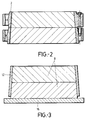
- Figure 2.- Is a diagrammatic side elevation and sectional view of a special motes moulding box required to put the said improvements into effect.
- a foundry motes moulding installation constructed in accordance with the improvements subject of the invention is based upon a machine (1) for moulding sand in metallic boxes (2), as shown in detail in figure 2, which moulding machine can be provided with a rotatory table with two stations, station A where the mould is filled and compacted, and station B where pressing and striking take place, that is, the moulding plate is removed such that the upper and lower half-moulds are already provided with the bas-relief or recessed figure which when placed over one another shall define the ultimate shape of the part to be obtained, the said moulding machines (1) being fitted with fast moulding plates changeover equipment C.
- an apparatus (3) for flattening the face opposite the indent or figure obtained in the mould is provided.
- a unit (2) is provided for tipping and milling the sprue.
- a station (5) is provided for placement of cores, if required, in the lower half-box, which station takes up a small number of moulding boxes (2), in particular four or five.
- a closing unit (6) is then provided, where the boxes are closed or assembled, and thus the mould is closed, specifically when the upper half-mould is placed over the lower half-mould, to which end the box incorporating the upper half-mould, which arrives at the sprue milling operation with the flat portion downwards, is naturally tipped in order that the figures in both half-moulds match and meet one another.
- the installation matches any conventional installation using an air impact moulding machine.
- the installation turns from a casting installation working with boxes to a casting installation working with motes.
- a manipulator removes the sand mould, that is the mote (8) from the moulding box (2) such that the said empty moulding boxes (2) return along the line (9) to the moulding machine (1), a box tipping unit (10) standing in the way back (9), whereas the motes (8) move on to a unit (11) which provides the said motes with sleeves or counterweights (12), shown in detail in figure 3, from which unit the motes move towards the casting ladle (14), through the line (13), where they are provided with the relevant metal batch.
- the line (13) is relatively short, with only four or five spaces, enough for the metal to solidify and for the ferrostatic pressure generated thereby, and which tends to separate both half-moulds making up the mote (8), to disappear, which line (13) ends in a unit (15) which removes the said sleeve (12).
- the motes (8) upon becoming such elements, that is when they leave the moulding boxes (2), are deposited upon pallets (16) and there provided with the sleeves (12), being supported by the same when such sleeves (12) are removed at the stripping unit (15), moving on to the cooling area (16) where they remain for a considerable space of time and which they enter with the assistance of transfer cars (17) mounted upon guides (18) and which are fitted with drivers (19).
- a line (20) is defined wherein a station (21) is provided for the motes to leave laterally towards a striking grate (22) driven by a lateral driver (23), whilst the empty pallets (16) continue to move forward towards a transfer car (24) which moves the same towards the entrance area (25) from which a driver (26) places the same under the manipulator (7) which shall again deposit a mote upon each pallet and in turn eliminate or release the moulding box in which the latter is located, whereupon the installation's working cycle comes to a close, that is whilst the pallet carrying the mote again moves to the line (12) to receive the discharge of the casting ladle (14), the empty moulding box (2) starts on the return path (9) driven by a driver (27).
- the moulding boxes (2) used are special, cup-shaped in order to expedite their disengagement from the mote when activated by the manipulator (7) and that, similarly, the sleeve or counterweight (12) which must keep the mote closed against the metal's ferrostatic pressure, has the same cup shape, as can in turn be observed in figure 3.
Landscapes
- Engineering & Computer Science (AREA)
- Mechanical Engineering (AREA)
- Casting Devices For Molds (AREA)
Applications Claiming Priority (2)
| Application Number | Priority Date | Filing Date | Title |
|---|---|---|---|
| ES9100779A ES2029651A6 (es) | 1991-03-26 | 1991-03-26 | Mejoras en instalaciones de moldeo de motas para fundicion. |
| ES9100779 | 1991-03-26 |
Publications (1)
| Publication Number | Publication Date |
|---|---|
| EP0506596A1 true EP0506596A1 (fr) | 1992-09-30 |
Family
ID=8271824
Family Applications (1)
| Application Number | Title | Priority Date | Filing Date |
|---|---|---|---|
| EP92500028A Withdrawn EP0506596A1 (fr) | 1991-03-26 | 1992-03-25 | Installation pour la coulée en motte |
Country Status (2)
| Country | Link |
|---|---|
| EP (1) | EP0506596A1 (fr) |
| ES (1) | ES2029651A6 (fr) |
Cited By (1)
| Publication number | Priority date | Publication date | Assignee | Title |
|---|---|---|---|---|
| CN105499518A (zh) * | 2016-02-05 | 2016-04-20 | 宁国市志诚机械制造有限公司 | 铸造造型生产线及铸造生产线 |
Citations (4)
| Publication number | Priority date | Publication date | Assignee | Title |
|---|---|---|---|---|
| FR1147675A (fr) * | 1956-04-13 | 1957-11-28 | Procédé et appareil pour la fonderie | |
| US3630268A (en) * | 1969-09-08 | 1971-12-28 | Sherwin Williams Co | Foundry molding machine with means to alternately index cope and drag flasks between molding and closing units |
| DE3241288A1 (de) * | 1982-11-09 | 1984-05-10 | BMD Badische Maschinenfabrik Durlach GmbH, 7500 Karlsruhe | Giesserei-formanlage |
| FR2635702A1 (fr) * | 1988-09-01 | 1990-03-02 | Fischer Ag Georg | Procede et dispositif de moulage |
-
1991
- 1991-03-26 ES ES9100779A patent/ES2029651A6/es not_active Expired - Lifetime
-
1992
- 1992-03-25 EP EP92500028A patent/EP0506596A1/fr not_active Withdrawn
Patent Citations (4)
| Publication number | Priority date | Publication date | Assignee | Title |
|---|---|---|---|---|
| FR1147675A (fr) * | 1956-04-13 | 1957-11-28 | Procédé et appareil pour la fonderie | |
| US3630268A (en) * | 1969-09-08 | 1971-12-28 | Sherwin Williams Co | Foundry molding machine with means to alternately index cope and drag flasks between molding and closing units |
| DE3241288A1 (de) * | 1982-11-09 | 1984-05-10 | BMD Badische Maschinenfabrik Durlach GmbH, 7500 Karlsruhe | Giesserei-formanlage |
| FR2635702A1 (fr) * | 1988-09-01 | 1990-03-02 | Fischer Ag Georg | Procede et dispositif de moulage |
Cited By (1)
| Publication number | Priority date | Publication date | Assignee | Title |
|---|---|---|---|---|
| CN105499518A (zh) * | 2016-02-05 | 2016-04-20 | 宁国市志诚机械制造有限公司 | 铸造造型生产线及铸造生产线 |
Also Published As
| Publication number | Publication date |
|---|---|
| ES2029651A6 (es) | 1992-08-16 |
Similar Documents
| Publication | Publication Date | Title |
|---|---|---|
| BE1007893A7 (nl) | Werkwijze voor het vervaardigen van plastiekvoorwerpen, in het bijzonder van voorvormelingen. | |
| US4592407A (en) | Full automatic die casting machine | |
| CN101293276B (zh) | 铜器件的铸造方法 | |
| CN105798283A (zh) | 一种铸造生产线 | |
| US4982778A (en) | Molding process and apparatus | |
| US3736978A (en) | Mold forming apparatus with flask having opposed shoulder portions | |
| CN119175362A (zh) | 一种消失模铸造生产线 | |
| CA1092782A (fr) | Traduction non-disponible | |
| US4054172A (en) | Device for the production of castings | |
| US5063987A (en) | Apparatus for cooling molds | |
| KR19990051756A (ko) | 알루미늄 휠 주조장치 | |
| CN208583965U (zh) | 一种长铸件的渣包浇口自动去除装置 | |
| EP1326726B1 (fr) | Procede et dispositif de progression pas a pas de moules dans une usine de fonderie a chaine de moules | |
| EP3283248B1 (fr) | Procédé et système pour l'indexation de pièces moulées | |
| GB755048A (en) | Pig casting machine | |
| CN220612287U (zh) | 一种定量浇铸系统 | |
| JPS59107767A (ja) | 生型用鋳造ライン | |
| US5711361A (en) | Method for producing ready-to-use casting shells or core assemblies | |
| WO1991012104A1 (fr) | Methode de moulage a coulee verticale | |
| JPH05177341A (ja) | 精密鋳造設備における製品分離装置 | |
| GB2285950A (en) | Moulding bricks in moulds with movable bottoms | |
| ES2029651A6 (es) | Mejoras en instalaciones de moldeo de motas para fundicion. | |
| JPS5641068A (en) | Knock-out device after casting | |
| SU1044420A2 (ru) | Кокильный станок | |
| CN209754012U (zh) | 一种多腔铸件的自动分选装置 |
Legal Events
| Date | Code | Title | Description |
|---|---|---|---|
| PUAI | Public reference made under article 153(3) epc to a published international application that has entered the european phase |
Free format text: ORIGINAL CODE: 0009012 |
|
| AK | Designated contracting states |
Kind code of ref document: A1 Designated state(s): AT DE FR GB IT |
|
| 17P | Request for examination filed |
Effective date: 19930315 |
|
| 17Q | First examination report despatched |
Effective date: 19950221 |
|
| 18D | Application deemed to be withdrawn |
Effective date: 19950704 |