EP0506879B1 - Procede et appareil d'administration iontophoretique par impulsion de medicaments - Google Patents
Procede et appareil d'administration iontophoretique par impulsion de medicaments Download PDFInfo
- Publication number
- EP0506879B1 EP0506879B1 EP91902909A EP91902909A EP0506879B1 EP 0506879 B1 EP0506879 B1 EP 0506879B1 EP 91902909 A EP91902909 A EP 91902909A EP 91902909 A EP91902909 A EP 91902909A EP 0506879 B1 EP0506879 B1 EP 0506879B1
- Authority
- EP
- European Patent Office
- Prior art keywords
- pulse
- segment
- predetermined
- pulse width
- average current
- Prior art date
- Legal status (The legal status is an assumption and is not a legal conclusion. Google has not performed a legal analysis and makes no representation as to the accuracy of the status listed.)
- Expired - Lifetime
Links
- 238000000034 method Methods 0.000 title claims abstract description 18
- 238000012377 drug delivery Methods 0.000 title description 25
- 229940079593 drug Drugs 0.000 claims abstract description 24
- 239000003814 drug Substances 0.000 claims abstract description 24
- 230000000737 periodic effect Effects 0.000 claims description 17
- 238000002651 drug therapy Methods 0.000 claims description 8
- 230000001225 therapeutic effect Effects 0.000 abstract description 58
- 238000001647 drug administration Methods 0.000 abstract description 2
- 210000003491 skin Anatomy 0.000 description 79
- 230000006870 function Effects 0.000 description 30
- 210000001519 tissue Anatomy 0.000 description 26
- 238000002560 therapeutic procedure Methods 0.000 description 13
- 210000000434 stratum corneum Anatomy 0.000 description 10
- 238000012360 testing method Methods 0.000 description 10
- 206010040880 Skin irritation Diseases 0.000 description 8
- 238000013461 design Methods 0.000 description 8
- 230000036556 skin irritation Effects 0.000 description 8
- 231100000475 skin irritation Toxicity 0.000 description 8
- 239000000126 substance Substances 0.000 description 8
- 230000001276 controlling effect Effects 0.000 description 7
- 239000003990 capacitor Substances 0.000 description 5
- 238000010586 diagram Methods 0.000 description 5
- 230000028161 membrane depolarization Effects 0.000 description 5
- 230000004044 response Effects 0.000 description 5
- 241000282887 Suidae Species 0.000 description 4
- 238000013459 approach Methods 0.000 description 4
- 230000008901 benefit Effects 0.000 description 4
- 230000010287 polarization Effects 0.000 description 4
- QTBSBXVTEAMEQO-UHFFFAOYSA-N Acetic acid Chemical compound CC(O)=O QTBSBXVTEAMEQO-UHFFFAOYSA-N 0.000 description 3
- PEDCQBHIVMGVHV-UHFFFAOYSA-N Glycerine Chemical compound OCC(O)CO PEDCQBHIVMGVHV-UHFFFAOYSA-N 0.000 description 3
- 239000004372 Polyvinyl alcohol Substances 0.000 description 3
- FAPWRFPIFSIZLT-UHFFFAOYSA-M Sodium chloride Chemical compound [Na+].[Cl-] FAPWRFPIFSIZLT-UHFFFAOYSA-M 0.000 description 3
- 230000008878 coupling Effects 0.000 description 3
- 238000010168 coupling process Methods 0.000 description 3
- 238000005859 coupling reaction Methods 0.000 description 3
- 230000000694 effects Effects 0.000 description 3
- 238000009472 formulation Methods 0.000 description 3
- 229920003088 hydroxypropyl methyl cellulose Polymers 0.000 description 3
- 235000010979 hydroxypropyl methyl cellulose Nutrition 0.000 description 3
- 230000037427 ion transport Effects 0.000 description 3
- 150000002500 ions Chemical class 0.000 description 3
- 230000007794 irritation Effects 0.000 description 3
- 239000000203 mixture Substances 0.000 description 3
- 229920002451 polyvinyl alcohol Polymers 0.000 description 3
- XLYOFNOQVPJJNP-UHFFFAOYSA-N water Substances O XLYOFNOQVPJJNP-UHFFFAOYSA-N 0.000 description 3
- DYUTXEVRMPFGTH-UHFFFAOYSA-N 4-(2,5-dimethylphenyl)-5-methyl-1,3-thiazol-2-amine Chemical compound S1C(N)=NC(C=2C(=CC=C(C)C=2)C)=C1C DYUTXEVRMPFGTH-UHFFFAOYSA-N 0.000 description 2
- WCUXLLCKKVVCTQ-UHFFFAOYSA-M Potassium chloride Chemical compound [Cl-].[K+] WCUXLLCKKVVCTQ-UHFFFAOYSA-M 0.000 description 2
- 230000002051 biphasic effect Effects 0.000 description 2
- 230000000052 comparative effect Effects 0.000 description 2
- 229960002738 hydromorphone hydrochloride Drugs 0.000 description 2
- 230000006872 improvement Effects 0.000 description 2
- 238000002347 injection Methods 0.000 description 2
- 239000007924 injection Substances 0.000 description 2
- 230000003993 interaction Effects 0.000 description 2
- 238000007726 management method Methods 0.000 description 2
- 230000007246 mechanism Effects 0.000 description 2
- 230000005012 migration Effects 0.000 description 2
- 238000013508 migration Methods 0.000 description 2
- 230000037361 pathway Effects 0.000 description 2
- 239000008213 purified water Substances 0.000 description 2
- 230000002441 reversible effect Effects 0.000 description 2
- 230000009885 systemic effect Effects 0.000 description 2
- YKFROQCFVXOUPW-UHFFFAOYSA-N 4-(methylthio) aniline Chemical compound CSC1=CC=C(N)C=C1 YKFROQCFVXOUPW-UHFFFAOYSA-N 0.000 description 1
- 208000019901 Anxiety disease Diseases 0.000 description 1
- UXVMQQNJUSDDNG-UHFFFAOYSA-L Calcium chloride Chemical compound [Cl-].[Cl-].[Ca+2] UXVMQQNJUSDDNG-UHFFFAOYSA-L 0.000 description 1
- 206010065929 Cardiovascular insufficiency Diseases 0.000 description 1
- 201000003883 Cystic fibrosis Diseases 0.000 description 1
- 235000016796 Euonymus japonicus Nutrition 0.000 description 1
- 240000006570 Euonymus japonicus Species 0.000 description 1
- KRHYYFGTRYWZRS-UHFFFAOYSA-M Fluoride anion Chemical compound [F-] KRHYYFGTRYWZRS-UHFFFAOYSA-M 0.000 description 1
- 208000002193 Pain Diseases 0.000 description 1
- 229930182555 Penicillin Natural products 0.000 description 1
- JGSARLDLIJGVTE-MBNYWOFBSA-N Penicillin G Chemical compound N([C@H]1[C@H]2SC([C@@H](N2C1=O)C(O)=O)(C)C)C(=O)CC1=CC=CC=C1 JGSARLDLIJGVTE-MBNYWOFBSA-N 0.000 description 1
- 102100026827 Protein associated with UVRAG as autophagy enhancer Human genes 0.000 description 1
- 101710102978 Protein associated with UVRAG as autophagy enhancer Proteins 0.000 description 1
- 229960000583 acetic acid Drugs 0.000 description 1
- 230000009056 active transport Effects 0.000 description 1
- 230000036506 anxiety Effects 0.000 description 1
- 230000033228 biological regulation Effects 0.000 description 1
- 230000000747 cardiac effect Effects 0.000 description 1
- 230000005591 charge neutralization Effects 0.000 description 1
- 238000007796 conventional method Methods 0.000 description 1
- 150000001885 cortisol derivatives Chemical class 0.000 description 1
- 230000002999 depolarising effect Effects 0.000 description 1
- 210000004207 dermis Anatomy 0.000 description 1
- 238000001514 detection method Methods 0.000 description 1
- 229960002344 dexamethasone sodium phosphate Drugs 0.000 description 1
- PLCQGRYPOISRTQ-FCJDYXGNSA-L dexamethasone sodium phosphate Chemical compound [Na+].[Na+].C1CC2=CC(=O)C=C[C@]2(C)[C@]2(F)[C@@H]1[C@@H]1C[C@@H](C)[C@@](C(=O)COP([O-])([O-])=O)(O)[C@@]1(C)C[C@@H]2O PLCQGRYPOISRTQ-FCJDYXGNSA-L 0.000 description 1
- 238000007599 discharging Methods 0.000 description 1
- 230000009977 dual effect Effects 0.000 description 1
- 238000003708 edge detection Methods 0.000 description 1
- 230000005684 electric field Effects 0.000 description 1
- 239000008151 electrolyte solution Substances 0.000 description 1
- 230000007613 environmental effect Effects 0.000 description 1
- 210000002615 epidermis Anatomy 0.000 description 1
- 229940091249 fluoride supplement Drugs 0.000 description 1
- 238000004128 high performance liquid chromatography Methods 0.000 description 1
- 239000001866 hydroxypropyl methyl cellulose Substances 0.000 description 1
- UFVKGYZPFZQRLF-UHFFFAOYSA-N hydroxypropyl methyl cellulose Chemical compound OC1C(O)C(OC)OC(CO)C1OC1C(O)C(O)C(OC2C(C(O)C(OC3C(C(O)C(O)C(CO)O3)O)C(CO)O2)O)C(CO)O1 UFVKGYZPFZQRLF-UHFFFAOYSA-N 0.000 description 1
- 208000015181 infectious disease Diseases 0.000 description 1
- 208000014674 injury Diseases 0.000 description 1
- 239000012212 insulator Substances 0.000 description 1
- 238000001990 intravenous administration Methods 0.000 description 1
- 229960004393 lidocaine hydrochloride Drugs 0.000 description 1
- YECIFGHRMFEPJK-UHFFFAOYSA-N lidocaine hydrochloride monohydrate Chemical compound O.[Cl-].CC[NH+](CC)CC(=O)NC1=C(C)C=CC=C1C YECIFGHRMFEPJK-UHFFFAOYSA-N 0.000 description 1
- 239000000463 material Substances 0.000 description 1
- 238000005259 measurement Methods 0.000 description 1
- 239000012528 membrane Substances 0.000 description 1
- 238000012986 modification Methods 0.000 description 1
- 230000004048 modification Effects 0.000 description 1
- 230000036407 pain Effects 0.000 description 1
- 230000035515 penetration Effects 0.000 description 1
- 229940049954 penicillin Drugs 0.000 description 1
- 230000035699 permeability Effects 0.000 description 1
- 239000006187 pill Substances 0.000 description 1
- 229960001963 pilocarpine nitrate Drugs 0.000 description 1
- 239000001103 potassium chloride Substances 0.000 description 1
- 235000011164 potassium chloride Nutrition 0.000 description 1
- 230000008569 process Effects 0.000 description 1
- 230000009467 reduction Effects 0.000 description 1
- 230000001105 regulatory effect Effects 0.000 description 1
- 238000011160 research Methods 0.000 description 1
- 238000012216 screening Methods 0.000 description 1
- 230000035945 sensitivity Effects 0.000 description 1
- 230000035939 shock Effects 0.000 description 1
- 231100000075 skin burn Toxicity 0.000 description 1
- 239000011780 sodium chloride Substances 0.000 description 1
- 239000000243 solution Substances 0.000 description 1
- 241000894007 species Species 0.000 description 1
- 230000004936 stimulating effect Effects 0.000 description 1
- 229940126585 therapeutic drug Drugs 0.000 description 1
- 230000000699 topical effect Effects 0.000 description 1
- 230000037317 transdermal delivery Effects 0.000 description 1
- 238000012546 transfer Methods 0.000 description 1
- 230000032258 transport Effects 0.000 description 1
- 230000008733 trauma Effects 0.000 description 1
- 238000005303 weighing Methods 0.000 description 1
Images


Classifications
-
- A—HUMAN NECESSITIES
- A61—MEDICAL OR VETERINARY SCIENCE; HYGIENE
- A61N—ELECTROTHERAPY; MAGNETOTHERAPY; RADIATION THERAPY; ULTRASOUND THERAPY
- A61N1/00—Electrotherapy; Circuits therefor
- A61N1/18—Applying electric currents by contact electrodes
- A61N1/20—Applying electric currents by contact electrodes continuous direct currents
- A61N1/30—Apparatus for iontophoresis, i.e. transfer of media in ionic state by an electromotoric force into the body, or cataphoresis
-
- A—HUMAN NECESSITIES
- A61—MEDICAL OR VETERINARY SCIENCE; HYGIENE
- A61N—ELECTROTHERAPY; MAGNETOTHERAPY; RADIATION THERAPY; ULTRASOUND THERAPY
- A61N1/00—Electrotherapy; Circuits therefor
- A61N1/18—Applying electric currents by contact electrodes
- A61N1/32—Applying electric currents by contact electrodes alternating or intermittent currents
- A61N1/325—Applying electric currents by contact electrodes alternating or intermittent currents for iontophoresis, i.e. transfer of media in ionic state by an electromotoric force into the body
-
- A—HUMAN NECESSITIES
- A61—MEDICAL OR VETERINARY SCIENCE; HYGIENE
- A61N—ELECTROTHERAPY; MAGNETOTHERAPY; RADIATION THERAPY; ULTRASOUND THERAPY
- A61N1/00—Electrotherapy; Circuits therefor
- A61N1/02—Details
- A61N1/04—Electrodes
- A61N1/0404—Electrodes for external use
- A61N1/0408—Use-related aspects
- A61N1/0428—Specially adapted for iontophoresis, e.g. AC, DC or including drug reservoirs
- A61N1/0432—Anode and cathode
Definitions
- the present invention in general, relates to the field of iontophoresis.
- the present invention relates to a method and apparatus for transdermal iontophoretic delivery of ionic substances by application of pulsed electrical energy having distinctive, complex waveform characteristics. These waveform characteristics are controlled to provide dual-segment, therapeutic pulses which significantly improve the efficiency of such iontophoretic treatment, without substantially increasing skin irritation.
- Iontophoresis is a process which involves the transport of ionic substances into body tissue, such as through the skin, by the passage of a direct electric current through an electrolyte solution containing the ionic substance to be administered.
- Conventional iontophoretic devices typically include a battery and simple current control circuitry coupled to two electrodes, namely the active and indifferent electrodes.
- the active electrode contains the desired ionic substance to be administered, e.g., a drug in its ionic form having the same charge as the active electrode.
- the indifferent electrode is typically moistened with saline solution or provided with some other ionic conductive medium.
- the indifferent electrode serves as a ground electrode to close the electrical circuit through the body.
- Iontophoresis offers many advantages to other conventional drug delivery regimens, such as oral administration by pills or intravenous administration by needle injection.
- iontophoresis provides a noninvasive procedure with reduced trauma, pain, anxiety and risk of infection.
- Iontophoresis is well-adapted for local or topical treatment, such that high local concentration of the drug administered can be accomplished with a corresponding reduction of unwanted systemic side effects.
- Iontophoresis also offers great flexibility as to the rate of drug administration, regardless of whether the desired therapy is local or systemic, since the rate of drug delivery can be controllably varied by miniaturized programmable circuitry which precisely varies the iontophoretic current applied.
- Iontophoresis has been used, for example, for transdermal delivery of various drugs such as lidocaine hydrochloride, hydrocortisone derivatives, acetic acid, fluoride, penicillin, and dexamethasone sodium phosphate. It has also been used to deliver pilocarpine nitrate as part of a screening procedure for cystic fibrosis.
- drugs such as lidocaine hydrochloride, hydrocortisone derivatives, acetic acid, fluoride, penicillin, and dexamethasone sodium phosphate. It has also been used to deliver pilocarpine nitrate as part of a screening procedure for cystic fibrosis.
- these factors which must be managed include, for example: (a) various electrochemical factors, such as the type, molecular size, weight and ionic concentration of the drug, presence of extraneous ions competing with the charged drug molecules, and pH conditions at the interface of the skin and active electrode; (b) various electronic factors associated with active transport of the charged drug, such as the power source voltage, the type and surface area of the electrodes, use of constant or pulsed DC current, pulse width, and frequency; and (c) various physiological considerations peculiar to treatment of skin tissue, such as its permeability and sensitivity to each particular drug type, as well as the electrical properties of skin tissue. Further complexity arises from the fact that many of these factors can vary from patient to patient, and even as to the same patient as a function of specific body location receiving therapy, duration of therapy or therapeutic drug type.
- Prior art iontophoresis devices provide either a constant DC or a pulsed DC current to drive the electrodes.
- either mode of operation has required a tradeoff between drug delivery efficiency and irritation to the skin being treated.
- the constant DC mode will deliver greater quantities of drug than the pulsed DC mode, primarily due to the constant DC mode's uninterrupted current flow (i.e., the effective duration of current flow, or the effective average current, is greater).
- the constant DC mode there is a constant polarizing current producing a residual charge within the body tissue, which is at least partially depolarized when operating in the pulsed DC mode during the "off" time interval between pulses. Consequently, the constant DC mode tends to produce greater irritation to the skin beneath the electrode than that caused when using the pulsed DC mode.
- US-A-4543956 discloses a cardiac pacer wherein a biphasic waveform is applied to the heart.
- This waveform comprises a relatively short, high amplitude stimulating pulse followed by a compensating pulse of smaller amplitude but longer duration.
- the biphasic waveform provides rapid electrode charge neutralisation and is automatically and dynamically balanced so that the electrical charges of each pulse are equal.
- the present invention is embodied in a method and apparatus for pulsed iontophoretic drug delivery, and more particularly, the specific manner in which the waveforms of such therapeutic pulses are generated.
- the method and apparatus comprise specific improvements to conventional pulsed iontophoretic drug therapy.
- the present invention provides a novel iontophoretic therapy, wherein pulsed electrical energy having distinctive, complex waveform characteristics is generated and applied to facilitate more efficient administration of the drug throughout each therapeutic pulse, without substantially increasing skin irritation.
- the present invention provides a method of pulsed iontophoretic drug therapy, wherein periodic electrical pulses are generated and applied to drive an active electrode and an indifferent electrode of an iontophoresis device in contact with the skin of a living body to deliver drug therethrough, comprising: generating a train of said periodic pulses at a predetermined frequency, each pulse thereof extending over a first interval of time which defines a predetermined pulse width of said pulse, each pulse thereof being separated from a subsequent pulse by a second interval of time which defines a pulse interval which immediately follows said pulse width, the summation of said pulse width and immediately following pulse interval comprising a cycle period which is the reciprocal of said frequency, characterised in that each pulse has waveform characteristics, comprising: a first pulse segment extending over a predetermined first portion of said pulse width and having a predetermined first average current amplitude or a predetermined average voltage amplitude; and a second pulse segment extending over a subsequent second portion comprising the remainder of said pulse width and having a predetermined second
- the electrical attributes of each pulse segment are selected to provide a unidirectional iontophoretic current throughout each therapeutic pulse. More particularly, the electrical attributes of each pulse segment are controlled to deliver periodic electrical energy which more effectively interacts with the electrochemically-induced impedance of the skin tissue being treated throughout each pulse.
- a primary function of the first pulse segment is to rapidly charge the capacitive component of the skin during an initial portion of each therapeutic pulse. As a result thereof, the desired iontophoretic current flow and associated ion transport through skin tissue can be effected over a greater proportion of each therapeutic pulse, which is a primary function of the second pulse segment of each therapeutic pulse.
- the invention provides an apparatus for applying pulsed iontophoretic drug therapy to a living body, having an electric power source, an active electrode and an indifferent electrode adapted to contact the skin of a living body, and a pulse generator means coupled to said power source and said active electrode and said indifferent electrode, said pulse generator means for generating a train of periodic electrical pulses and for applying said train of pulses to drive said electrodes to conduct a net DC current through said skin, comprising: a pulse generator means for generating a train of periodic pulses at a predetermined frequency, each pulse thereof extending over a first interval of time which defines a predetermined pulse width of said pulse, each pulse thereof being separated from a subsequent pulse by a second interval of time which defines a pulse interval which immediately follows said pulse width, the summation of said pulse width and immediately following pulse interval comprising a cycle period which is the reciprocal of said frequency, said pulse generator means being characterised by a first pulse segment generator means generating a first pulse segment extending over a predetermined first portion of said pulse width and
- each dual-segment, therapeutic pulse is comprised of voltage-plus-current pulse segments
- the first pulse segment comprises a voltage output having a predetermined or controlled average voltage amplitude
- the second pulse segment comprises a current output having a predetermined or controlled average current amplitude.
- therapeutic pulse is comprised of current-plus-current pulse segments
- the first pulse segment comprises a current output having a predetermined or controlled first average current amplitude
- the second pulse segment comprises a current output having a predetermined or controlled second average current amplitude, wherein the first average current amplitude is greater than the second average current amplitude.
- an apparatus for generating a dual-segment, voltage-plus-current, therapeutic pulse, such embodiment also having a sensor-feedback means for sensing an electrode potential during application of each pulse, wherein sensor-feedback means also includes means for feedback of a signal representative of the potential sensed and for controlling the pulse waveform as a function of the feedback signal.
- Human skin is a complex, non-homogenous membrane comprised of several skin tissue layers which extend inwardly from the outside skin surface and comprise stratum corneum, epidermis, dermis and subdermal tissue, depending upon the iontophoretic penetration obtained.
- Skin being iontophoretically treated is known to possess electrical properties which include both resistive and capacitive characteristics which cooperatively present an electrical impedance tending to oppose the desired iontophoretic current flow during pulsed therapy. These electrical properties are understood to be dominated by the stratum corneum.
- the stratum corneum consists of multilayers of horny cells which possess relatively low water content and thus serve as a relatively good insulator. As such, a substantial percentage of the overall skin impedance is attributable to the stratum corneum.
- Skin load S L is a reactive circuit comprising a parallel connection of a resistance component R p and a capacitance component C p which parallel connection is in series with resistance component R s . While somewhat oversimplified, skin load S L is roughly analogous to the skin tissue components described above as follows: series resistance component R s represents an ohmic resistance component of the various skin tissue layers in the iontophoretic current path, parallel resistance component R p represents a leakage or shunt resistance component of the stratum corneum, and parallel capacitance component C p represents a capacitive component of the stratum corneum.
- R s is a resistance component with values ranging between 50 to 500 ohms, one-third of which is believed to reside in the laminae of the stratum corneum
- C p is a capacitive component corresponding to a polarization capacity of skin load S L , with values ranging between 0.01 to 0.10 microfarads, the majority of which is attributable to the stratum corneum
- R p is a resistive component with values ranging between 3,000 and 40,000 ohms, the majority of which is attributable to the stratum corneum, although R p will also vary considerably as a function of the size and type of material used for the electrodes.
- skin load S L presents a total impedance comprised of a resistance, consisting of R p and R s , and a capacitive reactance which varies inversely with C p and the pulse frequency, which impedance opposes the desired iontophoretic current flow.
- C p recharges.
- the time properties of charging depend upon numerous factors, including amplitude of the applied iontophoretic current, individual values of the electrical components R p , C p and R s which comprise a charging network having series and parallel RC elements, and the residual voltage or skin polarization present in skin load S L .
- the iontophoretic current flow established through R p of skin load S L is directly proportional to the desired rate of ion transport into the skin tissue being treated. It can be seen, however, that the parallel connection of R p and C p provides a dual pathway for the iontophoretic current. It is thus believed that the iontophoretic current which flows through such parallel connection is proportioned between each branch thereof, such that a portion of iontophoretic current which flows through R p varies in approximate inverse exponential proportion with that charging C p . Accordingly, the amount of current flow which can be obtained through R p during each therapeutic pulse, and thus the quantity of ionic drug which can be delivered over each pulse, is inversely proportional to the time required in each pulse to charge C p .
- a primary objective of the present invention is to increase the quantity of ionic drug being delivered transdermally throughout each therapeutic pulse by reducing the charging time of the capacitive component of the skin C p during the initial portion of each therapeutic pulse.
- a particular type of periodic electrical energy is applied according to the present invention such that each therapeutic pulse is comprised of a first pulse segment and a second pulse segment, each segment of which has controlled electrical attributes such as duration and amplitude.
- This rapid charging of the skin's capacitive component C p constitutes a primary function of the first pulse segment of each therapeutic pulse.
- the desired iontophoretic current flow and associated ion transport through skin tissue occurs over a greater proportion of each therapeutic pulse, which is a primary function of the second pulse segment of each therapeutic pulse.
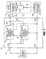
- FIG. 1 a block diagram representation of a preferred embodiment of the invention is indicated generally at 10, illustrating an apparatus for providing dual-segment, therapeutic pulses to iontophoretically deliver an ionic species, such as a drug in ionic form, or any other type of charged substance to be administered.
- an ionic species such as a drug in ionic form, or any other type of charged substance to be administered.
- Apparatus 10 comprises an electric power source 12, a pulse generator means 14 for generating a train of periodic pulses having a predetermined frequency, wherein each pulse has a predetermined pulse width as a function of the frequency (i.e., duty cycle) and a dual-segment pulse waveform according to the present invention as more fully described below, an active electrode 16 having an ionic drug to be delivered, and an indifferent electrode 18. Electrodes 16 and 18 are shown in electrical contact with a skin load S L at skin-electrode interface locations 16A and 18A, wherein skin load S L has been schematically illustrated by a simplified equivalent electrical model of skin tissue to receive iontophoretic therapy.
- Pulse generator means 14 further comprises input terminals 14a and 14b electrically coupled to power source 12 to energize pulse generator means 14, and output terminals 14c and 14d electrically coupled to electrodes 16 and 18 to deliver iontophoretic current to skin load S L .
- Electrodes 16 and 18 are of conventional design preferably adapted to provide uniform current density to skin load S L tissue in contact therewith.
- Apparatus 10 preferably comprises a small, lightweight, portable iontophoresis device suitable for use in direct adhesion application to the human skin to permit patient mobility. It should be understood, however, that it is the unique output of apparatus 10, namely, the dual-segment, therapeutic pulsed waveform, which constitutes a significant feature of the present invention.
- the features which are associated with the preferred embodiment of apparatus 10, namely, reduced size, reduced weight, portability, and reduced cost, comprise advantages of a secondary nature to that of the desired pulse waveform produced by the device.
- power source 12 can comprise a light-weight, button-type, dry element battery
- pulse generator means 14 can comprise circuitry which is primarily digital and can be readily fabricated as a custom integrated circuit at low cost and reduced size
- electrodes 16 and 18 can comprise conventional, slim, light-weight pads which adapt to skin surface contours and also provide support for power source 12 and pulse generator means 14.
- Pulse generator means 14 generates a train of periodic electrical pulses having a predetermined frequency ranging between 0.5 kHz and 50 kHz and a predetermined pulse width ranging between 10% and 80% of each cycle period, the waveform characteristics of each pulse thereof being controlled to provide a distinctive, dual-segment, therapeutic pulse waveform which is more fully described below.
- a pulse interval separates each pulse from a subsequent pulse in the pulse train, and the electrical attributes of each pulse interval are controlled to facilitate depolarization in the skin tissue and thereby reduce skin irritation in accordance with conventional practice.
- Pulse generator means 14 further comprises a first pulse segment generator means 20 for generating a first pulse segment of the dual-segment therapeutic pulse, and a second pulse segment generator means 22 for generating a second pulse segment of the dual-segment therapeutic pulse.
- the first pulse segment extends over a predetermined first portion of the pulse width, such first portion comprising not more than 50% of the pulse width.
- the second pulse segment extends over a subsequent second portion which comprises the remainder of the pulse width. It should be understood, however, that the second pulse segment may be generated such that it is co-extensive with all, some or none of the first pulse segment, provided that at least some part of the second pulse segment, which constitutes the subsequent second portion of the pulse width, follows the first pulse segment.
- each dual-segment, therapeutic pulse generated by pulse generator means 14 can comprise voltage-plus-current pulses, or current-plus-current pulses, as desired.
- the iontophoretic current delivered to skin load S L using the present invention is unidirectional throughout each therapeutic pulse, such iontophoretic current shown generally at arrow I L .
- first pulse generator means 20 provides a voltage output having a predetermined or controlled average amplitude ranging between 3 and 25 volts
- second pulse segment generator means 22 provides a current output having a predetermined or controlled average amplitude ranging between 0.01 and 5 milliamperes.
- a voltage output can be generated by a conventional voltage source having an output impedance which is low relative to that of the skin load impedance.
- a current output can be generated by a conventional current source having an output impedance which is high relative to that of the skin load impedance.
- Pulse generator means 14 preferably includes means for limiting the voltage amplitude and current amplitude of the pulsed output being delivered to skin load S L , which can comprise conventional voltage clamping and current limiting circuitry interconnected in a known manner.
- first pulse generator means 20 provides a current output having a predetermined or controlled first average amplitude ranging between 0.1 and 50 milliamperes
- second pulse segment generator means 22 provides a current output having a predetermined or controlled second average amplitude ranging between 0.01 and 5 milliamperes, wherein the first average current amplitude is greater than the second average current amplitude.
- the output of first pulse segment generator means 20 is coupled to output terminal 14c along a line 24.
- the output of second pulse segment generator means 22 is coupled to output terminal 14c along a line 26 to line 24 via summing node 28.
- pulse generator means 14 can include means for automatically adjusting to changing conditions in load conditions in order that a desired iontophoretic current flow is maintained.
- pulse generator means 14 can include a sensor-feedback means for sensing a parameter representative of iontophoretic current flow through the skin load S L , such as voltage, current, or impedance, including means for feedback of a signal representative of the parameter sensed and for controlling the electrical attributes of the dual-segment pulse waveform, such as pulse frequency, pulse width, and amplitude or relative duration of each pulse segment, as a function of the feedback so that the desired drug delivery rate is maintained.
- a sensor-feedback means for sensing a parameter representative of iontophoretic current flow through the skin load S L , such as voltage, current, or impedance, including means for feedback of a signal representative of the parameter sensed and for controlling the electrical attributes of the dual-segment pulse waveform, such as pulse frequency, pulse width, and amplitude or relative duration of each pulse segment, as a function of the feedback so that the desired drug delivery rate is maintained.
- first pulse segment generator means 20 and second pulse segment generator means 22 can comprise separate pulse generating circuit components for generating independent oscillating output, wherein pulse generator means 14 includes means for synchronizing their outputs to produce the desired dual-segment pulse waveform, such as by timing and gating circuitry.
- pulse generator means 14 can comprise a single pulse generator component, such as conventional oscillator means for providing an oscillating signal, wherein the oscillating signal enables output gates through which the respective outputs of first pulse segment generator means 20 and second pulse segment generator means 22 are coupled to the skin load in desired timed relation, thereby producing the desired dual-segment, therapeutic pulse.
- first pulse segment generator means 20 and second pulse segment generator means 22 can be interactively coupled as indicated generally by dashed line 30, to coordinate the relative timing of their respective output such that there may or may not be an overlap thereof.
- the second pulse segment may be generated by second pulse segment generator means 22 such that it is co-extensive with all, some or none of the first pulse segment.
- the output of pulse generator means 14 can comprise a dual-segment, voltage-plus-current, therapeutic pulse, wherein the second pulse segment which comprises a current output extending throughout the entire pulse width, such that the current output is superimposed upon the first pulse segment which comprises a voltage output.
- second pulse segment generator means 22 can be controlled to initiate its output immediately upon the termination of the output of first pulse segment generator means 20, such that the second pulse segment does not overlap with the first pulse segment but is merely subsequent thereto. Partial overlap between the second pulse segment and a trailing portion of the first pulse segment is also possible. It should be apparent that the duration of each pulse segment can be determined by various threshold detection circuitry, wherein the operation of first pulse segment generator means 20 and second pulse segment generator means 22 is controlled in response to parameters such as timing, voltage, current, impedance, and the like.
- Pulse generator means 14 can comprise a single voltage source of conventional design adapted to provide rectangular-wave, pulsed voltage output of predetermined amplitude, frequency and pulse width. Pulse generator means 14 further comprises switching circuitry of conventional design which couples the voltage output to output terminals 14c and 14d. The switching circuitry includes at least two circuit branches, each of which provide a pathway for current flow between the voltage source and output terminals 14c and 14d during each voltage pulse.
- a first circuit branch includes a selected first resistance and a second circuit branch includes a selected second resistance, wherein the resistances are selectively controlled such that the first resistance is less than the second resistance.
- the switching circuitry includes timing circuitry of conventional design which alternately couples the voltage output between the first circuit branch and the second circuit branch by switching between the branches according to a desired sequence and duration.
- the pulse generator means 14 thus provides a dual-segment, pulsed current output having an amplitude which varies between a predetermined first average current amplitude, which is a function of the amplitude of the voltage pulse and the first resistance, and a predetermined second average current amplitude, which is a function of the amplitude of the voltage pulse and the second resistance, such that the first current amplitude is greater than the second current amplitude.
- pulse generator means 14 can generate according to the present invention. While the particular waveform of each pulse segment is preferably rectangular or square-shaped, the waveform is not essentially limited to such type, and may comprise, for example, trapezoidal, ramped, or exponential waveforms.
- Comparative test results which were obtained using two different modalities of pulsed iontophoretic drug delivery, namely, a conventional pulsed DC current (“Pulsed DC”) and the dual-segment, voltage-plus-current, pulsed iontophoretic therapy of the present invention (“Dual-Segment”) are graphed in FIG.2.
- Data points corresponding to test results obtained using each modality have been graphed which indicate drug delivery efficiency as a function of pulse frequency.
- test conditions were as follows.
- the drug, hydromorphone hydrochloride was iontophoretically administered to four weanling pigs weighing approximately 10 kilograms under controlled, equivalent environmental conditions over a two-day study.
- Iontophoretic devices were used which provided a pulsed output according to the "Pulsed DC” and "Dual-Segment” modalities.
- the pulsed output for each modality was tested over six different pulse frequencies, namely, test frequencies of 1KHz, 2KHz, 3KHz, 4KHz, 5KHz and 6KHz.
- the duty cycle for each test frequency was 50%.
- a conventional, pulsed DC current output was delivered under the "Pulsed DC” modality, each current pulse thereof comprising a rectangular-type waveform having a substantially constant amplitude of 0.6 milliamperes.
- a dual-segment, voltage-plus-current, pulsed output was delivered under the "Dual-Segment” modality according to the present invention.
- Each "Dual-Segment” pulse consisted of a first pulse segment comprising a voltage output having a substantially constant amplitude of 24 volts, and a second pulse segment comprising a current output having a substantially constant amplitude of 0.6 milliamperes.
- the first pulse segment commenced at the beginning of each pulse, having a fixed duration of 1 microsecond regardless of the pulse width associated with the operating frequency used.
- the second pulse segment also commenced at the beginning of each pulse, having a variable duration such that the second pulse segment extended over the entire pulse width associated with the operating frequency used. Both pulse segments comprised a rectangular-type waveform.
- Iontophoretic devices driving skin electrodes located on the dorsal aspect of each pig were operated continously over a twelve-hour period using each modality.
- Each modality was tested on two pigs for each test frequency, each modality using a different pair of pigs.
- four separate data points are graphed for each test frequency in FIG. 2, which correspond to drug delivery measurements taken on each of the four pigs.
- the active electrode and indifferent electrode were disposed in an electrode housing available from Medtronic, Inc. as Electrode Housing Model No. 6462.
- the active electrode consisted of a gel formulation comprised of purified water (88%), polyvinyl alcohol "PVA” (8%), hydroxypropylmethylcellulose “HPMC” (2%), and hydromorphone hydrochloride (2%).
- the indifferent electrode consisted of a gel formulation available from Medtronic, Inc. as Gel Model No. 6467 INA.
- This gel formulation is comprised of HPMC (4%), PVA (6%), glycerol (10%), purified water (79.01%), sodium chloride (0.9%), potassium chloride (0.04%), and hydrated calcium chloride (CaCl2) (0.05%).
- the quantity of drug delivered was determined by measuring the residual drug remaining on the active electrode using conventional techniques including high pressure liquid chromatography.
- FIG. 3 a circuit diagram representation of a further preferred embodiment of the invention is indicated generally at 110, illustrating an apparatus for providing dual-segment, voltage-plus-current, therapeutic pulses.
- Apparatus 110 includes a sensor-feedback means for sensing an electrode potential during application of each pulse, such sensor-feedback means including means for feedback of a signal representative of the potential sensed and for controlling the pulse waveform as a function of the feedback signal.
- Apparatus 110 comprises an electric power source 112, a pulse generator means 114 for generating a train of periodic, dual-segment, voltage-plus-current, therapeutic pulses according to the present invention, an active electrode 116 having an ionic drug to be delivered, and an indifferent electrode 118.
- Power source 112 comprises a conventional, light-weight, button-type, dry element battery having a 6 volt potential. Electrodes 116 and 118 are of conventional design shown in electrical contact with skin tissue represented as a dashed-line block diagram as skin load S L .
- Pulse generator means 114 further comprises input terminals 114a and 114b for electrically coupling to power source 112 to energize pulse generator means 114, and output terminals 114c and 114d for electrically coupling to electrodes 116 and 118 to deliver iontophoretic current to skin load S L via electrode leads 116a and 118a respectively.
- Pulse generator means 114 further comprises oscillator circuit 120, sensor-feedback circuit 122, voltage gate circuit 124, current source circuit 126, and discharge circuit 128. Pulse generator means 114 provides a train of therapeutic pulses having a predetermined frequency of 2KHz. Each pulse has a controlled duration which defines a pulse width. Each pulse is separated from a subsequent pulse by an intervening pulse interval, the summation of each pulse width and subsequent pulse interval comprising a cycle period of approximately 500 microseconds.
- each pulse width and subsequent pulse interval are controlled to be approximately equal, such that a pulse width comprises approximately 50% of each cycle period.
- each cycle period generated by pulse generator means 114 is comprised of a pulse width extending over a first interval of time of approximately 250 microseconds, and a subsequent pulse interval extends over a second interval of time of approximately 250 microseconds, thereby defining a 50% duty cycle.
- Each therapeutic pulse generated by pulse generator means 114 is further comprised of two pulse segments having a controlled duration and amplitude.
- Each dual-segment, therapeutic pulse is comprised of a first pulse segment extending over a predetermined first portion of the pulse width and having a predetermined average voltage amplitude, and a second pulse segment extending over a subsequent second portion comprising the remainder of the pulse width and having a predetermined average current amplitude.
- Pulse generator means 114 includes means for generating a first pulse segment comprising a voltage output having a substantially constant 6 volt amplitude and a duration which can be varied as desired by the user, as more fully described below.
- Such first pulse segment generator means includes oscillator circuit 120, sensor-feedback circuit 122 and voltage gate circuit 124, which cooperate to generate the first pulse segment such that it commences at the onset of each therapeutic pulse and ends when a potential sensed at electrode 116 exceeds a predetermined threshold potential. This threshold potential may be controllably varied during operation as desired by the user, as more fully described below.
- Pulse generator means 114 includes means for generating a second pulse segment comprising a current output having a substantially constant amplitude which may be controllably varied during operation as desired by the user, as more fully described below.
- Such second pulse segment generator means includes oscillator circuit 120 and current source circuit 126, which cooperate to generate the second pulse segment commencing at the onset of each pulse and extending throughout the duration of the pulse width, such that it is co-extensive with the entirety of the first pulse segment.
- the dual-segment, therapeutic pulse thus generated by pulse generator means 114 is comprised of a first pulse segment corresponding to a substantially constant voltage output extending over an initial portion of the pulse width as controlled by the sensor-feedback circuitry, and a second pulse segment corresponding to a substantially constant current output which is superimposed upon the voltage output and extends over the entire pulse width.
- Oscillator circuit 120 is comprised of an oscillator 120a, an amplitude control circuit 120b, and a one-shot array circuit 120c.
- Oscillator 120a is a conventional pulse generating device adapted to generate square-wave, voltage pulses at a 2KHz frequency and an amplitude ranging between 0 and 6 volts.
- the oscillating output of oscillator 120a is coupled along a line 130 to amplitude control circuit 120b and one-shot array circuit 120c.
- Amplitude control circuit 120b comprised of variable resistor R1, adjustably varies the amplitude of the oscillating output of oscillator 120a to provide a desired pulsed voltage output along a line 136 to drive sensor-feedback circuit 122 and current source circuit 126, thereby establishing a desired threshold potential which determines the predetermined average voltage amplitude for the first pulse segment and establishing a desired average current amplitude for the second pulse segment.
- One-shot array circuit 120c comprises an array of 4 digital gates G1, G2, G3 and G4, which are arranged to provide leading edge detection corresponding to selected positive-going or negative-going changes in the output of oscillator 120a.
- an output is coupled from gate G1 along a line 132 to discharge circuit 128 thereby enabling depolarization to occur between electrodes 116 and 118 during each pulse interval in a known manner.
- an output is coupled from gate G4 along a line 134 to voltage gate circuit 124 thereby enabling a first pulse segment comprising a voltage output to be coupled across electrodes 116 and 118 only during a therapeutic pulse.
- Sensor-feedback circuit 122 is comprised of a threshold reference circuit 122a, a feedback-compare circuit 122b, and a feedback-control circuit 122c.
- Threshold reference circuit 122a is comprised of an operational amplifier A1, which is configured with resistors R2, R3 and R4 and capacitor C1 to operate as a buffer amplifier to provide a pulsed voltage output along a line 138 to feedback-compare circuit 122b, such output comprising the desired threshold potential which determines the predetermined average voltage amplitude for the pulsed voltage output of the first pulse segment.
- the potential of the output of threshold reference circuit 122a is a function of the adjusted amplitude of the output of amplitude control circuit 120b, which adjusted output is coupled along line 136 to the noninverting terminal of amplifier A1, and thus can be varied by the user as desired.
- Feedback-compare circuit 122b comprised of a comparator 140 which is configured with resistors R5 and R6, and capacitor C2, compares a first potential presented at the non-inverting terminal of comparator 140, which first potential comprises the threshold potential coupled along line 138, with a second potential presented at the inverting terminal of comparator 140, which second potential corresponds to a potential sensed at the active electrode 116 during each first pulse segment.
- Comparator 140 provides a comparator output along a line 142 to feedback-control circuit 122c as a function of such comparison.
- Feedback-compare circuit 122b includes a sensor-feedback means for sensing a potential at active electrode 116 during each first pulse segment and for feedback of the sensed potential to the inverting terminal of comparator 140.
- a potential at active electrode 116 is coupled along electrode lead 116a to output terminal 114c, and is further coupled along a line 144 to a feedback node 146.
- the sensor-feedback means of feedback-compare circuit 122b thus comprises a line 148 which couples a potential at feedback node 146, corresponding to a potential at active electrode 116, back to the inverting terminal of comparator 140.
- Feedback-control circuit 122c is comprised of an enhancement-type MOSFET T1.
- the drain terminal of MOSFET T1 is coupled to the supply voltage along a line 150 to the positive terminal of power source 112.
- the source terminal of MOSFET T1 is coupled along a line 152 to voltage gate circuit 124.
- Output from comparator 140 is coupled along line 142, which output provides bias to the gate of MOSFET T1.
- MOSFET T1 functions in conjunction with voltage gate circuit 124 to selectively gate the supply voltage across the output terminals 114c and 114d and through skin load S L , such that a first pulse segment, which is generated only during a first portion of each therapeutic pulse, has a controlled duration and voltage amplitude.
- voltage pulse from oscillator 120a which corresponds to the onset of a therapeutic pulse
- the potential sensed and fed back to comparator 140 will generally comprise a lower potential than the threshold potential being-compared against, thereby producing a comparator output having a high output state which will bias MOSFET T1 on.
- MOSFET T1 will thus continue to gate the supply voltage to voltage gate circuit 124 during the initial portion of each therapeutic pulse until the output from comparator 140 assumes a low output state causing MOSFET T1 to become biased off, which event will occur when the potential at the active electrode 116 exceeds the threshold potential.
- Voltage gate circuit 124 is comprised of digital gate 154, resistors R7 and R8, capacitor C3, and enhancement-type MOSFET T2.
- the drain terminal of MOSFET T2 is coupled to the voltage output of feedback-control circuit 122c by line 152.
- the source terminal of MOSFET T2 is coupled along a line 156 to an output node 158.
- Output node 158 electrically interconnects with line 144 to couple the voltage output of MOSFET T2 across output terminals 114c and 114d.
- Output from gate G4 of one-shot array circuit 120c is coupled along line 134 to the negative trigger input terminal 154a of gate 154.
- Output from gate 154 is coupled along a line 160, which output provides bias to the gate of MOSFET T2.
- the supply voltage will be fully coupled across the output terminals 114c and 114d, thereby producing a voltage output comprising the first pulse segment having a controlled duration and voltage amplitude.
- the predetermined average voltage amplitude of the first pulse segment is thus a function of the supply voltage.
- the predetermined first portion of each pulse width over which the first pulse segment extends is a function of the threshold potential selected. While the duration of the first pulse segment can be easily regulated by simple timing circuitry, it is considered preferable to do so using a sensor-feedback approach, such as sensor-feedback circuit 122 of the present embodiment.
- sensor-feedback circuit 122 automatically accommodates such variation by controlling the duration of such voltage pulse as a function of a feedback potential sensed across the load. Sensor-feedback circuit 122 thus automatically varies the duration of the first pulse segment as needed to meet the particular electrical characteristics of the patient's skin. Sensor-feedback circuit also prevents the skin being treated from being subjected to unsafe voltage levels which could produce burns or shocks.
- the amplitude of the applied voltage is limited by the battery potential, for example, and the potential generated across the skin load S L during each first pulse segment is limited by the selected threshold potential.
- Current source circuit 126 is comprised of operational amplifier A2, which is configured with resistors R9, R10, R11, R12, R13 and R14, and capacitor C4, to function as a constant current source which provides a pulsed current output along a line 162 to output node 158.
- Output node 158 electrically interconnects with line 144 to couple the pulsed current output of current source circuit 126 to output terminals 114c and 114d.
- a node 136a electrically interconnects with line 136 to couple the pulsed voltage output from amplitude control circuit 120b along a line 136b to the non-inverting terminal of amplifier A2.
- a pulsed voltage output from amplitude control circuit 120b having a desired amplitude is presented to current source circuit 126.
- Current source circuit 126 provides a pulsed current output having a constant current amplitude which is a function of the adjusted voltage amplitude of amplitude control circuit 120b and the voltage-to-current transfer function of current source circuit 126. It is preferred that the current amplitude remain substantially constant throughout the second pulse segment since the iontophoretic current delivered is directly proportional to the rate of ion migration. Oscillator circuit 120 and current source circuit 126 thus cooperate to generate a second pulse segment having a predetermined average current amplitude which can be controllably varied as desired, such that ionic drug is administered at a controlled rate.
- Pulse generator means 114 thus generates the second pulse segment throughout the duration of each therapeutic pulse, such that the pulsed current output comprising the second pulse segment is co-extensive with the entirety of the pulsed voltage output comprising the first pulse segment.
- Pulse generator means 114 can, however, generate the second pulse segment such that it is co-extensive with all, some or none of the first pulse segment, provided that at least some part of the second pulse segment, which constitutes the subsequent second portion of the pulse width, follows the first pulse segment.
- Pulse generator means 114 can include means for interactively controlling the generation of the first pulse segment and the second pulse segment, such that the second pulse segment is generated in the desired time relation with respect to the first pulse segment.
- current source circuit 126 can further comprise a gate disposed along line 136b which selectively couples pulsed voltage output from oscillator circuit 120 to current source circuit 126, wherein gate bias is controlled as a function of the output from comparator 140, such that output from current source circuit 126 commences immediately following completion of the voltage pulse comprising the first pulse segment.
- Discharge circuit 128, comprising bipolar transistor T3, which is configured with resistors R15 and R16, and capacitor C5, function as a means for discharging or depolarizing an unwanted potential which can develop during each therapeutic pulse across the electrodes 116 and 118 and skin load S L disposed therebetween.
- the collector terminal of transistor T3 is coupled along a line 164 to output node 158 which interconnects with active electrode 116 via line 144, output terminal 114c and electrode lead 116a.
- the emitter terminal of transistor T3 is coupled along a line 166 to a ground node 168 which electrically interconnects with indifferent electrode 118 via a line 170 coupling ground node 168 to output terminal 114d and electrode lead 118a.
- Output from gate G1 is coupled along line 132, which provides bias to the base terminal of transistor T3, such that transistor T3 functions as a switch which is in an "on” state to enable discharge therethrough during each pulse interval and in an "off” state during each pulse width.
Landscapes
- Health & Medical Sciences (AREA)
- Engineering & Computer Science (AREA)
- Biomedical Technology (AREA)
- Nuclear Medicine, Radiotherapy & Molecular Imaging (AREA)
- Radiology & Medical Imaging (AREA)
- Life Sciences & Earth Sciences (AREA)
- Animal Behavior & Ethology (AREA)
- General Health & Medical Sciences (AREA)
- Public Health (AREA)
- Veterinary Medicine (AREA)
- Electrotherapy Devices (AREA)
- Pharmaceuticals Containing Other Organic And Inorganic Compounds (AREA)
- Magnetic Treatment Devices (AREA)
- Glass Compositions (AREA)
- Production Of Multi-Layered Print Wiring Board (AREA)
- Inorganic Insulating Materials (AREA)
- Compositions Of Oxide Ceramics (AREA)
- Medicines Containing Material From Animals Or Micro-Organisms (AREA)
- Medicinal Preparation (AREA)
- Other Investigation Or Analysis Of Materials By Electrical Means (AREA)
Claims (10)
- Procédé de thérapie par médicament iontophorétique pulsée, dans lequel des impulsions électriques périodiques sont générées et appliquées pour exciter une électrode active (16, 116) et une électrode indifférente (18, 118) d'un dispositif iontophorétique en contact avec la peau d'un corps vivant pour lui administrer un médicament, comprenant:
la génération d'un train desdites impulsions périodiques à une fréquence prédéterminée, chacune de ses impulsions s'étendant sur un premier intervalle de temps qui définit une largeur d'impulsion prédéterminée de ladite impulsion, chacune de ses impulsions étant séparée d' une impulsion suivante par un second intervalle de temps qui définit un intervalle d'impulsion qui suit immédiatement ladite largeur d'impulsion, la somme de ladite largeur d'impulsion et de l'intervalle d'impulsion immédiatement suivant comprenant une période de cycle qui est l'inverse de ladite fréquence, caractérisé en ce que chaque impulsion a des caractéristiques de forme d'onde, comprenant:
un premier segment d'impulsion s'étendant sur une première partie prédéterminée de ladite largeur d'impulsion et ayant une première intensité de courant moyenne prédéterminée ou une amplitude de tension moyenne prédéterminée; et
un second segment d'impulsion s'étendant sur une seconde partie suivante comprenant le reste de ladite largeur d'impulsion et ayant une seconde intensité de courant moyenne prédéterminée supérieure à zéro;
dans lequel ladite première intensité de courant moyenne est supérieure à ladite seconde intensité de courant moyenne; et
dans lequel ladite première partie comporte pas plus de 50% de ladite largeur d'impulsion. - Procédé selon la revendication 1, dans lequel ladite largeur d'impulsion comporte entre 10% et 80% de ladite période de cycle.
- Procédé selon la revendication 2, dans lequel ladite fréquence desdites impulsions est comprise entre 0,5 et 50 kilohertz.
- Procédé selon la revendication 3, dans lequel ladite intensité de courant moyenne est comprise entre 0,1 et 50 milliampères, et ladite seconde intensité de courant moyenne est comprise entre 0,01 et 5 milliampères.
- Procédé selon la revendication 1, dans lequel ladite amplitude de tension moyenne est comprise entre 3 et 25 volts, et ladite seconde intensité de courant moyenne est comprise entre 0,01 et 5 milliampères.
- Appareil (10, 110) pour appliquer une thérapie à médicament iontophorétique pulsée à un corps vivant, ayant une source d'alimentation électrique (12, 112), une électrode active (16, 116) et une électrode indifférente (18, 118) aptes à être en contact avec la peau d'un corps vivant, et un moyen (14, 114) générateur d'impulsions couplé à ladite source d'alimentation, à ladite électrode active et à ladite électrode indifférente, ledit moyen générateur d'impulsions générant un train d'impulsions électriques périodiques et appliquant ledit train d'impulsions à la commande desdites électrodes pour faire circuler un courant continu total à travers la peau, comprenant:
un moyen (14, 114) générateur d'impulsions pour générer un train d'impulsions périodiques à une fréquence prédéterminée, chacune de ses impulsions s'étendant sur un premier intervalle de temps qui définit une largeur d'impulsion prédéterminée de ladite impulsion, chacune de ses impulsions étant séparée d'une impulsion suivante par un second intervalle de temps qui définit un intervalle d'impulsion qui suit immédiatement ladite largeur d'impulsion, la somme de ladite largeur d'impulsion et de l'intervalle d'impulsion immédiatement suivant comprenant une période de cycle qui est l'inverse de ladite fréquence, ledit moyen générateur d'impulsions étant caractérisé par:
un moyen (20, 120, 122, 124) générateur de premiers segments d'impulsions pour générer un premier segment d' impulsion s'étendant sur une première partie prédéterminée de ladite largeur d'impulsion et ayant une première intensité de courant moyenne prédéterminée ou une amplitude de tension moyenne prédéterminée; et
un moyen (22, 120, 126) générateur de seconds segments d'impulsions pour générer un second segment d'impulsion s'étendant sur une seconde partie suivante comprenant le reste de ladite largeur d'impulsion et ayant une seconde intensité de courant moyenne prédéterminée supérieure à zéro;
dans lequel ladite première intensité de courant moyenne est supérieure à ladite seconde intensité de courant moyenne; et
dans lequel ladite première partie comporte pas plus de 50% de ladite largeur d'impulsion. - Appareil selon la revendication 6, dans lequel ladite largeur d'impulsion comporte entre 10% et 80% de ladite période de cycle.
- Appareil selon la revendication 7, dans lequel ladite fréquence desdites impulsions est comprise entre 0,5 et 50 kilohertz.
- Appareil selon la revendication 8, dans lequel ladite première intensité de courant moyenne prédéterminée est comprise entre 0,1 et 50 milliampères, et ladite seconde intensité de courant moyenne est comprise entre 0,01 et 5 milliampères.
- Appareil selon la revendication 6, dasn lequel ladite amplitude de tension moyenne est comprise entre 3 et 25 volts, et ladite seconde intensité de courant moyenne est comprise entre 0,01 et 5 milliampères.
Applications Claiming Priority (3)
| Application Number | Priority Date | Filing Date | Title |
|---|---|---|---|
| US07/456,013 US5047007A (en) | 1989-12-22 | 1989-12-22 | Method and apparatus for pulsed iontophoretic drug delivery |
| US456013 | 1989-12-22 | ||
| PCT/US1990/007551 WO1991009645A1 (fr) | 1989-12-22 | 1990-12-19 | Procede et appareil d'administration iontophoretique par impulsion de medicaments |
Publications (2)
| Publication Number | Publication Date |
|---|---|
| EP0506879A1 EP0506879A1 (fr) | 1992-10-07 |
| EP0506879B1 true EP0506879B1 (fr) | 1994-09-14 |
Family
ID=23811093
Family Applications (1)
| Application Number | Title | Priority Date | Filing Date |
|---|---|---|---|
| EP91902909A Expired - Lifetime EP0506879B1 (fr) | 1989-12-22 | 1990-12-19 | Procede et appareil d'administration iontophoretique par impulsion de medicaments |
Country Status (14)
| Country | Link |
|---|---|
| US (1) | US5047007A (fr) |
| EP (1) | EP0506879B1 (fr) |
| JP (1) | JP3180129B2 (fr) |
| KR (1) | KR0154112B1 (fr) |
| AT (1) | ATE111367T1 (fr) |
| AU (1) | AU637674B2 (fr) |
| CA (1) | CA2069750C (fr) |
| DE (1) | DE69012587T2 (fr) |
| DK (1) | DK0506879T3 (fr) |
| ES (1) | ES2064084T3 (fr) |
| FI (1) | FI110309B (fr) |
| GR (1) | GR1001071B (fr) |
| NO (1) | NO306895B1 (fr) |
| WO (1) | WO1991009645A1 (fr) |
Families Citing this family (138)
| Publication number | Priority date | Publication date | Assignee | Title |
|---|---|---|---|---|
| US6956032B1 (en) | 1986-04-18 | 2005-10-18 | Carnegie Mellon University | Cyanine dyes as labeling reagents for detection of biological and other materials by luminescence methods |
| US5961482A (en) * | 1986-07-25 | 1999-10-05 | Rutgers, The State University Of New Jersey | Iontotherapeutic device and process and iontotherapeutic unit dose |
| US5749847A (en) * | 1988-01-21 | 1998-05-12 | Massachusetts Institute Of Technology | Delivery of nucleotides into organisms by electroporation |
| US5547467A (en) * | 1988-01-21 | 1996-08-20 | Massachusettes Institute Of Technology | Method for rapid temporal control of molecular transport across tissue |
| US5389069A (en) * | 1988-01-21 | 1995-02-14 | Massachusetts Institute Of Technology | Method and apparatus for in vivo electroporation of remote cells and tissue |
| ATE177959T1 (de) * | 1989-05-10 | 1999-04-15 | Drug Delivery Systems Inc | Elektrisches system mit mehreren signalen zur transdermalen medikamentenverabreichung |
| US4950229A (en) * | 1989-09-25 | 1990-08-21 | Becton, Dickinson And Company | Apparatus for an electrode used for iontophoresis |
| US5320597A (en) * | 1991-02-08 | 1994-06-14 | Becton, Dickinson And Company | Device and method for renewing electrodes during iontophoresis |
| JP2816886B2 (ja) * | 1990-03-05 | 1998-10-27 | 興和株式会社 | 生体通電装置 |
| US5302172A (en) * | 1990-03-15 | 1994-04-12 | North Carolina State University | Method and composition for iontophoresis |
| US6600950B1 (en) * | 1990-11-01 | 2003-07-29 | Robert Tapper | Iontophoretic treatment system |
| US6223076B1 (en) | 1990-11-01 | 2001-04-24 | Robert Tapper | Sweat control system |
| US6582416B2 (en) | 1990-11-01 | 2003-06-24 | Robert Tapper | Iontophoretic treatment system |
| US6139537A (en) * | 1990-11-01 | 2000-10-31 | Tapper; Robert | Iontophoretic treatment system |
| US5224927A (en) * | 1990-11-01 | 1993-07-06 | Robert Tapper | Iontophoretic treatment system |
| US6235013B1 (en) | 1990-11-01 | 2001-05-22 | Robert Tapper | Iontophoretic treatment system |
| US6238381B1 (en) | 1990-11-01 | 2001-05-29 | Robert Tapper | Iontophoretic treatment system |
| US6575957B1 (en) * | 1990-11-01 | 2003-06-10 | Robert Tapper | Iontophoretic treatment system |
| US5431625A (en) * | 1991-02-01 | 1995-07-11 | Empi, Inc. | Iontophoresis electronic device having a ramped output current |
| NL9100662A (nl) * | 1991-04-17 | 1992-11-16 | Optische Ind De Oude Delft Nv | Inrichting voor het uitvoeren van een iontoforese-behandeling bij een patient. |
| US5158081A (en) * | 1991-05-29 | 1992-10-27 | Trillion Medical Resources, Inc. | Method for treatment of soft tissue wounds by electrical stimulation |
| DE4137960A1 (de) * | 1991-11-19 | 1993-05-27 | Gerhard Prof Schauf | Therapiegeraet zur iontophorese im haut- und schweissdruesenbereich |
| US5246417A (en) * | 1991-12-11 | 1993-09-21 | Alza Corporation | Indicator for iontophoresis system |
| CA2084734C (fr) * | 1991-12-17 | 1998-12-01 | John L. Haynes | Systeme d'iontophorese dont les caracteristiques reduisent l'irritation cutanee |
| US5256137A (en) * | 1992-03-10 | 1993-10-26 | Becton Dickinson And Company | Biphasic power source for use in an iontophoretic drug delivery system |
| FR2687321B1 (fr) * | 1992-02-14 | 1999-04-16 | Elf Aquitaine | Dispositif d'ionophorese pour l'administration transcutanee d'une quantite totale donnee d'un principe actif a un sujet. |
| DE4217039C2 (de) * | 1992-05-22 | 1995-07-13 | Boehringer Ingelheim Kg | Vorrichtung für die iontophoretische Applikation, bei der der Wirkstofffluß maximiert ist, Vorrichtung zur Bestimmung der zugehörigen Frequenz sowie entsprechendes Iontophoreseverfahren |
| US5282482A (en) * | 1992-06-18 | 1994-02-01 | Wilk Peter J | Pressure relief support pad |
| US5380271A (en) * | 1992-09-24 | 1995-01-10 | Alza Corporation | Electrotransport agent delivery device and method |
| US5306235A (en) * | 1992-09-30 | 1994-04-26 | Becton Dickinson And Company | Failsafe iontophoresis drug delivery system |
| US5634899A (en) * | 1993-08-20 | 1997-06-03 | Cortrak Medical, Inc. | Simultaneous cardiac pacing and local drug delivery method |
| US5415629A (en) * | 1993-09-15 | 1995-05-16 | Henley; Julian L. | Programmable apparatus for the transdermal delivery of drugs and method |
| CA2172991A1 (fr) * | 1993-09-30 | 1995-04-06 | Burton H. Sage, Jr. | Dispositif d'administration de medicaments par iontophorese et son procede |
| US5387189A (en) * | 1993-12-02 | 1995-02-07 | Alza Corporation | Electrotransport delivery device and method of making same |
| DK0752898T3 (da) * | 1994-03-30 | 1999-02-15 | Alza Corp | Mindskning af hudirritation ved elektrotransport-tilførsel |
| US5540654A (en) * | 1994-09-02 | 1996-07-30 | North Carolina State University | Iontophoretic electrode |
| US7027859B1 (en) * | 1994-09-26 | 2006-04-11 | Alza Corporation | Electrotransport delivery device having improved safety and reduced abuse potential |
| US5551953A (en) * | 1994-10-31 | 1996-09-03 | Alza Corporation | Electrotransport system with remote telemetry link |
| US5562607A (en) * | 1995-01-18 | 1996-10-08 | Alza Corporation | Electrotransport device having reusable controller power saver |
| US5843014A (en) * | 1995-03-24 | 1998-12-01 | Alza Corporation | Display for an electrotransport delivery device |
| US5879322A (en) * | 1995-03-24 | 1999-03-09 | Alza Corporation | Self-contained transdermal drug delivery device |
| IE960312A1 (en) * | 1995-06-02 | 1996-12-11 | Alza Corp | An electrotransport delivery device with voltage boosting¹circuit |
| US5978701A (en) * | 1995-06-02 | 1999-11-02 | Alza Corporation | Electrotransport device with separable controller and drug unit and method of setting controller output |
| IE960375A1 (en) * | 1995-06-05 | 1996-12-11 | Alza Corp | Device for transdermal electrotransport delivery of fentanyl¹and sufentanil |
| DE122006000022I1 (de) | 1995-06-05 | 2006-09-21 | Alza Corp | Vorrichtung zur Transdermalen iontophoretischen verabreichung von Fentanyl und Sufentanil |
| US6216033B1 (en) | 1996-05-22 | 2001-04-10 | Alza Corporation | Device for transdermal electrotransport delivery of fentanyl and sufentanil |
| US6881208B1 (en) | 1995-06-05 | 2005-04-19 | Joseph B. Phipps | Method and device for transdermal electrotransport delivery of fentanyl and sufentanil |
| US6425892B2 (en) | 1995-06-05 | 2002-07-30 | Alza Corporation | Device for transdermal electrotransport delivery of fentanyl and sufentanil |
| US6355025B1 (en) | 1995-06-07 | 2002-03-12 | Alza Corporation | Adjustable electrotransport drug delivery using a fixed output controller |
| US5983130A (en) * | 1995-06-07 | 1999-11-09 | Alza Corporation | Electrotransport agent delivery method and apparatus |
| US7572252B1 (en) | 1995-06-07 | 2009-08-11 | Alza Corporation | Electrotransport agent delivery method and apparatus |
| US5983131A (en) * | 1995-08-11 | 1999-11-09 | Massachusetts Institute Of Technology | Apparatus and method for electroporation of tissue |
| US6167301A (en) * | 1995-08-29 | 2000-12-26 | Flower; Ronald J. | Iontophoretic drug delivery device having high-efficiency DC-to-DC energy conversion circuit |
| US6086572A (en) * | 1996-05-31 | 2000-07-11 | Alza Corporation | Electrotransport device and method of setting output |
| US6718201B1 (en) * | 1996-06-07 | 2004-04-06 | Alza Corporation | Electrotransport agent delivery method and apparatus |
| US5911223A (en) * | 1996-08-09 | 1999-06-15 | Massachusetts Institute Of Technology | Introduction of modifying agents into skin by electroporation |
| US5869326A (en) * | 1996-09-09 | 1999-02-09 | Genetronics, Inc. | Electroporation employing user-configured pulsing scheme |
| PT941085E (pt) * | 1996-11-14 | 2003-08-29 | Alza Corp | Dispositivo para administracao electricamente assistida de agentes como a lidocaina e a epinefrina |
| US5935156A (en) * | 1997-03-12 | 1999-08-10 | Microleve International, Ltd. | Method and apparatus for administering microcurrent electrotherapy treatment |
| US6085115A (en) * | 1997-05-22 | 2000-07-04 | Massachusetts Institite Of Technology | Biopotential measurement including electroporation of tissue surface |
| US6047208A (en) * | 1997-08-27 | 2000-04-04 | Becton, Dickinson And Company | Iontophoretic controller |
| US6295469B1 (en) | 1997-11-14 | 2001-09-25 | Alza Corporation | Formulation for electrically assisted delivery of lidocaine and epinephrine |
| CA2319638C (fr) * | 1998-01-28 | 2008-02-12 | Alza Corporation | Montage d'une electrode avec un dispositif d'electro-apport ayant une resistance initiale faible |
| US5945123A (en) * | 1998-04-02 | 1999-08-31 | K-V Pharmaceutical Company | Maximizing effectiveness of substances used to improve health and well being |
| US20040062802A1 (en) * | 1998-04-02 | 2004-04-01 | Hermelin Victor M. | Maximizing effectiveness of substances used to improve health and well being |
| DE19845065A1 (de) * | 1998-05-15 | 1999-11-25 | Siemens Ag | Vorrichtung zur kontaktlosen Übertragung von Daten |
| US6148231A (en) | 1998-09-15 | 2000-11-14 | Biophoretic Therapeutic Systems, Llc | Iontophoretic drug delivery electrodes and method |
| US6858018B1 (en) | 1998-09-28 | 2005-02-22 | Vyteris, Inc. | Iontophoretic devices |
| AU766913B2 (en) | 1998-11-02 | 2003-10-23 | Alza Corporation | Electrotransport device including a compatible antimicrobial agent |
| BR0008123A (pt) | 1999-02-10 | 2001-11-13 | Gmp Drug Delivery Inc | Dispositivo baseado em emplastro para aumentar aliberação local de um agente de tratamento paradentro de tecidos alvo, e, processo de liberaçãode um agente de tratamento para dentro detecidos alvo de uma vesìcula corporal |
| US7127285B2 (en) | 1999-03-12 | 2006-10-24 | Transport Pharmaceuticals Inc. | Systems and methods for electrokinetic delivery of a substance |
| US6792306B2 (en) | 2000-03-10 | 2004-09-14 | Biophoretic Therapeutic Systems, Llc | Finger-mounted electrokinetic delivery system for self-administration of medicaments and methods therefor |
| US6477410B1 (en) | 2000-05-31 | 2002-11-05 | Biophoretic Therapeutic Systems, Llc | Electrokinetic delivery of medicaments |
| US6385488B1 (en) | 1999-05-20 | 2002-05-07 | Vyteris, Inc. | Circuits for increasing the reliability of an iontophoretic system |
| US6512950B2 (en) | 2000-02-18 | 2003-01-28 | University Of Utah Research Foundation | Methods for delivering agents using alternating current |
| CA2400074A1 (fr) | 2000-02-18 | 2001-08-23 | William I. Higuchi | Procedes d'extraction de substances par utilisation de courant alternatif |
| JP4922537B2 (ja) * | 2000-09-11 | 2012-04-25 | アルザ・コーポレーシヨン | 経皮性の電気輸送装置とその製造方法 |
| US7137975B2 (en) | 2001-02-13 | 2006-11-21 | Aciont, Inc. | Method for increasing the battery life of an alternating current iontophoresis device using a barrier-modifying agent |
| CA2443326A1 (fr) * | 2001-04-04 | 2002-10-17 | Alza Corporation | Dispositif d'administration transdermique par electrotransport comprenant une composition de reservoir compatible antimicrobienne |
| US6770080B2 (en) | 2001-04-26 | 2004-08-03 | Fenestra Medical, Inc. | Mechanically registered videoscopic myringotomy/tympanostomy tube placement system |
| ITTO20010534A1 (it) * | 2001-06-04 | 2002-12-04 | Igea Srl | Dispositivo e metodo per elettroporazione che riduce la contrazione muscolare e la sensazione di dolore. |
| US6810877B2 (en) * | 2001-08-02 | 2004-11-02 | Medical Electronics Devices Corp. | High sensitivity pressure switch |
| DE60231148D1 (de) * | 2001-12-19 | 2009-03-26 | Alza Corp | Reservoir-gehäuse mit einer integrierten leitenden region |
| WO2003053512A2 (fr) * | 2001-12-20 | 2003-07-03 | Alza Corporation | Dispositif d'electrotransport presentant un boitier de reservoir integralement moule |
| US6823202B2 (en) * | 2002-04-01 | 2004-11-23 | Iomed, Inc. | Iontophoretic power supply |
| US20060009730A2 (en) * | 2002-07-29 | 2006-01-12 | Eemso, Inc. | Iontophoretic Transdermal Delivery of One or More Therapeutic Agents |
| US7458982B2 (en) * | 2002-10-04 | 2008-12-02 | Photokinetix, Inc. | Photokinetic delivery of biologically active substances using pulsed incoherent light |
| TW200416015A (en) * | 2003-02-17 | 2004-09-01 | Wei-Gung Wang | Device for selectively generating hydrogen ions in an aqueous solution |
| US8224435B2 (en) * | 2003-03-31 | 2012-07-17 | Alza Corporation | Electrotransport device having a reservoir housing having a flexible conductive element |
| AU2004291040A1 (en) * | 2003-11-13 | 2005-06-02 | Alza Corporation | System and method for transdermal delivery |
| US20050220439A1 (en) * | 2004-03-19 | 2005-10-06 | Carton Owen A | Interactive multimedia system and method |
| US20050226921A1 (en) * | 2004-04-13 | 2005-10-13 | Kortzebom Robert N | Non-invasive analysis and controlled dosage transdermal active patch |
| UY28935A1 (es) * | 2004-06-03 | 2005-07-29 | Alza Corp | Sistema y metodo para la administracion transdermica de un anticoagulante |
| WO2006133102A2 (fr) * | 2005-06-03 | 2006-12-14 | Trans-Dermal Patents Company, Llc | Systeme d'administration d'agent et ses utilisations |
| US20090143761A1 (en) * | 2005-06-03 | 2009-06-04 | Transdermal Patents Company, Llc | Agent delivery system and uses of same |
| JP2007037868A (ja) * | 2005-08-05 | 2007-02-15 | Transcutaneous Technologies Inc | 経皮投与装置及びその制御方法 |
| WO2007026671A1 (fr) * | 2005-08-29 | 2007-03-08 | Transcu Ltd. | Dispositif de iontophorèse permettant de selectionner un medicament a administrer selon les informations provenant d'un capteur |
| US20070071807A1 (en) * | 2005-09-28 | 2007-03-29 | Hidero Akiyama | Capsule-type drug-releasing device and capsule-type drug-releasing device system |
| US20070149916A1 (en) * | 2005-12-22 | 2007-06-28 | Alza Corporation | Dry matrices as drug reservoirs in electrotransport applications |
| US20080009782A1 (en) * | 2006-06-28 | 2008-01-10 | Alza Corporation | Methods and Devices for Transdermal Electrotransport Delivery of Lofentanil and Carfentanil |
| KR100730582B1 (ko) * | 2006-11-20 | 2007-06-20 | 아람휴비스(주) | 이온토포레시스 장치 |
| KR20090106492A (ko) * | 2006-12-01 | 2009-10-09 | 티티아이 엘뷰 가부시키가이샤 | 경피성 전달 장치와 같은 장치에 전력을 제공하거나 제어하기 위한 시스템, 장치, 및 방법 |
| WO2009081262A1 (fr) | 2007-12-18 | 2009-07-02 | Insuline Medical Ltd. | Dispositif d'administration de médicament doté d'un capteur pour un fonctionnement en boucle fermée |
| US8622991B2 (en) | 2007-03-19 | 2014-01-07 | Insuline Medical Ltd. | Method and device for drug delivery |
| CN104069567A (zh) | 2007-03-19 | 2014-10-01 | 茵苏莱恩医药有限公司 | 药物输送设备 |
| US9220837B2 (en) | 2007-03-19 | 2015-12-29 | Insuline Medical Ltd. | Method and device for drug delivery |
| US8052693B2 (en) | 2007-04-19 | 2011-11-08 | Acclarent, Inc. | System and method for the simultaneous automated bilateral delivery of pressure equalization tubes |
| US8197844B2 (en) | 2007-06-08 | 2012-06-12 | Activatek, Inc. | Active electrode for transdermal medicament administration |
| EP2043733A1 (fr) | 2007-06-26 | 2009-04-08 | Alza Corporation | Procédés et dispositifs d'administration de lofentanil et de carfentanil par électrotransport transdermique |
| US8192420B2 (en) | 2007-12-20 | 2012-06-05 | Acclarent, Inc. | Iontophoresis methods |
| US8862223B2 (en) | 2008-01-18 | 2014-10-14 | Activatek, Inc. | Active transdermal medicament patch and circuit board for same |
| US8840602B2 (en) | 2008-07-31 | 2014-09-23 | Acclarent, Inc. | Systems and methods for anesthetizing ear tissue |
| US8452392B2 (en) | 2008-07-31 | 2013-05-28 | Acclarent, Inc. | Systems and methods for anesthetizing ear tissue |
| US8150525B2 (en) * | 2008-08-27 | 2012-04-03 | Johnson & Johnson Consumer Companies, Inc. | Treatment of hyperhydrosis |
| AU2009312474B2 (en) | 2008-11-07 | 2014-12-04 | Insuline Medical Ltd. | Device and method for drug delivery |
| WO2010078313A1 (fr) * | 2008-12-30 | 2010-07-08 | Nupathe, Inc. | Régulation électronique d'un système de distribution de médicament |
| US9539146B2 (en) | 2009-07-15 | 2017-01-10 | Tusker Medical, Inc. | Trigger assembly for tympanostomy tube delivery device |
| US9770366B2 (en) | 2009-07-15 | 2017-09-26 | Tusker Medical, Inc. | Tympanic membrane pressure equalization tube delivery system |
| AU2011332187B2 (en) | 2010-11-23 | 2016-03-03 | Teva Pharmaceuticals International Gmbh | User-activated self-contained co-packaged iontophoretic drug delivery system |
| US8428708B1 (en) | 2012-05-21 | 2013-04-23 | Incline Therapeutics, Inc. | Self-test for analgesic product |
| US8428709B1 (en) | 2012-06-11 | 2013-04-23 | Incline Therapeutics, Inc. | Current control for electrotransport drug delivery |
| US8781571B2 (en) | 2011-03-31 | 2014-07-15 | Incline Therapeutics, Inc. | Switch validation circuit and method |
| US9731121B2 (en) | 2011-03-31 | 2017-08-15 | Incline Therapeutics, Inc. | Switch validation circuit and method |
| JP5759615B2 (ja) * | 2011-04-08 | 2015-08-05 | コヴィディエン リミテッド パートナーシップ | 腎交感神経の除神経およびイオン導入薬物送達のためのイオン導入カテーテルシステムならびに方法 |
| MX2014001073A (es) | 2011-07-25 | 2014-03-21 | Acclarent Inc | Sistema y metodo personalizable para anestesiar la membrana timpanica. |
| US9364648B2 (en) | 2012-05-30 | 2016-06-14 | Tusker Medical, Inc. | Adhesive earplugs useful for sealing the ear canal |
| US9681891B2 (en) | 2013-03-14 | 2017-06-20 | Tusker Medical, Inc. | Tympanostomy tube delivery device with cutting dilator |
| US9320652B2 (en) | 2013-03-14 | 2016-04-26 | Tusker Medical, Inc. | Features to improve and sense tympanic membrane apposition by tympanostomy tube delivery instrument |
| US10130808B2 (en) | 2013-03-14 | 2018-11-20 | Tusker Medical, Inc. | System and method for providing iontophoresis at tympanic membrane |
| US20160038341A1 (en) | 2014-08-08 | 2016-02-11 | Acclarent, Inc. | Tympanostomy tube delivery device with elastomeric brake |
| US10195086B2 (en) | 2014-08-11 | 2019-02-05 | Tusker Medical, Inc. | Tympanostomy tube delivery device with rotatable |
| US9833359B2 (en) | 2014-08-12 | 2017-12-05 | Tusker Medical, Inc. | Tympanostomy tube delivery device with cutter force clutch |
| US9833360B2 (en) | 2014-08-12 | 2017-12-05 | Tusker Medical, Inc. | Tympanostomy tube delivery device with replaceable shaft portion |
| CA2936740C (fr) | 2014-10-31 | 2017-10-10 | Purdue Pharma | Methodes et compositions destinees au traitement du trouble de deficit d'attention |
| US10016304B2 (en) | 2015-07-16 | 2018-07-10 | Tusker Medical, Inc. | Earplug assembly for iontophoresis system |
| US10722473B2 (en) | 2018-11-19 | 2020-07-28 | Purdue Pharma L.P. | Methods and compositions particularly for treatment of attention deficit disorder |
| JP7542202B2 (ja) * | 2019-02-27 | 2024-08-30 | パナソニックIpマネジメント株式会社 | 美容装置 |
| CN114367036A (zh) * | 2022-01-27 | 2022-04-19 | 浙江宜格企业管理集团有限公司 | 多功能复合电场离子导入系统及导入仪 |
Family Cites Families (17)
| Publication number | Priority date | Publication date | Assignee | Title |
|---|---|---|---|---|
| US3794910A (en) * | 1971-07-26 | 1974-02-26 | Sherwood Medical Ind Inc | Iontophoresis and conductivity analysis circuit |
| US3991755A (en) * | 1973-07-27 | 1976-11-16 | Medicon, Inc. | Iontophoresis apparatus for applying local anesthetics |
| US4019510A (en) * | 1975-02-10 | 1977-04-26 | Sybron Corporation | Therapeutic method of using low intensity direct current generator with polarity reversal |
| US4141359A (en) * | 1976-08-16 | 1979-02-27 | University Of Utah | Epidermal iontophoresis device |
| JPS5347192A (en) * | 1976-10-13 | 1978-04-27 | Matsushita Electric Industrial Co Ltd | Device for introducing fluorine ion to tooth |
| US4301794A (en) * | 1978-10-18 | 1981-11-24 | Robert Tapper | Method for iontophoretic treatment |
| US4340047A (en) * | 1978-10-18 | 1982-07-20 | Robert Tapper | Iontophoretic treatment apparatus |
| US4292968A (en) * | 1979-11-26 | 1981-10-06 | Sybron Corporation | Electric supply for ion therapy |
| US4406658A (en) * | 1981-03-06 | 1983-09-27 | Medtronic, Inc. | Iontophoretic device with reversible polarity |
| US4456012A (en) * | 1982-02-22 | 1984-06-26 | Medtronic, Inc. | Iontophoretic and electrical tissue stimulation device |
| US4808152A (en) * | 1983-08-18 | 1989-02-28 | Drug Delivery Systems Inc. | System and method for controlling rate of electrokinetic delivery of a drug |
| CA1262564A (fr) * | 1983-09-01 | 1989-10-31 | Minoru Sasaki | Dispositif d'iontophorese |
| US4846950A (en) * | 1983-09-08 | 1989-07-11 | Montefiore Hospital Assn Of Western Pa | Cyclic controlled electrolysis apparatus |
| US4543956A (en) * | 1984-05-24 | 1985-10-01 | Cordis Corporation | Biphasic cardiac pacer |
| US4725263A (en) * | 1986-07-31 | 1988-02-16 | Medtronic, Inc. | Programmable constant current source transdermal drug delivery system |
| AU615188B2 (en) * | 1987-05-28 | 1991-09-26 | Drug Delivery Systems Inc. | Pulsating transdermal drug delivery system |
| JPS6456060A (en) * | 1987-08-27 | 1989-03-02 | Hayashibara Takeshi | Low frequency medical treatment device |
-
1989
- 1989-12-22 US US07/456,013 patent/US5047007A/en not_active Expired - Lifetime
-
1990
- 1990-12-19 EP EP91902909A patent/EP0506879B1/fr not_active Expired - Lifetime
- 1990-12-19 DK DK91902909.0T patent/DK0506879T3/da active
- 1990-12-19 KR KR1019920701462A patent/KR0154112B1/ko not_active Expired - Lifetime
- 1990-12-19 JP JP50328991A patent/JP3180129B2/ja not_active Expired - Lifetime
- 1990-12-19 CA CA002069750A patent/CA2069750C/fr not_active Expired - Lifetime
- 1990-12-19 ES ES91902909T patent/ES2064084T3/es not_active Expired - Lifetime
- 1990-12-19 AT AT91902909T patent/ATE111367T1/de not_active IP Right Cessation
- 1990-12-19 AU AU71480/91A patent/AU637674B2/en not_active Ceased
- 1990-12-19 DE DE69012587T patent/DE69012587T2/de not_active Expired - Lifetime
- 1990-12-19 WO PCT/US1990/007551 patent/WO1991009645A1/fr not_active Ceased
- 1990-12-21 GR GR900100877A patent/GR1001071B/el unknown
-
1992
- 1992-06-17 FI FI922830A patent/FI110309B/fi active
- 1992-06-19 NO NO922441A patent/NO306895B1/no unknown
Also Published As
| Publication number | Publication date |
|---|---|
| NO922441L (no) | 1992-08-19 |
| FI922830A0 (fi) | 1992-06-17 |
| ATE111367T1 (de) | 1994-09-15 |
| NO922441D0 (no) | 1992-06-19 |
| KR0154112B1 (ko) | 1998-11-16 |
| DE69012587D1 (de) | 1994-10-20 |
| CA2069750A1 (fr) | 1991-06-23 |
| JP3180129B2 (ja) | 2001-06-25 |
| EP0506879A1 (fr) | 1992-10-07 |
| WO1991009645A1 (fr) | 1991-07-11 |
| FI110309B (fi) | 2002-12-31 |
| CA2069750C (fr) | 2001-04-10 |
| NO306895B1 (no) | 2000-01-10 |
| FI922830A7 (fi) | 1992-06-17 |
| GR1001071B (el) | 1993-04-28 |
| US5047007A (en) | 1991-09-10 |
| JPH05504703A (ja) | 1993-07-22 |
| GR900100877A (en) | 1992-05-12 |
| DK0506879T3 (da) | 1995-02-13 |
| ES2064084T3 (es) | 1995-01-16 |
| AU637674B2 (en) | 1993-06-03 |
| DE69012587T2 (de) | 1995-01-12 |
| KR920703147A (ko) | 1992-12-17 |
| AU7148091A (en) | 1991-07-24 |
Similar Documents
| Publication | Publication Date | Title |
|---|---|---|
| EP0506879B1 (fr) | Procede et appareil d'administration iontophoretique par impulsion de medicaments | |
| AU688644B2 (en) | Electrotransport delivery device | |
| CN1607970B (zh) | 皮肤贴片 | |
| EP0879070B1 (fr) | Therapie par ionophorese | |
| KR100433089B1 (ko) | 2상 파형으로 근육 조직을 자극하기 위한 장치 | |
| JP3300953B2 (ja) | 体動制御型電子伝達薬剤供給装置 | |
| US4764164A (en) | Iontophoresis device | |
| JP3343348B2 (ja) | イオン電気導入薬剤投与中の刺激を軽減させるためのデバイス | |
| US6484056B2 (en) | System and method of generating a high efficiency biphasic defibrillation waveform for use in an implantable cardioverter/defibrillator (ICD) | |
| WO2007106270A2 (fr) | Courants galvaniques ou alternatifs lents stimulants à effets physiologiques thérapeutiques | |
| DE69112533D1 (de) | Einpflanzbares iontophoretisches Abgabesystem. | |
| WO1997027899A9 (fr) | Therapie par ionophorese | |
| WO1997007853A1 (fr) | Dispositif d'iontophorese et procede approprie de regulation du courant | |
| CA2172991A1 (fr) | Dispositif d'administration de medicaments par iontophorese et son procede | |
| JPH0245461B2 (fr) | ||
| EP0308572A2 (fr) | Dispositif d'iontophorèse | |
| JPH0638515A (ja) | 電圧発生装置、医薬品経皮投与装置及び電気刺激装置 | |
| JPH0741469Y2 (ja) | 低周波治療器 | |
| JP2001190695A (ja) | 2相電気式心臓整調装置 | |
| JPH0767971A (ja) | イオントフォレーシス用デバイス | |
| MXPA97004049A (en) | Electrotranspal supply device |
Legal Events
| Date | Code | Title | Description |
|---|---|---|---|
| PUAI | Public reference made under article 153(3) epc to a published international application that has entered the european phase |
Free format text: ORIGINAL CODE: 0009012 |
|
| AK | Designated contracting states |
Kind code of ref document: A1 Designated state(s): AT BE CH DE DK ES FR GB GR IT LI LU NL SE |
|
| 17P | Request for examination filed |
Effective date: 19920603 |
|
| RAP1 | Party data changed (applicant data changed or rights of an application transferred) |
Owner name: ALZA CORPORATION |
|
| 17Q | First examination report despatched |
Effective date: 19930329 |
|
| GRAA | (expected) grant |
Free format text: ORIGINAL CODE: 0009210 |
|
| AK | Designated contracting states |
Kind code of ref document: B1 Designated state(s): AT BE CH DE DK ES FR GB GR IT LI LU NL SE |
|
| REF | Corresponds to: |
Ref document number: 111367 Country of ref document: AT Date of ref document: 19940915 Kind code of ref document: T |
|
| REF | Corresponds to: |
Ref document number: 69012587 Country of ref document: DE Date of ref document: 19941020 |
|
| ITF | It: translation for a ep patent filed | ||
| ET | Fr: translation filed | ||
| REG | Reference to a national code |
Ref country code: ES Ref legal event code: FG2A Ref document number: 2064084 Country of ref document: ES Kind code of ref document: T3 |
|
| EAL | Se: european patent in force in sweden |
Ref document number: 91902909.0 |
|
| REG | Reference to a national code |
Ref country code: DK Ref legal event code: T3 |
|
| REG | Reference to a national code |
Ref country code: GR Ref legal event code: FG4A Free format text: 3014353 |
|
| PLBE | No opposition filed within time limit |
Free format text: ORIGINAL CODE: 0009261 |
|
| STAA | Information on the status of an ep patent application or granted ep patent |
Free format text: STATUS: NO OPPOSITION FILED WITHIN TIME LIMIT |
|
| 26N | No opposition filed | ||
| PGFP | Annual fee paid to national office [announced via postgrant information from national office to epo] |
Ref country code: AT Payment date: 19971124 Year of fee payment: 8 |
|
| PGFP | Annual fee paid to national office [announced via postgrant information from national office to epo] |
Ref country code: GR Payment date: 19971128 Year of fee payment: 8 |
|
| PGFP | Annual fee paid to national office [announced via postgrant information from national office to epo] |
Ref country code: SE Payment date: 19981203 Year of fee payment: 9 |
|
| PG25 | Lapsed in a contracting state [announced via postgrant information from national office to epo] |
Ref country code: AT Free format text: LAPSE BECAUSE OF NON-PAYMENT OF DUE FEES Effective date: 19981219 |
|
| PG25 | Lapsed in a contracting state [announced via postgrant information from national office to epo] |
Ref country code: GR Free format text: LAPSE BECAUSE OF NON-PAYMENT OF DUE FEES Effective date: 19981231 |
|
| PG25 | Lapsed in a contracting state [announced via postgrant information from national office to epo] |
Ref country code: SE Free format text: LAPSE BECAUSE OF NON-PAYMENT OF DUE FEES Effective date: 19991220 |
|
| EUG | Se: european patent has lapsed |
Ref document number: 91902909.0 |
|
| REG | Reference to a national code |
Ref country code: GB Ref legal event code: IF02 |
|
| REG | Reference to a national code |
Ref country code: CH Ref legal event code: PFA Owner name: ALZA CORPORATION Free format text: ALZA CORPORATION#950 PAGE MILL ROAD#PALO ALTO/CA (US) -TRANSFER TO- ALZA CORPORATION#950 PAGE MILL ROAD#PALO ALTO/CA (US) |
|
| PGFP | Annual fee paid to national office [announced via postgrant information from national office to epo] |
Ref country code: DK Payment date: 20091211 Year of fee payment: 20 Ref country code: LU Payment date: 20091221 Year of fee payment: 20 Ref country code: CH Payment date: 20091215 Year of fee payment: 20 |
|
| PGFP | Annual fee paid to national office [announced via postgrant information from national office to epo] |
Ref country code: NL Payment date: 20091204 Year of fee payment: 20 |
|
| PGFP | Annual fee paid to national office [announced via postgrant information from national office to epo] |
Ref country code: IT Payment date: 20091218 Year of fee payment: 20 Ref country code: GB Payment date: 20091216 Year of fee payment: 20 Ref country code: ES Payment date: 20100113 Year of fee payment: 20 Ref country code: FR Payment date: 20091221 Year of fee payment: 20 |
|
| PGFP | Annual fee paid to national office [announced via postgrant information from national office to epo] |
Ref country code: DE Payment date: 20091217 Year of fee payment: 20 Ref country code: BE Payment date: 20091224 Year of fee payment: 20 |
|
| REG | Reference to a national code |
Ref country code: NL Ref legal event code: V4 Effective date: 20101219 |
|
| BE20 | Be: patent expired |
Owner name: *ALZA CORP. Effective date: 20101219 |
|
| REG | Reference to a national code |
Ref country code: CH Ref legal event code: PL |
|
| REG | Reference to a national code |
Ref country code: GB Ref legal event code: PE20 Expiry date: 20101218 |
|
| REG | Reference to a national code |
Ref country code: DK Ref legal event code: EUP |
|
| PG25 | Lapsed in a contracting state [announced via postgrant information from national office to epo] |
Ref country code: GB Free format text: LAPSE BECAUSE OF EXPIRATION OF PROTECTION Effective date: 20101218 Ref country code: NL Free format text: LAPSE BECAUSE OF EXPIRATION OF PROTECTION Effective date: 20101219 |
|
| REG | Reference to a national code |
Ref country code: ES Ref legal event code: FD2A Effective date: 20120424 |
|
| PG25 | Lapsed in a contracting state [announced via postgrant information from national office to epo] |
Ref country code: ES Free format text: LAPSE BECAUSE OF EXPIRATION OF PROTECTION Effective date: 20101220 |
|
| PG25 | Lapsed in a contracting state [announced via postgrant information from national office to epo] |
Ref country code: DE Free format text: LAPSE BECAUSE OF EXPIRATION OF PROTECTION Effective date: 20101219 |