EP0507485A2 - Procédé et appareil pour le traitement d'images correspondant à des échantillons radiographiques - Google Patents
Procédé et appareil pour le traitement d'images correspondant à des échantillons radiographiques Download PDFInfo
- Publication number
- EP0507485A2 EP0507485A2 EP92302496A EP92302496A EP0507485A2 EP 0507485 A2 EP0507485 A2 EP 0507485A2 EP 92302496 A EP92302496 A EP 92302496A EP 92302496 A EP92302496 A EP 92302496A EP 0507485 A2 EP0507485 A2 EP 0507485A2
- Authority
- EP
- European Patent Office
- Prior art keywords
- image
- pixels
- value
- values
- processing
- Prior art date
- Legal status (The legal status is an assumption and is not a legal conclusion. Google has not performed a legal analysis and makes no representation as to the accuracy of the status listed.)
- Granted
Links
Images






Classifications
-
- G—PHYSICS
- G06—COMPUTING OR CALCULATING; COUNTING
- G06T—IMAGE DATA PROCESSING OR GENERATION, IN GENERAL
- G06T5/00—Image enhancement or restoration
- G06T5/73—Deblurring; Sharpening
- G06T5/75—Unsharp masking
-
- G—PHYSICS
- G01—MEASURING; TESTING
- G01T—MEASUREMENT OF NUCLEAR OR X-RADIATION
- G01T1/00—Measuring X-radiation, gamma radiation, corpuscular radiation, or cosmic radiation
- G01T1/16—Measuring radiation intensity
- G01T1/20—Measuring radiation intensity with scintillation detectors
- G01T1/2012—Measuring radiation intensity with scintillation detectors using stimulable phosphors, e.g. stimulable phosphor sheets
- G01T1/2014—Reading out of stimulable sheets, e.g. latent image
-
- G—PHYSICS
- G06—COMPUTING OR CALCULATING; COUNTING
- G06T—IMAGE DATA PROCESSING OR GENERATION, IN GENERAL
- G06T5/00—Image enhancement or restoration
- G06T5/20—Image enhancement or restoration using local operators
- G06T5/30—Erosion or dilatation, e.g. thinning
-
- G—PHYSICS
- G06—COMPUTING OR CALCULATING; COUNTING
- G06T—IMAGE DATA PROCESSING OR GENERATION, IN GENERAL
- G06T5/00—Image enhancement or restoration
- G06T5/90—Dynamic range modification of images or parts thereof
-
- H—ELECTRICITY
- H04—ELECTRIC COMMUNICATION TECHNIQUE
- H04N—PICTORIAL COMMUNICATION, e.g. TELEVISION
- H04N23/00—Cameras or camera modules comprising electronic image sensors; Control thereof
- H04N23/30—Cameras or camera modules comprising electronic image sensors; Control thereof for generating image signals from X-rays
-
- H—ELECTRICITY
- H05—ELECTRIC TECHNIQUES NOT OTHERWISE PROVIDED FOR
- H05G—X-RAY TECHNIQUE
- H05G1/00—X-ray apparatus involving X-ray tubes; Circuits therefor
- H05G1/08—Electrical details
- H05G1/60—Circuit arrangements for obtaining a series of X-ray photographs or for X-ray cinematography
Definitions
- the present invention generally relates to a method and an apparatus for processing an image corresponding to a radiographic pattern, and more particularly to a method and an apparatus for processing an image corresponding to a radiographic pattern, which can be applied to an image processing on an X-ray photograph obtained by a digital X-ray medical equipment.
- X-ray photographs are used for diagnosing diseases.
- the X-ray photographs are obtained in accordance with the following procedure.
- the X-ray applied to a subject is projected onto a fluorescent material (a fluorescent screen) after passing through the a subject, so that the fluorescent material radiates a visible light.
- the visible light from the fluorescent material is projected onto a silver film.
- the silver film is developed, and the X-ray photograph is obtained.
- S/F method screen/film method
- a photostimulable phosohor an acceleratable phosphor
- U.S patent No.3,859,527 A detailed discussion of a radiation imaging system using the photostimulable phosphor is given in U.S patent No.3,859,527.
- the photostimulable phosphor used in the system disclosed in this patent has a characteristic in which part of the energy supplied thereto through an irradiation, such as that of X-rays, is stored in the photostimulable phosphor. This state, where energy is stored in the photostimulable phosphor, is stable, so that the state is maintained for some time.
- a second light is radiated thereby, corresponding to the energy stored in the photostimulable phosphor.
- the second light is often referred to as an accelerated phosphorescence.
- the first light is not limited to a visible light, and can have a frequency falling within a wide range between an infra-red and an ultra-violet.
- the second light also can have a frequency falling within a wide range between infra-red and ultra-violet.
- the frequency of the second light depends on a material of the photostimulable phosphor.
- the second light (an electromagnetic wave) is converted into an electrical signal by a photoelectric conversion device. Then, digital image information is obtained based on the converted electrical signal.
- FIGS.1 and 2 respectively show a flow chart and a film reader for obtaining a digital image from an X-ray film obtained in accordance with the S/F method described above.
- an X-ray film (an X-ray photograph) is obtained in accordance with the S/F method, in step 100.
- the X-ray film obtained in step 100 is supplied to a film reader, so that a digital image is generated thereby, in stop 110.
- the X-ray film supplied thereto is fed, by feed rollers 2, through a feed path 1 to a reading area A r .
- a laser beam emitted from a laser scanning system 3 scans the X-ray film in accordance with a raster scanning method.
- the laser beam transmitted through the X-ray film is projected onto a photo detecting element array 5.
- the photo detecting element array 5 carries out photoelectric conversion so that digital image information corresponding to the converted electrical signal is obtained.
- the digital image information is stored in a memory, in step 120. Then an image corresponding to the digital image information stored in the memory is displayed on a display unit, in step 130.
- the photographic paper is supplied to the film reader 6.
- the laser beam reflected by the photographic paper is project onto a photo detecting element array 4.
- Digital image information is obtained via the photo detection element array 4.
- FIGS.3 and 4 Examples of a system in which digital image information is obtained through use of the photostimulable phosphor are shown in FIGS.3 and 4.
- a system shown in FIG.3 has separate radiography and reading part parts; a system shown in FIG.4 has them integrated.
- an photostimulable phosphor sheet (or plate) 15 is detachably mounted in a radiography stand 14.
- a subject 12 stands so as to face the photostimulable phosphor sheet 15
- an X-ray 13 radiated by an X-ray generator 11 is supplied to the subject 12.
- the X-ray transmitted through the subject 12 is projected onto the acceleratable sheet 15, so that a latent image corresponding to a energy pattern stored in the photostimulable phosphor sheet 15 is formed on the photostimulable phosphor sheet 15.
- the photostimulable phosphor sheet 15 is detached from the radiography stand 14 and supplied to a receiving port 17 of a reading unit 16.
- the photostimulable phosphor sheet 15 is fed from the receiving part 17 to a reading process block 19 via a feed path 18.
- the first light scans the photostimulable phosphor sheet 15, and then image information is obtained based on accelerated phosphorescence (a second light) radiated, due to the scanning of the first light, from the photostimulable phosphor sheet 15.
- the image information obtained by the reading process block 19 is supplied to an image processing block 23 via a image transference path 22.
- the image processing block 23 carries out a predetermined image processing with respect to the image data supplied thereto.
- the image information output from the image processing block 23 is supplied to a display block 25, so that the image information is displayed on a CRT display unit or a printer outputs a hard copy of the image information, in the display block 25.
- the photostimulable phosphor sheet 15 is fed to an erasure block 20 via the feed path 18.
- the first light is projected onto the photostimulable phosphor sheet 15 so that the energy stored therein is completely radiated. That is, the residual latent image is erased from the photostimulable phosphor sheet 15.
- the photostimulable phosphor sheet 15 is fed to an ejection part 21.
- the photostimulable phosphor sheet 15 is then returned from the ejection part 21 of the reading unit 16 to the radiography stand 14.
- the photostimulable phosphor sheet 15 may be provided in a magazine or a cassette.
- the photostimulable phosphor sheet 15 is set in a standing radiography unit 26.
- the X-ray radiated by the X-ray generator 11 is supplied to the subject.
- the photostimulable phosphor sheet 15 is processed in the same manner as that in a case shown in FIG.3.
- the digital image information obtained by either the system using the film reader or the system using the photostimulable phosphor sheet (plate) is stored in a digital recording medium, such as an optical disk.
- a digital recording medium such as an optical disk.
- S ij is image data of a central pixel in an unsharp mask which is an n ⁇ n matrix as shown in FIG.5
- S m is an average of pixel data in the unsharp mask
- K is an enhancement coefficient
- Q is image data obtained by the spatial frequency processing.
- a spatial frequency processing in which the enhancement coefficient K is variable has been proposed.
- a spatial frequency processing referred to as a Wallis filter has been well known.
- the enhancement coefficient is varied with respect to the standard deviation valued ⁇ .
- an X-ray photograph of a thorax which photograph is obtained in accordance with the S/F method, there are shown white vascular tracts in a appropriately black lung region.
- a centrum, a diaphragm region and a heart region have a low density (close to white).
- the centrum appears slightly in the X-ray photograph, and information of regions other than the lung region is hardly to be obtained from the X-ray photograph.
- the X-ray photograph of the thorax is taken so that contrast in regions other than the lung region is improved, the density of the lung region is increased. In this state, since the dynamic range of a density distinguished by the human eye is narrow, the vascular tracts in the lung region become indistinct.
- regions other than the lung region are indistinct.
- diseases in a thoracic vertebrae, heart, ribs, a lung behind a diaphragm there can be diseases in a thoracic vertebrae, heart, ribs, a lung behind a diaphragm.
- a diagnosis of all anatomical regions can be performed based on one X-ray photograph.
- Image processing can be applied to a digital X-ray photograph. Due to the image processing in which an image is enhanced, the thoracic vertebrae region, the heart region and the lung region can become slightly more distinct. On the other hand, as the vascular tracts in the lung region are enhanced in the same manner as the lung region, it becomes hard to see the lung region due to the enhanced vascular tracts. In this case, it is hard to diagnose diseases, such as incipient cancer, which are distinct in a digital X-ray photograph before applying the image processing.
- the first image corresponds to a normal X-ray photograph to which the image processing is not applied or is weakly applied.
- the second image is an image to which the image processing is strongly applied so that edges are enhanced.
- the lung region is diagnosed by using the first image.
- the centrum, the diaphragm, and the heart region are diagnosed by using the second image.
- a method has been proposed for obtaining an X-ray photograph in which a mediastinum region, and a heart-diaphragm region are distinct in the same condition as the lung region.
- compensation filters are used.
- an X-ray absorption layer having a first thickness is provided on the lung region
- an X-ray absorption layer having a second thickness less than the first thickness is provided on the heart-diaphragm region
- an X-ray absorption layer having a third thickness less than the second thickness is provided on the mediastinum.
- This method is effective, so that not only the mediastinum but also other anatomical regions can be accurately diagnosed.
- This method is a type of gradation processing.
- the compensation filters each having a size corresponding to each subject, must be provided to each subject. An operation for providing the compensation filters to each subject is troublesome.
- Japanese Patent Laid Open Publication No.61-35069 discloses the following image processing of a digital X-ray photograph which can obtain the same effects as the above compensation filters used in the S/F method.
- a digital X-ray photograph obtained by using the photostimulable phosphor is displayed in a CRT.
- a border between the diaphragm having a low X-ray transmittance and a lung region having a high X-ray transmittance is recognized by visual observation on the CRT.
- a predetermined value (signal) is added to image data of each pixel in a region having a low X-ray transmittance.
- the predetermined value is subtracted from image data of each pixel in a region having a high X-ray transmittance.
- the size of the photostimulable phosphor sheet and the size of each subject are approximately constant.
- a standard pattern having regions each formed of pixels in which the density (image data) should be corrected has been previously stored in a computer. Then the predetermined value is added to a density of each of the pixels in accordance with the standard pattern.
- the size of the photostimulable phosphor sheet can be constant, but it is unwarranted to assume that the size of each subject is constant. That is, sizes between children and an adults, men and a women, fat people and slender people respectively differ from each other. In addition, it is difficult to set each subject at a constant position with respect to the photostimulable phosphor sheet. Thus, there is a case where each border between adjacent anatomical regions formed in each radiographic image differs from each border between adjacent anatomical regions in the standard pattern. In this case, a clear digital radiographic image can not be obtained.
- a general subject of the present invention is to provide a novel and useful method and apparatus for processing an image corresponding to a radiographic pattern in which the disadvantages of the aforementioned prior art are eliminated.
- a more specific subject of the present invention is to provide a method and a apparatus for processing an image corresponding to a radiographic pattern in which all region in an image corresponding to the radiographic pattern can become distinct.
- a method for processing an image corresponding to a radiographic pattern comprising the steps of: (a) obtaining an image corresponding to a radiographic pattern so that values of pixels forming the image are stored in a memory; (b) dividing the image into a plurality of image regions based on the values of the pixels forming the image, each image region including pixels each off which has a value falling within a predetermined range; and (c) applying an image processing to the plurality of image regions of the image, processing conditions used for the plurality of image regions of the image processing differing from each other.
- an apparatus for processing an image corresponding to a radiographic pattern comprising: reading means for reading an image corresponding to a radiographic pattern; memory means, coupled to the reading means, for storing values of pixels forming the image; dividing means, coupled to the memory means, for dividing the image stored in the memory means into a plurality of image regions based on the values of the pixels forming the image, each image region including pixels each of which has a value falling within a predetermined range; and processing means for applying an image process to the plurality of image regions of the image, processing conditions used for the plurality of image regions of the image processing differing from each other.
- all region in the image corresponding to the radiographic pattern can become distinct.
- FIG.1 is a flow chart illustrating a process for obtaining digital image by using a film reader.
- FIG.2 is a diagram illustrating an example of the film reader.
- FIGS.3 and 4 are diagrams illustrating systems for obtaining digital X-ray photograph by using an photostimulable phosphor sheet.
- FIG.5 is a diagram illustrating an example of an unsharp mask.
- FIG.6 is a graph illustrating an example of a histogram regarding a thorax X-ray photograph.
- FIG.7 is a graph illustrating an example of a histogram after a smoothing process.
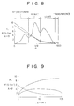
- FIG.8 is a graph illustrating an example of a variation of an enhancement coefficient.
- FIG.9 is a graph illustrating an example of an enhancement coefficient varying in accordance with (S-S m ).
- FIGS.10 and 11 are flow charts illustrating examples of an image processing.
- FIG.12 is a graph illustrating a sensitive curve of and X-ray film.
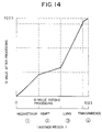
- FIGS.13 and 14 are graphs illustrating a gradational curve in an X-ray photograph.
- FIG.15 is a diagram illustrating a thorax X-ray photograph and image data for one line on the thorax X-ray photograph.
- FIGS.16 and 17 are flow charts illustrating examples of a gradational processing.
- a digital image is obtained from a thorax X-ray photograph.
- the X-ray hardly transmits through the centrum and, and can easily transmit through the lung region.
- Transmittance of X-rays in the heart region is intermediate between those of the centrum and lung region, A transparent region corresponding to empty space has the largest X-ray transmittance.
- the image data of each pixel included in a region having a small X-ray transmittance is small.
- the image data of each pixel included in a region having a large X-ray transmittance is large.
- a histogram of image data in a thorax X-ray photograph is formed as shown in FIG.6.
- the image data has a value falling within a range of 0 - 1023 (1024 steps).
- the four peaks correspond respectively, from the left, to a first region including the centrum, a second region including the heart, a third region including the lung and a fourth region including the transparent region.
- each valley in the histogram when each valley in the histogram is detected, a relationship between the image data of each pixel and each tissue (region) is found in the histogram.
- each valley in a graph can be obtained based on a primary differentiation.
- a process for smoothing the histogram curve is required for detecting the valleys in the histogram.
- the process for smoothing the histogram curve is carried out in accordance with, for example, a moving average method.
- An average of frequencies of image data having values in a range of 0 - 20 is defined to as "11".
- An average of frequencies of image data having values in a range of 1 - 21 is defined to as "12".
- each average of frequencies of image data having values in the given range is determined.
- the range of values of image data used for obtaining each average is set so as to include a number of minute variations in the histogram curve falling within a rage of 2-10. In a case where the number of minute variations included in the range of values of image data in the histogram is equal to or less than 2, the histogram curve can not be effectively smoothed.
- the number of minute variations included in the range of values of image data in the histogram is equal to or greater than 10, valleys in the histogram curve can be smoothed, so that it is hard to detect valleys.
- the range of values of the image data (the width of the moving average) can be experimentally set. It is preferable that the range of values of image data used for obtaining the average in the moving average method be with in a range of 1/200 - 1/20 of a total range of values of image data.
- the range of values of image data used for obtaining the average in the moving average method is referred to as a range of the moving average.
- the total range of values of image data corresponds to a width of the histogram shown in FIG.6 (e.g. 1024).
- the range of a moving average depends on the total range of values of the image data. That is, in a case where the total range of values of image data (the width of the histogram curve) is equal to 1024, the range of the moving average may be wide. However, in a case where the total range of values of image data is equal to 256, the range of the moving average must be narrow. In this case, if the range of the moving average is wide, low frequency components in the histogram curve are eliminated.
- a histogram curve shown in FIG.7 is obtained. Valleys each corresponding to a point at which a differential value is equal to zero is found on the histogram curve.
- the histogram curve has three valleys. When the number of valleys found in the histogram is greater than three, the smoothing process using a new range of the moving average is carried out again. The new range of the moving average is greater than the previous range. For example, when seven valleys are found in the histogram curve obtained by a smoothing process using a range "20" of the moving average, the smoothing process using a range "30" of the moving average is carried out again.
- the histogram, corresponding to a thorax X-ray photograph, shown in FIG.6 has four peaks and three valleys. While the smoothing process (the moving average) is carried out, the borders are found.
- the range of the moving average used in the smoothing process is moved from a starting value of imagedata toward a small value.
- the start value is set at a value falling within a region of 85-90% of the maximum value (e.g. 1024).
- a difference between a minimum frequency and a maximum frequency in a range of the moving average is greater than a first reference, a value of image data corresponding to the minimum frequency is detected as a first border B1.
- the first reference is set to a value in a range of 1/10000 - 10/10000 of the total number of frequency included in the histogram.
- a pixel having a value greater than the first border is included in an image region corresponding to a transparent region which is not an anatomical region or an anatomical region around the ribs. Further, the range of the moving average is moved toward a small value of image data.
- a maximum frequency is detected as a first peak P1 in the histogram under a condition in which there exists no valley greater than a second reference is detected as a first peak P1.
- the second reference is set at a value falling within a range of 1/10000 - 5/10000 of the total frequencies included in the histogram.
- a value of image data corresponding to the selected frequency is detected as a second border B2.
- the second border normally corresponds to a border between the lung region and the heart-diaphragm region. After this, a second peak P2 is detected in the same manner as the first peak P1. Then if a difference between a selected frequency and the second peak P2 is greater than a third reference, a value of image data corresponding to the selected frequency is detected as a third border B3.
- the third reference is set to a value falling within a range of 5/10000 - 10/10000 of the total frequencies included in the histogram.
- the third border B3 corresponds to a border between a part of the lung behind the heart and the centrum.
- an image on the X-ray photograph is divided into four image regions corresponding to the anatomical regions.
- the first image region has pixels each having a value of image data less than the third border B3
- the second image region has pixels each having a value of image data between the third border B3 and the second border B2
- the third image region has pixels each having a value of image data between the second border B2 and the first border B1
- the fourth image region has pixels each having a value of image data greater than the first border B1.
- the first image region corresponds to the mediastinum
- the second image region corresponds to the heart-diaphragm region
- the third image region corresponds to the lung region
- the fourth image region corresponds to the transparent region.
- a spatial frequency processing is applied to each anatomical region detected in the X-ray photograph in accordance with the above process.
- a degree of enhancement with respect to image data of each pixel included in the lung region in the X-ray photograph is slightly minute or zero.
- a degree of enhancement with respect to image data each pixel included in the centrum, the diaphragm and the heart region in the X-ray photograph is large.
- the enhancement coefficient K is set to a value falling within a range of 1.0 - 10.0 in the centrum.
- the enhancement coefficient K is set to a value falling within a range of 0.7 - 7.0.
- the enhancement coefficient K is set to a value falling within a range of 0 - 1.5.
- a relationship between the enhancement coefficient K and the values of the image data is represented by a monotone decreasing curve or a monotone increasing curve (inverse brightness), as shown in FIG.8.
- the monotone decreasing or increasing curve can have a constant value with respect to the values of the image data.
- the enhancement coefficient K is represented by f(S-S m ).
- Values of the enhancement coefficient K can be obtained with reference to a look-up table made in accordance with a function f(S-S m ).
- the function f( ⁇ S) is defined, for example, as follows.
- This monotone increasing function may have a section which has a constant value with respect to values of ⁇ S.
- the function f( ⁇ S) is a monotone decreasing function in which a value (K) of the function f( ⁇ S) monotonously decreases when ⁇ S increases.
- the monotone decreasing function may have a section which has a constant value with respect to values of ⁇ S.
- the enhancement coefficient K is varied based on a standard deviation ⁇ of a value of each of pixels in the unsharp mask.
- the standard deviation ⁇ is large, the enhancement coefficient is set to a small value to prevent noises from being enhanced.
- a size of the unsharp mask be varied based on a size of an image region corresponding to each anatomical region. That is, a unsharp mask having a large size is used in image regions corresponding to the a mediastinum, and a unsharp mask having a small size is used in an image region corresponding to the heart-diaphragm region and the lung region.
- the size of the unsharp mask used in the image regions corresponding to the mediastinum is set to a value falling within a range of 4-8 mm
- the size of the unsharp mask used in the image regions corresponding to the heart-diaphragm region and the lung region is set to a value falling within a range of 3-5 mm.
- an image of a thorax X-ray photograph stored in a photostimulable phosphor is read out, in step 200.
- the image read out from the photostimulable phosphor is stored, as digital image data, in a memory, in step 201.
- the image data is read out from the memory line by line, and a sequence of values of image data of pixels in one line is formed, in step 202.
- a smoothing process (the moving average method) is applied to the sequence of values of the image data for one line, in step 203.
- a primary differentiation processing is applied to the smoothed sequence of values of image data obtained by step 203, in step 204.
- step 205 maximum points and minimum points on the smoothed sequence of values of image data for one line are detected based on the result obtained by step 204, in step 205.
- a border pixel on each border between adjacent tissues (the anatomical regions) is determined by using the maximum points and the minimum points.
- An image region corresponding to each anatomical region is determined based on the border pixels in all lines of the image data stored in the memory.
- a spatial frequency processing is applied to the image stored in the memory, in step 207.
- the spatial frequency processing is carried out in accordance with either the formula (1), (2) or (3), and the enhancement coefficient used in the spatial frequency processing is varied in accordance with the image regions corresponding to the anatomical regions, as shown in FIG.8 or FIG.9.
- an image of a thorax X-ray photograph stored in a photostimulable phosphor is read out, in step 300.
- the image read out from the photostimulable phosphor is stored, as digital image data, in a memory, in step 301.
- a histogram of values of image data stored in the memory is made, as shown in FIG.6, in step 302.
- a smoothing process (the moving average method) is applied to the histogram curve obtained by step 302.
- a primary differentiation processing is applied to the smoothed histogram curve obtained as shown in FIG.7 by stop 303.
- Each border point at which a primary differential value is changed from positive to negative is detected based on the result obtained by step 304, in step 305.
- An value of the image data of a pixel corresponding to each border point on the smoothed histogram curve is defined as a border value.
- Each border pixel having the border value is detected from pixels in one line, in step 306.
- Step 306 is repeatedly carried out for all lines of the image data stored in the memory, so that border pixels for all lines of the image data are stored in the memory, in step 307.
- Each of the border pixels is located on a border between image regions corresponding to adjacent anatomical regions.
- An image region corresponding to each anatomical region is determined based on the border pixels in all lines of the image stored in the memory.
- a spatial frequency processing is applied to the image data stored in the memory, in step 308, in the same manner as that in step 207 shown in FIG.10.
- the enhancement coefficient used in the spatial frequency processing is varied in accordance with the image regions corresponding to the anatomical regions, as shown in FIG.8 or FIG.9.
- a predetermined gradational processing is applied to the image data, the image corresponding to the X-ray photograph is displayed in a CRT or printed on a silver film (steps 208, 209, 210 and 211 in FIG.10, and steps 309, 310, 311 and 312 in FIG.11).
- a gradational curve representing a relationship between values of input and output data is applied to an image region corresponding to each anatomical region. Gradational curves applied to image regions corresponding to the anatomical regions differ from each other so that an output image in which a gradational property is improved is obtained.
- a conventional X-ray film has a sensitivity with respect to transmittance of X-ray shown in FIG.12.
- a gradational curve applied to each anatomical region differ from that applied to other anatomical region, as shown in FIGS.13 and 14.
- the gradational curves shown in FIG.13 are not continuous. That is, when the gradational processing is carried out in accordance with the gradational curves shown in FIG.13, two output values corresponding to one input value can be obtained for each border between image regions corresponding to adjacent anatomical regions.
- a contrast of density in each of images corresponding to the centrum, the diaphragm region and the hear region is poor.
- the gradational curves, shown in FIGS.13 and 14, are made so that a range of density representing each of images corresponding to the centrum and the diaphragm region is increased in order to improve the contrast of density in each of the images. Further, a level of the density in an image corresponding to the hear region is increased. As the range of density representing each of the images corresponding to the centrum and the diaphragm region is increased, a range of density representing an image corresponding to the lung region is decreased.
- an image having an improved balance of density can be obtained. That is, the image corresponding to the lung region is fine, and a thoracic vertebrae and vascular tracts are shown in the images corresponding to the heart-diaphragm region and the mediastinum. Thus, a thorax image in which diseases in each anatomical region can be easily found can be obtained.
- values of image data for one line (L) vary as shown in FIG.15.
- Each value of image data corresponds to X-ray transmittance.
- a pixel in an image region corresponding to an anatomical region having a large X-ray transmittance has a large value of image data.
- a pixel in an image region corresponding to a transparent region which is not an anatomical region has a maximum value of image data.
- a pixel in an image region corresponding to an anatomical region around the ribs has a small value of image data.
- a pixel in an image region corresponding to the lung region has a large value of image data.
- a pixel in an image region corresponding to the mediastinum has a value less than that in the image region corresponding to the lung region.
- An anatomical region corresponding to an image region to which a pixel belongs can be easily determined based on a value of the image data of the pixel, with reference to a curve representing image data for one line shown in FIG.15.
- FIG.16 shows a third embodiment of the image processing.
- steps 400 through 407 are carried out in the same manner as steps 300 through 307 shown in FIG.11, so that an image region corresponding to each anatomical region is determined based on the border pixels in all lines of the image stored in the memory.
- a gradational processing is applied to the image data stored in the memory, in step 407.
- the gradational processing is carried out with reference to a look-up table (420) storing the gradational curves shown in FIG.13 or 14. That is, a gradational curve used in the gradational processing is varied in accordance with the image regions corresponding to the anatomical regions, as shown in FIG.13 or FIG.14.
- FIG.17 shows a fourth embodiment of the image processing.
- steps 500 through 506 are carried out in the same manner as steps 200 through 206 shown in FIG.10, so that an image region corresponding to each anatomical region is determined based on the border pixels in all lines of the image stored in the memory.
- a gradational processing is applied to the image data stored in the memory with reference to a look-up table (520) storing the gradational curves shown in FIG.13 or 14, in step 507. Then the gradational processing is carried out in the same manner as those in step 407 shown in FIG.16.
- the image data obtained in the gradational processing is displayed in a CRT or printed on a silver film (steps 409 and 410 shown in FIG.16, and steps 508 and 509 shown in FIG.17).
- the image data can be sampled at a ratio of one to 4 or one to 64 pixels.
Landscapes
- General Physics & Mathematics (AREA)
- Engineering & Computer Science (AREA)
- Physics & Mathematics (AREA)
- Theoretical Computer Science (AREA)
- Health & Medical Sciences (AREA)
- Life Sciences & Earth Sciences (AREA)
- Molecular Biology (AREA)
- Multimedia (AREA)
- Spectroscopy & Molecular Physics (AREA)
- Signal Processing (AREA)
- High Energy & Nuclear Physics (AREA)
- Image Analysis (AREA)
- Image Processing (AREA)
- Apparatus For Radiation Diagnosis (AREA)
Applications Claiming Priority (2)
| Application Number | Priority Date | Filing Date | Title |
|---|---|---|---|
| JP3093152A JPH04303427A (ja) | 1991-03-30 | 1991-03-30 | 放射線画像処理方法および放射線画像処理装置 |
| JP93152/91 | 1991-03-30 |
Publications (3)
| Publication Number | Publication Date |
|---|---|
| EP0507485A2 true EP0507485A2 (fr) | 1992-10-07 |
| EP0507485A3 EP0507485A3 (en) | 1993-10-13 |
| EP0507485B1 EP0507485B1 (fr) | 1998-12-02 |
Family
ID=14074570
Family Applications (1)
| Application Number | Title | Priority Date | Filing Date |
|---|---|---|---|
| EP92302496A Expired - Lifetime EP0507485B1 (fr) | 1991-03-30 | 1992-03-24 | Procédé et appareil pour le traitement d'images correspondant à des échantillons radiographiques |
Country Status (4)
| Country | Link |
|---|---|
| US (1) | US5345513A (fr) |
| EP (1) | EP0507485B1 (fr) |
| JP (1) | JPH04303427A (fr) |
| DE (1) | DE69227721T2 (fr) |
Cited By (3)
| Publication number | Priority date | Publication date | Assignee | Title |
|---|---|---|---|---|
| EP0726060A3 (fr) * | 1995-01-23 | 1996-11-13 | Fuji Photo Film Co Ltd | Dispositif pour la diagnose à ordinateur d'images |
| EP0993182A3 (fr) * | 1998-08-26 | 2002-06-12 | Fuji Photo Film Co., Ltd. | Système de prise d'image de radiation |
| DE102004008979A1 (de) * | 2004-02-24 | 2005-09-29 | Siemens Ag | Verfahren zur Filterung tomographischer 3D-Darstellungen nach erfolgter Rekonstruktion von Volumendaten |
Families Citing this family (23)
| Publication number | Priority date | Publication date | Assignee | Title |
|---|---|---|---|---|
| JP3467285B2 (ja) * | 1993-04-02 | 2003-11-17 | コニカミノルタホールディングス株式会社 | 放射線画像処理方法 |
| JP3342742B2 (ja) * | 1993-04-22 | 2002-11-11 | 株式会社日立メディコ | 画像処理装置 |
| US5400377A (en) * | 1993-07-16 | 1995-03-21 | General Electric Company | Artifact reduction method for tomographic image reconstruction using cross-plane rays |
| US5638458A (en) * | 1993-11-30 | 1997-06-10 | Arch Development Corporation | Automated method and system for the detection of gross abnormalities and asymmetries in chest images |
| JP3490490B2 (ja) * | 1994-01-28 | 2004-01-26 | 株式会社東芝 | パターン画像処理装置及び画像処理方法 |
| US5889882A (en) * | 1996-03-21 | 1999-03-30 | Eastman Kodak Company | Detection of skin-line transition in digital medical imaging |
| NL1006420C2 (nl) * | 1997-06-27 | 1998-12-29 | Optische Ind Oede Oude Delftoe | Werkwijze en inrichting voor de weergave van beelden. |
| US6292596B1 (en) | 1997-09-19 | 2001-09-18 | Eastman Kodak Company | Method for automatic image dependent digitization and processing of small format films |
| US5943435A (en) * | 1997-10-07 | 1999-08-24 | Eastman Kodak Company | Body part recognition in radiographic images |
| US6195474B1 (en) | 1997-10-28 | 2001-02-27 | Eastman Kodak Company | Pathology dependent viewing of processed dental radiographic film having authentication data |
| US6257363B1 (en) * | 1997-12-16 | 2001-07-10 | Nsk Ltd. | Automotive passenger restraint and protection apparatus |
| US6850634B1 (en) * | 1998-09-25 | 2005-02-01 | Canon Kabushiki Kaisha | Image processing apparatus, method, and storage medium for processing a radiation image |
| US20020085743A1 (en) * | 2000-04-04 | 2002-07-04 | Konica Corporation | Image processing selecting method, image selecting method and image processing apparatus |
| DE10020258A1 (de) * | 2000-04-25 | 2001-11-08 | Siemens Ag | Verfahren zum Betrieb eines CT-Gerätes |
| JP4690204B2 (ja) * | 2006-01-16 | 2011-06-01 | 富士フイルム株式会社 | 画像再生装置およびそのプログラム |
| US7448008B2 (en) * | 2006-08-29 | 2008-11-04 | International Business Machines Corporation | Method, system, and program product for automated verification of gating logic using formal verification |
| US7448018B2 (en) * | 2006-09-12 | 2008-11-04 | International Business Machines Corporation | System and method for employing patterning process statistics for ground rules waivers and optimization |
| JP5305715B2 (ja) * | 2008-04-04 | 2013-10-02 | 富士フイルム株式会社 | 放射線画像処理装置 |
| US8320385B1 (en) | 2008-10-31 | 2012-11-27 | Sprint Communications Company L.P. | Wireless scheduler bandwidth estimation for quick start |
| JP5534840B2 (ja) * | 2010-02-03 | 2014-07-02 | キヤノン株式会社 | 画像処理装置、画像処理方法、画像処理システム及びプログラム |
| JP5579639B2 (ja) * | 2011-02-26 | 2014-08-27 | ジーイー・メディカル・システムズ・グローバル・テクノロジー・カンパニー・エルエルシー | 画像処理装置およびプログラム並びに画像診断装置 |
| JP5686661B2 (ja) * | 2011-04-27 | 2015-03-18 | 株式会社日立メディコ | X線撮影装置 |
| KR101750173B1 (ko) * | 2015-10-16 | 2017-06-22 | 국립암센터 | 방사선 유효 피폭량 자동 계산 시스템 및 방법 |
Family Cites Families (13)
| Publication number | Priority date | Publication date | Assignee | Title |
|---|---|---|---|---|
| US3859527A (en) * | 1973-01-02 | 1975-01-07 | Eastman Kodak Co | Apparatus and method for producing images corresponding to patterns of high energy radiation |
| JPS5588740A (en) * | 1978-12-26 | 1980-07-04 | Fuji Photo Film Co Ltd | Method of treating gradation of radiation picture of breast and its device |
| JPS60171573A (ja) * | 1984-02-17 | 1985-09-05 | Hitachi Ltd | 画像処理システムにおける画像強調方式 |
| JPH0622497B2 (ja) * | 1984-07-24 | 1994-03-30 | 株式会社島津製作所 | 医用画像表示装置 |
| JPS6135069A (ja) * | 1984-07-26 | 1986-02-19 | Fuji Photo Film Co Ltd | 放射線画像情報再生方法 |
| US4950894A (en) * | 1985-01-25 | 1990-08-21 | Fuji Photo Film Co., Ltd. | Radiation image read-out method |
| JPS62115969A (ja) * | 1986-10-15 | 1987-05-27 | Fuji Photo Film Co Ltd | 照射野認識方法 |
| JPS63133762A (ja) * | 1986-11-25 | 1988-06-06 | Fuji Photo Film Co Ltd | 照射野認識方法および画像処理条件決定方法 |
| JPH0671300B2 (ja) * | 1987-03-20 | 1994-09-07 | 富士写真フイルム株式会社 | 放射線画像情報の読取処理条件決定装置 |
| JPH0642882B2 (ja) * | 1987-04-20 | 1994-06-08 | 富士写真フイルム株式会社 | 所望画像信号範囲決定方法 |
| JPH083843B2 (ja) * | 1988-03-18 | 1996-01-17 | 富士写真フイルム株式会社 | 放射線画像読取装置 |
| JPH01256935A (ja) * | 1988-04-06 | 1989-10-13 | Hitachi Ltd | Crt診断用画像処理方式 |
| JPH04141154A (ja) * | 1990-10-03 | 1992-05-14 | Konica Corp | 放射線画像処理装置 |
-
1991
- 1991-03-30 JP JP3093152A patent/JPH04303427A/ja active Pending
-
1992
- 1992-03-24 DE DE69227721T patent/DE69227721T2/de not_active Expired - Fee Related
- 1992-03-24 US US07/856,993 patent/US5345513A/en not_active Expired - Lifetime
- 1992-03-24 EP EP92302496A patent/EP0507485B1/fr not_active Expired - Lifetime
Cited By (6)
| Publication number | Priority date | Publication date | Assignee | Title |
|---|---|---|---|---|
| EP0726060A3 (fr) * | 1995-01-23 | 1996-11-13 | Fuji Photo Film Co Ltd | Dispositif pour la diagnose à ordinateur d'images |
| US5761334A (en) * | 1995-01-23 | 1998-06-02 | Fuji Photo Film Co.,Ltd. | Apparatus for computer aided diagnosis of medical images having abnormal patterns |
| EP0993182A3 (fr) * | 1998-08-26 | 2002-06-12 | Fuji Photo Film Co., Ltd. | Système de prise d'image de radiation |
| DE102004008979A1 (de) * | 2004-02-24 | 2005-09-29 | Siemens Ag | Verfahren zur Filterung tomographischer 3D-Darstellungen nach erfolgter Rekonstruktion von Volumendaten |
| DE102004008979B4 (de) * | 2004-02-24 | 2006-12-28 | Siemens Ag | Verfahren zur Filterung tomographischer 3D-Darstellungen nach erfolgter Rekonstruktion von Volumendaten |
| US7650023B2 (en) | 2004-02-24 | 2010-01-19 | Siemens Aktiengeśellschaft | Method for filtering tomographic 3D images after completed reconstruction of volume data |
Also Published As
| Publication number | Publication date |
|---|---|
| JPH04303427A (ja) | 1992-10-27 |
| US5345513A (en) | 1994-09-06 |
| DE69227721T2 (de) | 1999-04-22 |
| DE69227721D1 (de) | 1999-01-14 |
| EP0507485A3 (en) | 1993-10-13 |
| EP0507485B1 (fr) | 1998-12-02 |
Similar Documents
| Publication | Publication Date | Title |
|---|---|---|
| US5345513A (en) | Method and apparatus for processing image corresponding to radiographic pattern | |
| US4317179A (en) | Method and apparatus for processing a radiographic image | |
| US4310886A (en) | Image gradation processing method and apparatus for radiation image recording system | |
| EP0031952B1 (fr) | Procédé et appareil pour traiter une image radiographique | |
| US4315318A (en) | Method and apparatus for processing a radiation image | |
| EP0643534B1 (fr) | Procédé de traitement d'image de rayonnement par soustraction d'énergie | |
| US20070009145A1 (en) | Balancing areas of varying density in a digital image | |
| US4903205A (en) | Method and apparatus for displaying radiation image, and method and apparatus for calculating unsharp mask signal used for the same | |
| US5369572A (en) | Radiographic image processing method wherein small variation of density is selectively made clear | |
| US5210415A (en) | Method and apparatus for forming energy subtraction images | |
| US6075877A (en) | Method and apparatus of image processing using energy substraction parameters according to thickness of an object | |
| US6125166A (en) | Method of forming energy subtraction images | |
| US5291403A (en) | Method of and apparatus for processing radiation image | |
| US5796870A (en) | Method and apparatus for compressing dynamic ranges of images | |
| US5714764A (en) | Method for detecting prospective abnormal patterns | |
| US6466689B1 (en) | Method and system for digital radiography | |
| US5272339A (en) | Method for adjusting conditions in radiation image recording, readout, and reproducing systems | |
| US4306290A (en) | Image gradation processing method and apparatus for radiographic image copying system | |
| US5115476A (en) | Edge finding method and apparatus | |
| JPH0326238A (ja) | 放射線画像診断装置 | |
| US20020136441A1 (en) | Energy subtraction processing method and apparatus | |
| US5633509A (en) | Energy subtraction processing method and apparatus | |
| JPS6139573Y2 (fr) | ||
| JPH05252444A (ja) | 放射線画像処理方法 | |
| JPH07255012A (ja) | 放射線画像処理装置 |
Legal Events
| Date | Code | Title | Description |
|---|---|---|---|
| PUAI | Public reference made under article 153(3) epc to a published international application that has entered the european phase |
Free format text: ORIGINAL CODE: 0009012 |
|
| AK | Designated contracting states |
Kind code of ref document: A2 Designated state(s): DE FR GB |
|
| PUAL | Search report despatched |
Free format text: ORIGINAL CODE: 0009013 |
|
| AK | Designated contracting states |
Kind code of ref document: A3 Designated state(s): DE FR GB |
|
| 17P | Request for examination filed |
Effective date: 19931217 |
|
| 17Q | First examination report despatched |
Effective date: 19960528 |
|
| GRAG | Despatch of communication of intention to grant |
Free format text: ORIGINAL CODE: EPIDOS AGRA |
|
| GRAG | Despatch of communication of intention to grant |
Free format text: ORIGINAL CODE: EPIDOS AGRA |
|
| GRAH | Despatch of communication of intention to grant a patent |
Free format text: ORIGINAL CODE: EPIDOS IGRA |
|
| RBV | Designated contracting states (corrected) |
Designated state(s): DE |
|
| GRAH | Despatch of communication of intention to grant a patent |
Free format text: ORIGINAL CODE: EPIDOS IGRA |
|
| GRAA | (expected) grant |
Free format text: ORIGINAL CODE: 0009210 |
|
| AK | Designated contracting states |
Kind code of ref document: B1 Designated state(s): DE |
|
| REF | Corresponds to: |
Ref document number: 69227721 Country of ref document: DE Date of ref document: 19990114 |
|
| PLBE | No opposition filed within time limit |
Free format text: ORIGINAL CODE: 0009261 |
|
| 26N | No opposition filed | ||
| PGFP | Annual fee paid to national office [announced via postgrant information from national office to epo] |
Ref country code: DE Payment date: 20080407 Year of fee payment: 17 |
|
| PG25 | Lapsed in a contracting state [announced via postgrant information from national office to epo] |
Ref country code: DE Free format text: LAPSE BECAUSE OF NON-PAYMENT OF DUE FEES Effective date: 20091001 |