EP0507529A1 - Dispositif d'indication d'échelle pour instrument de mesure à composants électroniques tel qu'un compteur de temps - Google Patents
Dispositif d'indication d'échelle pour instrument de mesure à composants électroniques tel qu'un compteur de temps Download PDFInfo
- Publication number
- EP0507529A1 EP0507529A1 EP92302775A EP92302775A EP0507529A1 EP 0507529 A1 EP0507529 A1 EP 0507529A1 EP 92302775 A EP92302775 A EP 92302775A EP 92302775 A EP92302775 A EP 92302775A EP 0507529 A1 EP0507529 A1 EP 0507529A1
- Authority
- EP
- European Patent Office
- Prior art keywords
- scale
- plate
- characters
- gear
- character plate
- Prior art date
- Legal status (The legal status is an assumption and is not a legal conclusion. Google has not performed a legal analysis and makes no representation as to the accuracy of the status listed.)
- Granted
Links
- 238000003780 insertion Methods 0.000 description 2
- 230000037431 insertion Effects 0.000 description 2
- 230000003247 decreasing effect Effects 0.000 description 1
- 238000003908 quality control method Methods 0.000 description 1
Images


Classifications
-
- G—PHYSICS
- G04—HOROLOGY
- G04C—ELECTROMECHANICAL CLOCKS OR WATCHES
- G04C19/00—Producing optical time signals at prefixed times by electric means
- G04C19/04—Producing optical time signals at prefixed times by electric means by indicating members moved electrically, e.g. flap, band
-
- G—PHYSICS
- G04—HOROLOGY
- G04F—TIME-INTERVAL MEASURING
- G04F3/00—Apparatus which can be set and started to measure-off predetermined or adjustably-fixed time intervals with driving mechanisms, e.g. dosimeters with clockwork
- G04F3/06—Apparatus which can be set and started to measure-off predetermined or adjustably-fixed time intervals with driving mechanisms, e.g. dosimeters with clockwork with electric driving mechanisms
-
- G—PHYSICS
- G01—MEASURING; TESTING
- G01D—MEASURING NOT SPECIALLY ADAPTED FOR A SPECIFIC VARIABLE; ARRANGEMENTS FOR MEASURING TWO OR MORE VARIABLES NOT COVERED IN A SINGLE OTHER SUBCLASS; TARIFF METERING APPARATUS; MEASURING OR TESTING NOT OTHERWISE PROVIDED FOR
- G01D13/00—Component parts of indicators for measuring arrangements not specially adapted for a specific variable
- G01D13/02—Scales; Dials
- G01D13/04—Construction
- G01D13/10—Construction with adjustable scales; with auxiliary scales, e.g. vernier
-
- G—PHYSICS
- G04—HOROLOGY
- G04B—MECHANICALLY-DRIVEN CLOCKS OR WATCHES; MECHANICAL PARTS OF CLOCKS OR WATCHES IN GENERAL; TIME PIECES USING THE POSITION OF THE SUN, MOON OR STARS
- G04B19/00—Indicating the time by visual means
- G04B19/06—Dials
- G04B19/16—Shiftable dials, e.g. indicating alternately from 1 to 12 and from 13 to 24
-
- Y—GENERAL TAGGING OF NEW TECHNOLOGICAL DEVELOPMENTS; GENERAL TAGGING OF CROSS-SECTIONAL TECHNOLOGIES SPANNING OVER SEVERAL SECTIONS OF THE IPC; TECHNICAL SUBJECTS COVERED BY FORMER USPC CROSS-REFERENCE ART COLLECTIONS [XRACs] AND DIGESTS
- Y10—TECHNICAL SUBJECTS COVERED BY FORMER USPC
- Y10S—TECHNICAL SUBJECTS COVERED BY FORMER USPC CROSS-REFERENCE ART COLLECTIONS [XRACs] AND DIGESTS
- Y10S116/00—Signals and indicators
- Y10S116/47—Scale conversion, e.g. english-metric
Definitions
- This invention relates to a scale indication device for electronic components. More particularly, the invention relates to a driving mechanism and a character plate for changing the indicated scale on a meter of an electronic component such as a timer.
- the device described in 2-7838 is illustrated in prior art Figures 7 and 8.
- six sets of numerals 2 for time display are printed on one side of display gear 1, which consists of a doughnut-shaped plate.
- the display gear 1 is rotatable about its axis, which is also the axis of dial 8, by gear 3.
- This causes the time display numerals 2 to appear sequentially in display window 6a, which is one of the display windows 6 in scale panel 5 on the face of timer 4.
- the numerals might appear in the sequence "8,” "4,” “0.8,” “0.4.”
- the rotation of gear 1 causes the numerals on the scale to change.
- Gear 7 is the input gear which causes display gear 1 to rotate.
- time display numerals 2 correspond perfectly to each of the display windows 6 on scale plate 5, they must be printed at a slight inclination which matches the angle of rotation of display gear 1. This requires a large amount of time and labor in the design phase and in quality control since it necessitates a high degree of accuracy in the printing of the time display numerals 2.
- the device described in 63-10819 overcomes the problem of size and inclination of the characters by using an extremely complex gear system to move the character plate in a non-concentric fashion.
- the 63-10819 device requires "two-sided" assembly (i.e., the gears system requires assembly from both the front and the rear), thus requiring that the device be fully assembled prior to connection to other components.
- This is a disadvantage as it may be desirable to assemble the scale indication device from the front side only after the back portion has been attached, for instance, to a circuit board.
- the device of the invention comprises a character plate having a plurality of sets of characters printed on a front side thereof, each said set of characters comprising a plurality of characters arranged about an eccentric circle having a predetermined radius; a scale plate disposed adjacent said character plate, said scale plate having a window corresponding to each of said plurality of sets of characters such that only one of said characters in each set may be viewed through the window at a time; and eccentric rotation means mounted on a gearbox for rotating said character plate such that different ones of said characters in each set may be viewed through the window, said means comprising: a scale switching gear rotatable about an axis, first engagement means formed on the scale switching gear at a distance from the axis equal to the predetermined radius, and second engagement means formed on the character plate for rotatably engaging said first engagement means.
- the gear mechanism of the preferred embodiment is constructed in the following way. It has, either on the scale switching gear in this gear mechanism or on the back side of the numbered plate, a small projection which is eccentric by a specified distance with respect to the rotating shaft of the scale switching gear. It has a small hole to engage this projection on the plate or gear, whichever is opposite to the projection, which hole can rotate around the said eccentric projection. Further it has, either on the front side of the gearbox which faces the numbered plate or on the back side of the plate which faces the gearbox, annular guides with radii equal to the distance by which the aforesaid eccentric projection is off center.
- a scale switching gear is made to rotate as the scale is being set.
- every part of a numbered plate which is interlocked with this scale switching gear rotates eccentrically describing an arc of a circle whose radius is equal to the eccentricity of the eccentric projection.
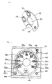
- the indicator device includes a gearbox 10, a gear mechanism 20, numbered plate 30, and scale plate 40.
- gearbox 10 In the center of gearbox 10 is a cylindrical projection 12. In the center of this projection is a hole 11, into which a shaft (not pictured) of dial 50 ( Figure 3) is inserted. In the cutaway segment 13 at the corner of gearbox 10 are insertion holes 14 and 15, into which an input gear 21 (to be described below) and scale switching gear 23 are rotatably fitted. Two guide pins 16 and 17 are provided in the appropriate places.
- the indicator needle 51 shown in Figure 3 is joined to dial 50 and rotates along with it.
- Gear mechanism 20 comprises input gear 21 and scale switching gear 23.
- On the projecting surface of input gear 21 is a slot 22, into which a screwdriver can be inserted to rotate the gear.
- Input gear 21 is fitted into insertion hole 14 on gearbox 10 so as to be able to rotate.
- Scale switching gear 23 rotates as a result of being meshed with the input gear 21.
- the contactor on the lower surface of gear 23 makes contact with the scale-setting pattern in order to switch the scale of the limit time.
- Eccentric projection 24, which is made with the gear as a single piece, is eccentric with respect to the axis of rotation by a distance r (see Figure 5).
- Scale switching gear 23 fits into hole 15 in the gearbox 10 so as to be able to rotate.
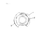
- Numbered plate 30 consists of a nearly doughnutshaped plate with a portion 31 cut out.
- On the surface of plate 30 are printed seven sets of time display numerals (32a through 32g), with four numerals in each set (see Figure 14).
- Numerals 32a through 32g are arranged along the circumference of circles whose radii are equal to the eccentricity r of eccentric projection 24.
- Annular guides 34 and 35 are provided to engage, respectively, guidepins 16 and 17 on the gearbox 10. The radii of guides 34 and 35 are identical to eccentricity r.
- Numbered plate 30 is mounted on gearbox 10, and eccentric projection 24 fits into its hole 33.
- cylindrical projection 12 on gearbox 10 fits easily into center hole 36 in numbered plate 30, and the back of numbered plate 30 and the outer surface of cylindrical projection 12 are in virtually the same plane.
- Scale plate 40 is made from a virtually square plate which can be mounted on the gearbox 10. In the center of the plate is a hole 41, into which the shaft of dial 50 is inserted. Scale gradations 42 radiate from this center. Adjacent to these scale gradations 42 are provided display windows 43a through 43g, which correspond to the sets of time display numerals 32a through 32g. In one corner of scale plate 40 is adjustment hole 44, through which the input gear 21 can rotate in order to switch the time display numerals (4 modes in this embodiment).
- 45 indicates the adjustment hole to switch the time scale; 46 indicates the display window for time increments; 47 is the adjustment hole to switch operating modes; and 48 is the display window for operating mode.
- each set of time display numerals 32a through 32g rotates eccentrically, and the numerals are exposed, one at a time, through display windows 43a through 43g. In this way the numerals for the scale gradations are changed.
- the scale indication device of the invention requires a small number of components and can be easily assembled.
- the device can be assembled even when the back of the gearbox is already mounted to an electrical component.
- the depth necessary for the device is decreased, thus resulting in a low-profile package.
- the total frictional force is reduced and thus the scale can be changed without effort.
- the invention is not limited to the above-described embodiment.
- at least two annular guides should be provided on either the gearbox or the numbered plate, but three would also be acceptable.
- the guide pins may alternatively be provided on the numbered plate and the annular guides on the gearbox.
- the eccentric projection need not be provided on the scale switching gear; instead, a hole which is eccentric with respect to the axis of rotation may be provided on the scale switching gear, with the projection which engages the said hole in such a way as to be able to rotate provided on the numbered plate.
Landscapes
- Physics & Mathematics (AREA)
- General Physics & Mathematics (AREA)
- Measurement Of Predetermined Time Intervals (AREA)
- Electric Clocks (AREA)
- Length-Measuring Instruments Using Mechanical Means (AREA)
- Measurement Of Unknown Time Intervals (AREA)
- Details Of Measuring And Other Instruments (AREA)
- A Measuring Device Byusing Mechanical Method (AREA)
Applications Claiming Priority (2)
| Application Number | Priority Date | Filing Date | Title |
|---|---|---|---|
| JP06735491A JP3250228B2 (ja) | 1991-03-30 | 1991-03-30 | タイマの時間設定装置 |
| JP67354/91 | 1991-03-30 |
Publications (2)
| Publication Number | Publication Date |
|---|---|
| EP0507529A1 true EP0507529A1 (fr) | 1992-10-07 |
| EP0507529B1 EP0507529B1 (fr) | 1996-01-31 |
Family
ID=13342600
Family Applications (1)
| Application Number | Title | Priority Date | Filing Date |
|---|---|---|---|
| EP92302775A Expired - Lifetime EP0507529B1 (fr) | 1991-03-30 | 1992-03-30 | Dispositif d'indication d'échelle pour instrument de mesure à composants électroniques tel qu'un compteur de temps |
Country Status (8)
| Country | Link |
|---|---|
| US (1) | US5245944A (fr) |
| EP (1) | EP0507529B1 (fr) |
| JP (1) | JP3250228B2 (fr) |
| KR (1) | KR100194478B1 (fr) |
| AT (1) | ATE133800T1 (fr) |
| DE (1) | DE69207938T2 (fr) |
| DK (1) | DK0507529T3 (fr) |
| ES (1) | ES2085564T3 (fr) |
Families Citing this family (14)
| Publication number | Priority date | Publication date | Assignee | Title |
|---|---|---|---|---|
| JPH11306941A (ja) * | 1998-04-21 | 1999-11-05 | Matsushita Electric Works Ltd | マルチレンジタイマ |
| JP2002333768A (ja) * | 2001-05-11 | 2002-11-22 | Sharp Corp | 現像方法および画像形成装置 |
| US6718906B2 (en) * | 2002-06-03 | 2004-04-13 | Volvo Trucks North America, Inc. | Dual scale vehicle gauge |
| US7072246B2 (en) * | 2003-05-20 | 2006-07-04 | Timex Group B.V. | Wearable electronic device with multiple ring indicia display |
| US7347575B2 (en) * | 2004-07-13 | 2008-03-25 | Yazaki North America, Inc. | Vehicle gauge with embedded driver information |
| US7427143B1 (en) * | 2005-06-30 | 2008-09-23 | Yazaki North America, Inc. | Instrument cluster with three-dimensional display |
| US7750821B1 (en) | 2007-03-30 | 2010-07-06 | Yazaki North America, Inc. | System and method for instrument panel with color graphical display |
| US7571696B1 (en) | 2007-06-19 | 2009-08-11 | Yazaki North America, Inc. | System and method for analog vehicle gauge with embedded driver information |
| JP5109794B2 (ja) * | 2008-05-12 | 2012-12-26 | オムロン株式会社 | 電子タイマ |
| JP5583369B2 (ja) * | 2009-07-28 | 2014-09-03 | 日本電産サンキョー株式会社 | 媒体処理装置 |
| JP6003027B2 (ja) * | 2011-08-30 | 2016-10-05 | カシオ計算機株式会社 | 文字板構造及び腕時計 |
| US9612577B2 (en) * | 2013-04-22 | 2017-04-04 | Donald J. Lecher | Device displaying a series of sequential timekeeping periods |
| JP6110502B2 (ja) * | 2013-09-17 | 2017-04-05 | 矢崎総業株式会社 | 目盛構造および車両用計器 |
| US10596905B2 (en) * | 2017-01-02 | 2020-03-24 | Visteon Global Technologies, Inc. | Selective lighting for indicia |
Citations (3)
| Publication number | Priority date | Publication date | Assignee | Title |
|---|---|---|---|---|
| DE2942443A1 (de) * | 1979-10-20 | 1981-04-30 | Günter Dipl.-Phys. 3303 Vechelde Kramer | Anzeigeinstrument |
| GB2148557A (en) * | 1983-10-15 | 1985-05-30 | Junghans Gmbh Geb | Electromechanical short interval timer |
| US4974217A (en) * | 1989-04-04 | 1990-11-27 | Idec Izumi Corporation | Scale indicator used with electronic setting apparatus for setting numerical values of physical quantities or the like |
Family Cites Families (13)
| Publication number | Priority date | Publication date | Assignee | Title |
|---|---|---|---|---|
| US1427760A (en) * | 1915-09-27 | 1922-08-29 | Ridge Herman De Witt | Scale |
| US1362842A (en) * | 1920-02-12 | 1920-12-21 | Brown Sidney George | Gyro-compass |
| US2004724A (en) * | 1933-07-03 | 1935-06-11 | Erwin P Herzog | Measuring instrument |
| US2361563A (en) * | 1940-11-06 | 1944-10-31 | Montres Perret Et Berthoud Sa | Device for measuring time intervals |
| US2842091A (en) * | 1957-07-26 | 1958-07-08 | Ronald L Kennedy | True airspeed indicator |
| US3092072A (en) * | 1961-07-31 | 1963-06-04 | Tinius Olsen Testing Mach Co | Load indicating apparatus |
| DE1197815B (de) * | 1961-09-27 | 1965-07-29 | Arthur Droz | Tauch-Uhr |
| US3434453A (en) * | 1965-09-18 | 1969-03-25 | Hottinger Baldwin Mesztechnik | Indicating device |
| FR2097422A6 (fr) * | 1970-07-06 | 1972-03-03 | Honeywell Sa | |
| DE2218954C3 (de) * | 1972-04-19 | 1975-09-04 | Esge Elektrouhren Gmbh, 7442 Neuffen | Uhr mit 24-Stunden-Zlfferblatt |
| US4213089A (en) * | 1978-10-02 | 1980-07-15 | Tif Instruments, Inc. | Variable scale readout for multi-meter use |
| JP2572376B2 (ja) * | 1986-07-01 | 1997-01-16 | 松下電工株式会社 | タイマの時間設定装置 |
| CH676313B5 (fr) * | 1989-07-13 | 1991-07-15 | Breitling Montres Sa |
-
1991
- 1991-03-30 JP JP06735491A patent/JP3250228B2/ja not_active Expired - Lifetime
-
1992
- 1992-03-27 KR KR1019920005030A patent/KR100194478B1/ko not_active Expired - Lifetime
- 1992-03-30 DK DK92302775.9T patent/DK0507529T3/da active
- 1992-03-30 DE DE69207938T patent/DE69207938T2/de not_active Expired - Lifetime
- 1992-03-30 AT AT92302775T patent/ATE133800T1/de active
- 1992-03-30 ES ES92302775T patent/ES2085564T3/es not_active Expired - Lifetime
- 1992-03-30 US US07/858,996 patent/US5245944A/en not_active Expired - Lifetime
- 1992-03-30 EP EP92302775A patent/EP0507529B1/fr not_active Expired - Lifetime
Patent Citations (3)
| Publication number | Priority date | Publication date | Assignee | Title |
|---|---|---|---|---|
| DE2942443A1 (de) * | 1979-10-20 | 1981-04-30 | Günter Dipl.-Phys. 3303 Vechelde Kramer | Anzeigeinstrument |
| GB2148557A (en) * | 1983-10-15 | 1985-05-30 | Junghans Gmbh Geb | Electromechanical short interval timer |
| US4974217A (en) * | 1989-04-04 | 1990-11-27 | Idec Izumi Corporation | Scale indicator used with electronic setting apparatus for setting numerical values of physical quantities or the like |
Also Published As
| Publication number | Publication date |
|---|---|
| ES2085564T3 (es) | 1996-06-01 |
| EP0507529B1 (fr) | 1996-01-31 |
| JPH04303531A (ja) | 1992-10-27 |
| JP3250228B2 (ja) | 2002-01-28 |
| KR920018542A (ko) | 1992-10-22 |
| KR100194478B1 (ko) | 1999-06-15 |
| DE69207938D1 (de) | 1996-03-14 |
| US5245944A (en) | 1993-09-21 |
| DE69207938T2 (de) | 1996-08-14 |
| ATE133800T1 (de) | 1996-02-15 |
| DK0507529T3 (da) | 1996-06-10 |
Similar Documents
| Publication | Publication Date | Title |
|---|---|---|
| EP0507529B1 (fr) | Dispositif d'indication d'échelle pour instrument de mesure à composants électroniques tel qu'un compteur de temps | |
| US5819597A (en) | In-car rotation detecting apparatus | |
| US3621158A (en) | Electrical switching apparatus | |
| US5171978A (en) | Trackball assembly including a loosely mounted ball support | |
| US5734474A (en) | Device for determining the location of indicators | |
| US4151649A (en) | Universal parallel ruler device | |
| US3195358A (en) | Sealed housing for electrical apparatus | |
| JP3250229B2 (ja) | タイマの時間設定装置 | |
| US4221327A (en) | Miniature counter having zero reset push buttons | |
| US4371267A (en) | Time detecting device for alarm clock | |
| JPS645786Y2 (fr) | ||
| US5377168A (en) | Multifunctional electronic timepiece | |
| EP0123916A2 (fr) | Assemblage pour la sélection du mode utilisable dans un interrupteur horaire | |
| EP0327024B1 (fr) | Dispositif de commande rotatif pour une résistance variable | |
| JPH0434571Y2 (fr) | ||
| KR960010677B1 (ko) | 물리량등의 수치를 설정하기 위한 전자적 설정장치에 사용되는 눈금표시기 | |
| US4178752A (en) | Shutter type digital clocks | |
| JPH07270557A (ja) | タイマの時間設定装置 | |
| US3807240A (en) | Shaft-operating means | |
| JP2897235B2 (ja) | ダイアル駆動装置 | |
| KR890002280Y1 (ko) | 시계용 무브먼트를 이용한 월차 및 일자, 요일 표시장치 | |
| JPH0710383Y2 (ja) | 切換え表示装置 | |
| KR19990044297A (ko) | 운행 기록계 | |
| EP1189226A2 (fr) | Tourne-disque avec mécanisme de réglage pour le réglage facile et précis de la position fixe d'un dispositif de châssis-moteur | |
| JPS6233372Y2 (fr) |
Legal Events
| Date | Code | Title | Description |
|---|---|---|---|
| PUAI | Public reference made under article 153(3) epc to a published international application that has entered the european phase |
Free format text: ORIGINAL CODE: 0009012 |
|
| 17P | Request for examination filed |
Effective date: 19920518 |
|
| AK | Designated contracting states |
Kind code of ref document: A1 Designated state(s): AT BE CH DE DK ES FR GB GR IT LI MC NL PT SE |
|
| 17Q | First examination report despatched |
Effective date: 19950519 |
|
| GRAA | (expected) grant |
Free format text: ORIGINAL CODE: 0009210 |
|
| AK | Designated contracting states |
Kind code of ref document: B1 Designated state(s): AT CH DE DK ES FR GB IT LI NL |
|
| REF | Corresponds to: |
Ref document number: 133800 Country of ref document: AT Date of ref document: 19960215 Kind code of ref document: T |
|
| REF | Corresponds to: |
Ref document number: 69207938 Country of ref document: DE Date of ref document: 19960314 |
|
| ET | Fr: translation filed | ||
| ITF | It: translation for a ep patent filed | ||
| REG | Reference to a national code |
Ref country code: ES Ref legal event code: FG2A Ref document number: 2085564 Country of ref document: ES Kind code of ref document: T3 |
|
| REG | Reference to a national code |
Ref country code: DK Ref legal event code: T3 |
|
| PLBE | No opposition filed within time limit |
Free format text: ORIGINAL CODE: 0009261 |
|
| STAA | Information on the status of an ep patent application or granted ep patent |
Free format text: STATUS: NO OPPOSITION FILED WITHIN TIME LIMIT |
|
| 26N | No opposition filed | ||
| PGFP | Annual fee paid to national office [announced via postgrant information from national office to epo] |
Ref country code: DK Payment date: 19980311 Year of fee payment: 7 |
|
| PGFP | Annual fee paid to national office [announced via postgrant information from national office to epo] |
Ref country code: CH Payment date: 19980323 Year of fee payment: 7 |
|
| PG25 | Lapsed in a contracting state [announced via postgrant information from national office to epo] |
Ref country code: LI Free format text: LAPSE BECAUSE OF NON-PAYMENT OF DUE FEES Effective date: 19990331 Ref country code: CH Free format text: LAPSE BECAUSE OF NON-PAYMENT OF DUE FEES Effective date: 19990331 Ref country code: DK Free format text: LAPSE BECAUSE OF NON-PAYMENT OF DUE FEES Effective date: 19990331 |
|
| REG | Reference to a national code |
Ref country code: CH Ref legal event code: PL |
|
| REG | Reference to a national code |
Ref country code: DK Ref legal event code: EBP |
|
| REG | Reference to a national code |
Ref country code: GB Ref legal event code: IF02 |
|
| PGFP | Annual fee paid to national office [announced via postgrant information from national office to epo] |
Ref country code: NL Payment date: 20110321 Year of fee payment: 20 Ref country code: IT Payment date: 20110328 Year of fee payment: 20 Ref country code: AT Payment date: 20110228 Year of fee payment: 20 Ref country code: FR Payment date: 20110317 Year of fee payment: 20 |
|
| PGFP | Annual fee paid to national office [announced via postgrant information from national office to epo] |
Ref country code: ES Payment date: 20110318 Year of fee payment: 20 Ref country code: DE Payment date: 20110323 Year of fee payment: 20 Ref country code: GB Payment date: 20110330 Year of fee payment: 20 |
|
| REG | Reference to a national code |
Ref country code: DE Ref legal event code: R071 Ref document number: 69207938 Country of ref document: DE |
|
| REG | Reference to a national code |
Ref country code: DE Ref legal event code: R071 Ref document number: 69207938 Country of ref document: DE |
|
| REG | Reference to a national code |
Ref country code: NL Ref legal event code: V4 Effective date: 20120330 |
|
| REG | Reference to a national code |
Ref country code: GB Ref legal event code: PE20 Expiry date: 20120329 |
|
| PG25 | Lapsed in a contracting state [announced via postgrant information from national office to epo] |
Ref country code: DE Free format text: LAPSE BECAUSE OF EXPIRATION OF PROTECTION Effective date: 20120331 |
|
| PG25 | Lapsed in a contracting state [announced via postgrant information from national office to epo] |
Ref country code: GB Free format text: LAPSE BECAUSE OF EXPIRATION OF PROTECTION Effective date: 20120329 |
|
| REG | Reference to a national code |
Ref country code: AT Ref legal event code: MK07 Ref document number: 133800 Country of ref document: AT Kind code of ref document: T Effective date: 20120330 |
|
| REG | Reference to a national code |
Ref country code: ES Ref legal event code: FD2A Effective date: 20130718 |
|
| PG25 | Lapsed in a contracting state [announced via postgrant information from national office to epo] |
Ref country code: ES Free format text: LAPSE BECAUSE OF EXPIRATION OF PROTECTION Effective date: 20120331 |