EP0507716A1 - Vorrichtung zur Isolierung und Verbindung von mehreren Fliesswegen für Flüssigkeiten und Hahn mit einer derartigen Vorrichtung - Google Patents
Vorrichtung zur Isolierung und Verbindung von mehreren Fliesswegen für Flüssigkeiten und Hahn mit einer derartigen Vorrichtung Download PDFInfo
- Publication number
- EP0507716A1 EP0507716A1 EP92470013A EP92470013A EP0507716A1 EP 0507716 A1 EP0507716 A1 EP 0507716A1 EP 92470013 A EP92470013 A EP 92470013A EP 92470013 A EP92470013 A EP 92470013A EP 0507716 A1 EP0507716 A1 EP 0507716A1
- Authority
- EP
- European Patent Office
- Prior art keywords
- plug
- axis
- operating rod
- channel
- means according
- Prior art date
- Legal status (The legal status is an assumption and is not a legal conclusion. Google has not performed a legal analysis and makes no representation as to the accuracy of the status listed.)
- Granted
Links
Images
Classifications
-
- F—MECHANICAL ENGINEERING; LIGHTING; HEATING; WEAPONS; BLASTING
- F16—ENGINEERING ELEMENTS AND UNITS; GENERAL MEASURES FOR PRODUCING AND MAINTAINING EFFECTIVE FUNCTIONING OF MACHINES OR INSTALLATIONS; THERMAL INSULATION IN GENERAL
- F16K—VALVES; TAPS; COCKS; ACTUATING-FLOATS; DEVICES FOR VENTING OR AERATING
- F16K5/00—Plug valves; Taps or cocks comprising only cut-off apparatus having at least one of the sealing faces shaped as a more or less complete surface of a solid of revolution, the opening and closing movement being predominantly rotary
- F16K5/06—Plug valves; Taps or cocks comprising only cut-off apparatus having at least one of the sealing faces shaped as a more or less complete surface of a solid of revolution, the opening and closing movement being predominantly rotary with plugs having spherical surfaces; Packings therefor
- F16K5/0605—Plug valves; Taps or cocks comprising only cut-off apparatus having at least one of the sealing faces shaped as a more or less complete surface of a solid of revolution, the opening and closing movement being predominantly rotary with plugs having spherical surfaces; Packings therefor with particular plug arrangements, e.g. particular shape or built-in means
-
- F—MECHANICAL ENGINEERING; LIGHTING; HEATING; WEAPONS; BLASTING
- F16—ENGINEERING ELEMENTS AND UNITS; GENERAL MEASURES FOR PRODUCING AND MAINTAINING EFFECTIVE FUNCTIONING OF MACHINES OR INSTALLATIONS; THERMAL INSULATION IN GENERAL
- F16K—VALVES; TAPS; COCKS; ACTUATING-FLOATS; DEVICES FOR VENTING OR AERATING
- F16K11/00—Multiple-way valves, e.g. mixing valves; Pipe fittings incorporating such valves
- F16K11/02—Multiple-way valves, e.g. mixing valves; Pipe fittings incorporating such valves with all movable sealing faces moving as one unit
- F16K11/08—Multiple-way valves, e.g. mixing valves; Pipe fittings incorporating such valves with all movable sealing faces moving as one unit comprising only taps or cocks
- F16K11/087—Multiple-way valves, e.g. mixing valves; Pipe fittings incorporating such valves with all movable sealing faces moving as one unit comprising only taps or cocks with spherical plug
- F16K11/0873—Multiple-way valves, e.g. mixing valves; Pipe fittings incorporating such valves with all movable sealing faces moving as one unit comprising only taps or cocks with spherical plug the plug being only rotatable around one spindle
Definitions
- the present invention relates to an isolation means for channeling a fluid in three pipes.
- Said valve comprises a plug which can rotate about an axis B-B and a valve operating rod.
- the patents DE-A-1800017, FR-A-1465117 and FR-A-1530079 each describe a ball valve that can rotate around an axis by means of a valve operating rod.
- the plug is substantially spherical and pierced with a transverse channel with respect to its axis of rotation.
- patent DE-A-1800017 describes a valve comprising a ball valve, a body, two seals, one upstream and the other downstream of the valve, said valve being clamped in the body between the two seals.
- the bushel of these taps has only one channel. To obtain the isolation of a fluid between three channels of a pipe, it is necessary to mount at least two on said pipe.
- the Applicant knows, bushels pierced at the tee with two channels opening into three ways, a vertical way and two horizontal ways make it possible to connect the vertical way to the two horizontal ways, separately or together.
- a tap comprising a bushel of this type does not allow the two horizontal channels to be connected together, isolating them from the vertical channel.
- the object of the present invention is to remedy these drawbacks and to provide various advantages consisting essentially in obtaining, with a single tap, either the flow of the fluid from an upstream channel in two downstream channels, or from an upstream channel in a channel. downstream, or the possibility of closing the assembly, therefore the isolation of each of the channels from the others.
- Another object of the invention is to avoid contact of the control means (operating rod) with the fluid in order to eliminate the risks of corrosion.
- the three-way isolation valve for channeling a fluid comprising at least one plug capable of rotating about an axis and a valve operating rod, said plug being pierced with a transverse channel relative to the axis, as defined above, is characterized in that the plug comprises at least one channel capable of opening at one end in a track and opening at another end in said transverse channel with respect to the axis.
- the external surface of the plug, remaining free is coated with a waterproof part.
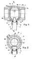
- Fig. 1 is a sectional view of a ball valve according to the invention.
- Fig. 2 is a view of the ball valve shown in FIG. 1, cut along a plane containing the axis of rotation of the plug.
- the isolation tap with three orifices 9a, 9b, 9c comprises a plug 6 which can rotate around an axis corresponding to the intersection of the planes A-A and B-B and an operating rod 2 of the plug 6.
- Said valve comprises a body 1, a nipple 3, two seals, one 5a upstream and the other 5b downstream of the valve 6. Said valve 6 is clamped between the two seals by screwing the nipple 3 in the body 1.
- the valve also includes a gasket 4 trapped between the two seals, the nipple 3, the body 1 and the plug 6.
- the valve includes a rod nut 7 and an O-ring 8.
- the operating rod 2 is of partially cylindrical shape. From the contact end with the plug 6 towards the operating end, the rod 2 has a finger 14 of substantially rectangular shape, milled at its end. The two other faces remaining at a thickness close to the diameter of the rod 2. Then the rod 2 has a cylindrical end 12. Approaching the operating end, the rod 2 has a groove, after the cylindrical surface along the groove, the diameter of the rod 2 is reduced so as to form a shoulder.
- Said operating rod 2 of the plug 6 is held by means of the nut 7 in the form of a threaded ring on its external face and bored to the diameter of the operating rod 2 on its internal face.
- the valve plug 6 of the invention is spherical.
- Said plug 6 is pierced with a channel 9 transverse to plane B-B.
- the plug 6 comprises a second channel capable of opening at one end into the orifice 9b and opening at the other end through said channel 9 transverse to the plane B-B.
- the second channel is drilled at an angle of 45% relative to the plane B-B and perpendicular to the first hole.
- Said plug 6 further having a groove 13 intended to receive the finger 14 at the end of the operating rod 2.
- the external surface 10 of the plug 6, remaining free is coated by the lining 4.
- the lining 4 has an internal face 11 of spherical shape cut along two planes parallel to the plane B-B and centered with respect to said plane B-B.
- the lining 4 has two holes, the first centered with respect to the plane BB and of the same diameter as the cylindrical end 12 of the rod 2, the second is located at an equal distance from each of the two planes parallel to the BB axis and its axis being 135 ° from the first drilling.
- the lining 4 is deformable.
- the linings 5a and 5b are in the form of a ring whose outside diameter is identical and constant and the inside diameter is frustoconical.
- the nipple 3 is substantially in the shape of a hollow cylinder whose external cylindrical surface is threaded at one end and smooth at the other end and has two shoulders, each facing one end.
- the internal cylindrical surface of the nipple 3 is tapped at one end and smooth at the other end and has two shoulders, each facing one end.
- the thread opens at the other end than the thread.
- the body 1 is of the general shape of a rectangular parallelepiped comprising a cylindrical projection and holes along three axes.
- One of the holes is made along the axis of intersection of the planes A-A and B-B and opens perpendicularly into the hole coaxial with the cylindrical projection.
- the axis of the third hole is 45 ° from the plane A-A and in the plane B-B and opens perpendicularly into the hole coaxial with the cylindrical projection.
- Said bore coaxial with the cylindrical projection has its axis contained in the plane A-A and perpendicular to the plane B-B.
- the cylindrical projection is threaded.
- the bore whose axis is included in the plane A-A is tapped at one end, then has two successive shoulders and emerges from the cylindrical projection.
- the other two holes are tapped towards the outside of the body 1.
- the lining 5b is mounted at the bottom of the second shoulder of the bore of the body 1, the axis of which is included in the plane A-A.
- the lining 4 coats the plug 6.
- the part projecting beyond the coating with the lining 4 of the plug 6 is housed in contact with the internal surface of the lining 5b.
- the lining 4 resting on the lining 5b and the first shoulder of the bore of the body 1, the axis of which is included in the plane AA.
- the lining 5a is mounted in the smooth internal cylindrical part of the nipple 3. The screwing of the nipple 3 in the tapping of the bore, the axis of which is included in the plane AA, of the body 1 comes to tighten and maintain in their housing the plug 6 and the trim 4.
- the finger 14 of the rod 2 cooperates with the groove 13 of the plug 6.
- the gasket 4 surrounds the entire circumference of the cylindrical end 12 of the operating rod 2.
- the O-ring 8 is housed in the groove of the rod 2. This is held by the nut 7 screwed into the body 1 and in abutment on the shoulder of the rod 2.
- the fluid enters through the upstream orifice 9a and flows through the orifices 9b and 9c.
- a quarter-turn rotation of the rod 2 causes a quarter-turn rotation of the plug 6, which isolates all the orifices from one another.
- the tap is closed.
- the fluid By extending said rotation by a second quarter of a turn, the fluid enters through the upstream orifice 9a and flows only through the orifice 9c.
- Port 9b is insulated.
- the valve according to the invention can be connected to pipes carrying a fluid at different temperatures.
Landscapes
- Engineering & Computer Science (AREA)
- General Engineering & Computer Science (AREA)
- Mechanical Engineering (AREA)
- Taps Or Cocks (AREA)
- Valve Housings (AREA)
Applications Claiming Priority (2)
| Application Number | Priority Date | Filing Date | Title |
|---|---|---|---|
| FR9104219 | 1991-04-03 | ||
| FR9104219A FR2674931B1 (fr) | 1991-04-03 | 1991-04-03 | Moyen d'isolement pour canaliser un fluide comprenant trois orifices dont deux voies. |
Publications (2)
| Publication Number | Publication Date |
|---|---|
| EP0507716A1 true EP0507716A1 (de) | 1992-10-07 |
| EP0507716B1 EP0507716B1 (de) | 1996-03-06 |
Family
ID=9411560
Family Applications (1)
| Application Number | Title | Priority Date | Filing Date |
|---|---|---|---|
| EP19920470013 Expired - Lifetime EP0507716B1 (de) | 1991-04-03 | 1992-03-25 | Vorrichtung zur Isolierung und Verbindung von mehreren Fliesswegen für Flüssigkeiten und Hahn mit einer derartigen Vorrichtung |
Country Status (4)
| Country | Link |
|---|---|
| EP (1) | EP0507716B1 (de) |
| DE (1) | DE69208707D1 (de) |
| ES (1) | ES2084321T3 (de) |
| FR (1) | FR2674931B1 (de) |
Cited By (1)
| Publication number | Priority date | Publication date | Assignee | Title |
|---|---|---|---|---|
| US6540206B2 (en) * | 2000-05-24 | 2003-04-01 | Fratelli Guerra Kmp Srl | Bidirectional ball valve particularly for ecological frigorific gases |
Citations (4)
| Publication number | Priority date | Publication date | Assignee | Title |
|---|---|---|---|---|
| US3209779A (en) * | 1962-06-11 | 1965-10-05 | Camco Inc | Orifice valve assembly |
| US3674052A (en) * | 1970-01-12 | 1972-07-04 | Stile Craft Mfg Inc | Ball valve |
| EP0055066A1 (de) * | 1980-12-24 | 1982-06-30 | Smith Valve Corporation | Überwachungsventil eines Flüssigkeitsstroms |
| EP0417706A2 (de) * | 1989-09-12 | 1991-03-20 | CHEMAT GmbH Armaturen für Industrie- und Nuklearanlagen | Absperrhahn |
-
1991
- 1991-04-03 FR FR9104219A patent/FR2674931B1/fr not_active Expired - Fee Related
-
1992
- 1992-03-25 DE DE69208707T patent/DE69208707D1/de not_active Expired - Lifetime
- 1992-03-25 ES ES92470013T patent/ES2084321T3/es not_active Expired - Lifetime
- 1992-03-25 EP EP19920470013 patent/EP0507716B1/de not_active Expired - Lifetime
Patent Citations (4)
| Publication number | Priority date | Publication date | Assignee | Title |
|---|---|---|---|---|
| US3209779A (en) * | 1962-06-11 | 1965-10-05 | Camco Inc | Orifice valve assembly |
| US3674052A (en) * | 1970-01-12 | 1972-07-04 | Stile Craft Mfg Inc | Ball valve |
| EP0055066A1 (de) * | 1980-12-24 | 1982-06-30 | Smith Valve Corporation | Überwachungsventil eines Flüssigkeitsstroms |
| EP0417706A2 (de) * | 1989-09-12 | 1991-03-20 | CHEMAT GmbH Armaturen für Industrie- und Nuklearanlagen | Absperrhahn |
Cited By (1)
| Publication number | Priority date | Publication date | Assignee | Title |
|---|---|---|---|---|
| US6540206B2 (en) * | 2000-05-24 | 2003-04-01 | Fratelli Guerra Kmp Srl | Bidirectional ball valve particularly for ecological frigorific gases |
Also Published As
| Publication number | Publication date |
|---|---|
| EP0507716B1 (de) | 1996-03-06 |
| FR2674931A1 (fr) | 1992-10-09 |
| ES2084321T3 (es) | 1996-05-01 |
| DE69208707D1 (de) | 1996-04-11 |
| FR2674931B1 (fr) | 1993-07-02 |
Similar Documents
| Publication | Publication Date | Title |
|---|---|---|
| FR2655571A1 (fr) | Dispositif support de buses, a changement rapide. | |
| EP1351776B1 (de) | Ventil-modul für farbvorrichtung | |
| WO2002057672A1 (fr) | Vanne a pointeau a commande pneumatique | |
| EP0328472B1 (de) | Anlasser-Verbindungsstück für die stufenlose Druckzufuhr in pneumatischen Anlagen | |
| FR2727734A1 (fr) | Vannes de reglage a double debit | |
| EP0507716B1 (de) | Vorrichtung zur Isolierung und Verbindung von mehreren Fliesswegen für Flüssigkeiten und Hahn mit einer derartigen Vorrichtung | |
| FR2553489A1 (fr) | Robinet d'arret pour liquides | |
| EP0041007B1 (de) | Druckrelais zur Positionsangabe des beweglichen Teils eines Arbeitzylinders | |
| FR2660726A1 (fr) | Raccord - distributeur pour la commande d'actionneurs pneumatiques. | |
| FR3059074B1 (fr) | Dispositif de connexion fluidique | |
| EP0635310A1 (de) | Betätigungspistole für Düsen | |
| EP0350394B1 (de) | Regenwasserabflussanordnung | |
| FR2552842A1 (fr) | Robinet d'arret a boule avec canal d'ecoulement a profil modifiable | |
| LU86439A1 (fr) | Robinet pour gaz comprimes ou liquefies | |
| FR2607570A1 (fr) | Robinet soude a double etancheite | |
| FR2848281A1 (fr) | Robinet a boisseau | |
| EP1600674A1 (de) | Ventil für Gasbehälter | |
| FR2657429A1 (fr) | Dispositif de mesure pneumatique. | |
| EP0098621B1 (de) | Mischventil für Warm- und Kaltwasser | |
| FR2467339A1 (fr) | Robinet a ecrou plombable, notamment pour les compteurs d'eau et de gaz | |
| FR2820488A1 (fr) | Robinet trois voies a sphere perfectionnee pour dispositif de prise en charge et procede de montage | |
| FR2664016A1 (fr) | Robinet a boisseau. | |
| EP0356364A1 (de) | Speziell für Plastikrohre geeignete Verbindung | |
| FR2571817A1 (fr) | Raccord rapide perfectionne pour canalisations de fluide sous pression, et application d'un tel raccord au gonflage d'un reservoir | |
| FR2506891A1 (fr) | Raccord tournant a obturation pour alimentation en fluide d'un appareil tournant |
Legal Events
| Date | Code | Title | Description |
|---|---|---|---|
| PUAI | Public reference made under article 153(3) epc to a published international application that has entered the european phase |
Free format text: ORIGINAL CODE: 0009012 |
|
| AK | Designated contracting states |
Kind code of ref document: A1 Designated state(s): BE DE ES FR GB IT NL |
|
| 17P | Request for examination filed |
Effective date: 19921210 |
|
| 17Q | First examination report despatched |
Effective date: 19940526 |
|
| GRAH | Despatch of communication of intention to grant a patent |
Free format text: ORIGINAL CODE: EPIDOS IGRA |
|
| GRAA | (expected) grant |
Free format text: ORIGINAL CODE: 0009210 |
|
| AK | Designated contracting states |
Kind code of ref document: B1 Designated state(s): BE DE ES FR GB IT NL |
|
| PG25 | Lapsed in a contracting state [announced via postgrant information from national office to epo] |
Ref country code: NL Free format text: LAPSE BECAUSE OF FAILURE TO SUBMIT A TRANSLATION OF THE DESCRIPTION OR TO PAY THE FEE WITHIN THE PRESCRIBED TIME-LIMIT Effective date: 19960306 Ref country code: GB Effective date: 19960306 |
|
| ITF | It: translation for a ep patent filed | ||
| REF | Corresponds to: |
Ref document number: 69208707 Country of ref document: DE Date of ref document: 19960411 |
|
| REG | Reference to a national code |
Ref country code: ES Ref legal event code: FG2A Ref document number: 2084321 Country of ref document: ES Kind code of ref document: T3 |
|
| PG25 | Lapsed in a contracting state [announced via postgrant information from national office to epo] |
Ref country code: DE Effective date: 19960608 |
|
| NLV1 | Nl: lapsed or annulled due to failure to fulfill the requirements of art. 29p and 29m of the patents act | ||
| GBV | Gb: ep patent (uk) treated as always having been void in accordance with gb section 77(7)/1977 [no translation filed] |
Effective date: 19960306 |
|
| PLBE | No opposition filed within time limit |
Free format text: ORIGINAL CODE: 0009261 |
|
| 26N | No opposition filed | ||
| PGFP | Annual fee paid to national office [announced via postgrant information from national office to epo] |
Ref country code: BE Payment date: 20010124 Year of fee payment: 10 |
|
| PGFP | Annual fee paid to national office [announced via postgrant information from national office to epo] |
Ref country code: ES Payment date: 20010313 Year of fee payment: 10 |
|
| PG25 | Lapsed in a contracting state [announced via postgrant information from national office to epo] |
Ref country code: ES Free format text: LAPSE BECAUSE OF NON-PAYMENT OF DUE FEES Effective date: 20020326 |
|
| PG25 | Lapsed in a contracting state [announced via postgrant information from national office to epo] |
Ref country code: BE Free format text: LAPSE BECAUSE OF NON-PAYMENT OF DUE FEES Effective date: 20020331 |
|
| BERE | Be: lapsed |
Owner name: *COMAP Effective date: 20020331 |
|
| PGFP | Annual fee paid to national office [announced via postgrant information from national office to epo] |
Ref country code: FR Payment date: 20040116 Year of fee payment: 13 |
|
| REG | Reference to a national code |
Ref country code: ES Ref legal event code: FD2A Effective date: 20030410 |
|
| PG25 | Lapsed in a contracting state [announced via postgrant information from national office to epo] |
Ref country code: IT Free format text: LAPSE BECAUSE OF NON-PAYMENT OF DUE FEES;WARNING: LAPSES OF ITALIAN PATENTS WITH EFFECTIVE DATE BEFORE 2007 MAY HAVE OCCURRED AT ANY TIME BEFORE 2007. THE CORRECT EFFECTIVE DATE MAY BE DIFFERENT FROM THE ONE RECORDED. Effective date: 20050325 |
|
| PG25 | Lapsed in a contracting state [announced via postgrant information from national office to epo] |
Ref country code: FR Free format text: LAPSE BECAUSE OF NON-PAYMENT OF DUE FEES Effective date: 20051130 |
|
| REG | Reference to a national code |
Ref country code: FR Ref legal event code: ST Effective date: 20051130 |