EP0507741A2 - Machine d'usinage à décharge électrique et découpage par fil - Google Patents
Machine d'usinage à décharge électrique et découpage par fil Download PDFInfo
- Publication number
- EP0507741A2 EP0507741A2 EP92810241A EP92810241A EP0507741A2 EP 0507741 A2 EP0507741 A2 EP 0507741A2 EP 92810241 A EP92810241 A EP 92810241A EP 92810241 A EP92810241 A EP 92810241A EP 0507741 A2 EP0507741 A2 EP 0507741A2
- Authority
- EP
- European Patent Office
- Prior art keywords
- axis
- workpiece
- column
- wire
- moving block
- Prior art date
- Legal status (The legal status is an assumption and is not a legal conclusion. Google has not performed a legal analysis and makes no representation as to the accuracy of the status listed.)
- Granted
Links
Images


Classifications
-
- B—PERFORMING OPERATIONS; TRANSPORTING
- B23—MACHINE TOOLS; METAL-WORKING NOT OTHERWISE PROVIDED FOR
- B23H—WORKING OF METAL BY THE ACTION OF A HIGH CONCENTRATION OF ELECTRIC CURRENT ON A WORKPIECE USING AN ELECTRODE WHICH TAKES THE PLACE OF A TOOL; SUCH WORKING COMBINED WITH OTHER FORMS OF WORKING OF METAL
- B23H7/00—Processes or apparatus applicable to both electrical discharge machining and electrochemical machining
- B23H7/02—Wire-cutting
Definitions
- the invention generally relates to electroerosion machines and, more particularly, to wire-cut electric discharge machines which are capable of independent motion in the X and Y axes.
- wire-cut electric discharge machines In general, electrical discharges between a workpiece and an electrode remove pieces of the workpiece, thereby resulting in the cutting of the workpiece.
- a generally vertically extending wire is used as the electrode and as it moves relative to the workpiece, a contour is cut in the workpiece.
- the operation of machining using wire-cut electroerosion machine may be analogized with the cutting that occurs using a blade in a jigsaw or bandsaw as it cuts a contour in a workpiece.
- a conventional EDM machine such as the one depicted in Fig. 1, has a double deck construction comprising a saddle 4 and a table 6.
- the saddle 4 moves relative to the fixed bed 2 in the X-axis and the table 6 moves relative to the saddle 4 in the Y-axis.
- a machining tank 8 is located on the table 6 and holds a machining fluid.
- a workpiece 12 is mounted within the machining tank 8 by a mounting table 10.
- a wire electrode feeding mechanism 16 is located on a side of a fixed column 14 for dispensing a wire electrode 18 through an upper guide 20, the workpiece 12, a lower guide 22, to a lower arm 24.
- the upper guide 20 can move not only in the vertical direction, which is the Z-axis, but also in a U-axis and in a V-axis for performing taper cuts.
- the lower arm 24 is fixed to the column 14 and to a slide plate. The slide plate enables the machining tank 8 to move in the X-axis relative to the lower arm 24 and provides a liquid tight seal between the lower arm 24 and the machining tank 8.
- the lower arm may instead be L-shaped and extend down from the fixed column 14 into the machining tank 8 without passing through a side of the tank 8.
- the double deck arrangement of the saddle 4 and table 6 is suitable only for small light workpieces. As the workpieces become larger and heavier, the machining tank 8 must expand to accommodate the workpieces. Consequently, the saddle 4 and the table 6 must also be enlarged to maintain a full range of motion within the X-Y plane and must be enlarged so that they can support the heavier load.
- the machining area is preferably about 1 meter high to enable easy access by an operator.
- the double deck construction must increase in height in order to be able to withstand the heavier load.
- a platform is needed to allow the operator to access the machining area or some portions of the machine would have to be embedded. In either event, access to the machining area is hindered.
- FIG. 2 Another example of a conventional EDM machine is illustrated in Fig. 2.
- the EDM machine depicted in Fig. 2 comprises a table 32 that moves a machining tank 34 along a Y-axis over a pair of rails that are affixed to a fixed bed 30.
- An upper guide 40 and a lower guide 42 are attached to a moving block 38 through an upper arm and lower arm, respectively.
- the moving block 38 moves along an X-axis on a pair of guide rails that are affixed to a vertical surface of a column 36.
- the motion in the X-axis is independent of the motion in the Y-axis.
- the EDM machine of Fig. 2 still inhibits access to the workpiece when it is moved to its further position in the Y-axis. Also, both ends of the machining tank 34 are blocked by the column 36 to further hinder access to the workpiece. Additionally, an automatic pallet changer for automatically changing the workpieces would be difficult to use with the embodiment of Fig. 2. Further, since the moving block 38 was mounted on its side to the column 36, sub-micron accuracy in the machining is difficult to attain.
- an electroerosion machine comprises a table for moving a workpiece along an X-axis and a Y-axis transfer mechanism for moving an upper guide and a lower guide along the Y-axis.
- the Y-axis transfer mechanism moves on a horizontal planar surface of the column.
- a wire feed mechanism feeds a wire electrode through the upper guide, workpiece, and then to the lower guide.
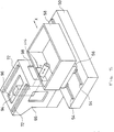
- An exemplary wire-cut EDM machine includes of a fixed bed 50 upon which a pair of rails 54 are affixed for guiding a table 56 along an X-axis.
- a machining tank 58 preferably having a rectangular shape and an open top end, is attached to the table 56 and has a mounting fixture 62 for holding a workpiece 60.
- a side wall of the machining tank 58 may be used as a door 64 for accessing the workpiece 60.
- a fixed column 66 extends to a height above the machining tank 58 and preferably has a hollow construction as shown in Fig. 5.
- Y-axis transfer mechanism 68 travels along a guide, for example, a pair of rails 72 on top of a horizontal plane of the column 66 as depicted in Fig. 5.
- the Y-axis transfer mechanism also includes a moving block 70 which preferably comprises, for example, linear bearings and a servo motor for moving the transfer mechanism along the Y-axis.
- a wire bobbin 74 located at the forward end of the moving block 70, which also includes a plurality of rollers through which a wire electrode 73 is unwound.
- a wire feed device 76 also preferably positioned at the forward end of the moving block 70, dispenses the wire electrode to a block 78 which is movable in the Z-axis direction and down through an upper arm 80.
- the block 78 moves the upper arm 80 and an upper wire guide 82 up and down along the Z-axis.
- a block 90 (Fig.
- movable in the U-V plane is located between the upper arm 80 and the moving block 78 and moves the upper arm 80 and upper wire guide 82 in the U-V plane, which is parallel to the X-Y plane, in order to perform taper cuts.
- An automatic wire threading mechanism 84 may be provided for automatically threading the wire electrode 73.
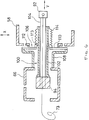
- a lower wire guide 92 receives the wire electrode 73 after it passes through the workpiece 60. From the lower wire guide 92, the wire electrode 73 passes through an L-shaped lower arm 94 (best seen in Fig. 5), which has its upper end integral with the moving block 70 (see Fig. 3). The lower arm 94 passes through an opening 96 in the column 66 before reaching the moving block 70. The lower arm 94 also passes through a second opening 98 in the column 66 and through an opening 106 in a side wall of the machining tank 58 (see Fig. 6). The lower arm 94 and the moving block 70 move along the Y-axis as a single assembly.
- section 100 of the lower arm 94 extends from inside the column 66 to the inside of the machining tank 58.
- the section 100 preferably comprises a hollow outer cylinder 102 with an inner cylinder 104 inserted therein.
- the inner cylinder 104 extends slightly further inside the machining tank 58 than the outer cylinder 102.
- the lower wire guide 92 is positioned at the end of the inner cylinder 104 for receiving the wire electrode 73 from the upper wire guide 82. The wire then travels through the inner cylinder 104 to a take-up mechanism positioned downstream.
- the opening 106 on the side wall of the machining tank 58 is wider than the maximum amount of motion along the X-axis so as to not cause any interference with the lower arm 94.
- a slide plate 110 preferably formed of stainless steel, is attached to the fixed column 66 through a support 108.
- the slide plate 110 is also slidable relative to the machining tank 58 through a liquid-tight seal 112.
- the seal 112 and slide plate 110 enable the lower arm 94 to move along the X-axis in a sealed relationship with the machining tank 58.
- Bellows 114 extend from the tip of the outer cylinder 102 to the slide plate 110 to provide a liquid-tight seal therebetween.
- the bellows 114 seal an opening 113 between the outer cylinder 102 and the slide plate 110 and allow the lower arm unit to move along the Y-axis while preventing the machining fluid from draining out of the machining tank 58.
- the wire electrode 73 is dispensed from the wire electrode feeder 76 through the automatic wire threader to the upper guide 82, through the workpiece 60, lower guide 92, down through the inner cylinder 104 of the lower arm 94, and then discharged outside of the machine.
- the table 56 To perform cuts along the X-axis, the table 56, having the machining tank 58 with the workpiece 60 mounted inside, is moved on a pair of rails 54 along the X-axis.
- the slide plate 110 and seal 112 enable movement along the X-axis in a sealed arrangement with the machining tank 58.
- the moving block 70 To perform cuts along the Y-axis, the moving block 70 is movable along a pair of rails 72 which run parallel to the Y-axis.
- the upper arm 80, together with the upper wire guide 82, and the lower arm 94, together with the lower wire guide 92, move as a unit along the Y-axis together with the moving block 70.
- the contraction and expansion of the bellows 114 enable the lower arm 94 to move along the Y-axis in a sealed arrangement with the machining tank 58.
- the distance between the upper wire guide 82 and the lower wire guide 92 is adjustable by means of the moving block 78, which moves the upper wire guide 82 up or down in the Z-axis.
- the moving block 90 By moving the upper wire guide 82 in the U-V plane without moving the lower wire guide 92, the moving block 90 enables the EDM machine to perform taper/ cuts.
- machining will be accomplished by combinations of all types of motions.
- the machining tank 58 moves only along the X-axis and the wire electrode 71 is independently moved along the Y-axis. Together these movements define relative movement between the wire electrode and workpiece in the X-Y plane.
- the single deck construction of the invention reduces the need to expand the machine's size with larger and heavier workpieces.
- the single deck construction also reduces the height of the machine and therefore reduces the need for a platform or for any embedding of the machine. Even when the workpiece is moved to its furthest position along the Y-axis, the operator may still easily access the workpiece.
- the invention uses a moving block 70 which moves along a pair of rails 72 and which are placed on a horizontal plane of the column 66. This is in contrast to the conventional design of Fig. 2 which places the rails onto a vertical surface of the column. By placing the rails on a horizontal surface, rattling of the moving block 70 is eliminated and the machining accuracy is improved. Also, since the column 66 is positioned generally behind the machining tank 58 and since the upper and lower guides, 82 and 92, respectively, are disposed within the column, both sides of the machining tank 58 are easily accessible and available, for example, for use with an automatic pallet changer.
- the lower arm may be L-shaped and need not pass through a side wall of the machining tank 58.
- a linear guide may be located between the upper and lower stages of the column for providing motion along the X-axis.
Landscapes
- Chemical & Material Sciences (AREA)
- Chemical Kinetics & Catalysis (AREA)
- Electrochemistry (AREA)
- Engineering & Computer Science (AREA)
- Mechanical Engineering (AREA)
- Electrical Discharge Machining, Electrochemical Machining, And Combined Machining (AREA)
Applications Claiming Priority (2)
| Application Number | Priority Date | Filing Date | Title |
|---|---|---|---|
| JP96227/91 | 1991-04-02 | ||
| JP3096227A JP2970883B2 (ja) | 1991-04-02 | 1991-04-02 | ワイヤ放電加工機 |
Publications (3)
| Publication Number | Publication Date |
|---|---|
| EP0507741A2 true EP0507741A2 (fr) | 1992-10-07 |
| EP0507741A3 EP0507741A3 (en) | 1993-01-27 |
| EP0507741B1 EP0507741B1 (fr) | 1994-12-14 |
Family
ID=14159349
Family Applications (1)
| Application Number | Title | Priority Date | Filing Date |
|---|---|---|---|
| EP92810241A Expired - Lifetime EP0507741B1 (fr) | 1991-04-02 | 1992-04-01 | Machine d'usinage à décharge électrique et découpage par fil |
Country Status (5)
| Country | Link |
|---|---|
| US (1) | US5243165A (fr) |
| EP (1) | EP0507741B1 (fr) |
| JP (1) | JP2970883B2 (fr) |
| DE (1) | DE69200879T2 (fr) |
| HK (1) | HK82995A (fr) |
Cited By (2)
| Publication number | Priority date | Publication date | Assignee | Title |
|---|---|---|---|---|
| US6486429B1 (en) | 1999-07-13 | 2002-11-26 | Agie Sa | Electric discharge machine and module set for assembly of machine tools |
| CN107081493A (zh) * | 2017-07-03 | 2017-08-22 | 董靖 | 一种线切割支架 |
Families Citing this family (9)
| Publication number | Priority date | Publication date | Assignee | Title |
|---|---|---|---|---|
| EP0781619A1 (fr) | 1995-12-15 | 1997-07-02 | Cree Research, Inc. | Procédé de fabrication des plaquettes en carbure de silicium à partir des monocristaux en carbure de silicium |
| DE19640790C2 (de) * | 1996-10-02 | 2001-04-26 | Agie Sa | Verfahren und Vorrichtung zum funkenerosiven Bearbeiten |
| WO1999000212A1 (fr) * | 1997-06-26 | 1999-01-07 | Mitsubishi Denki Kabushiki Kaisha | Decharge electrique par cable |
| JP4004666B2 (ja) * | 1998-10-12 | 2007-11-07 | 株式会社ソディック | ワイヤカット放電加工機 |
| US6627835B1 (en) | 2000-02-02 | 2003-09-30 | Purdue Research Foundation | Three dimensional object fabrication techniques |
| ATE517705T1 (de) * | 2007-06-30 | 2011-08-15 | Trumpf Werkzeugmaschinen Gmbh | Werkzeugmaschine und verfahren zum ausschleusen eines werkstückteils |
| US7973260B2 (en) * | 2008-02-01 | 2011-07-05 | Industrial Technology Research Institute | Wire electrical discharge machining |
| DE112012007087B4 (de) * | 2012-10-30 | 2022-10-20 | Mitsubishi Electric Corporation | Elektrische Drahtentladungsbearbeitungsvorrichtung |
| JP5731613B2 (ja) * | 2013-10-18 | 2015-06-10 | ファナック株式会社 | ワイヤ放電加工機およびワイヤ放電加工機の制御装置 |
Family Cites Families (9)
| Publication number | Priority date | Publication date | Assignee | Title |
|---|---|---|---|---|
| US3731044A (en) * | 1971-06-23 | 1973-05-01 | Agie Ag Ind Elektronik | Electro-eroding machine with a circuit for the control of at least one advancing device for a wire electrode and/or for a workpiece |
| US3731045A (en) * | 1971-07-01 | 1973-05-01 | Agie Ag Ind Elektronik | Circuit for an electro-eroding machine for the control of the relative movement between at least one electrode and at least one workpiece |
| CH632693A5 (fr) * | 1979-12-21 | 1982-10-29 | Charmilles Sa Ateliers | Machine pour decouper par etincelage erosif. |
| DE3524377A1 (de) * | 1985-07-08 | 1987-01-15 | Agie Ag Ind Elektronik | Elektroerosions-schneidmaschine in c-gestell-bauweise |
| DE3632347A1 (de) * | 1986-09-24 | 1988-03-31 | Schiess Ag Geschaeftsbereich S | Werkzeugmaschine, insbesondere funkenerosionsmaschine |
| DE3738251C2 (de) * | 1986-11-17 | 1994-09-22 | Inst Tech Precision Eng | Funkenerosive Drahtschneidemaschine |
| JP2637473B2 (ja) * | 1988-06-03 | 1997-08-06 | 日立精工株式会社 | ワイヤ放電加工機 |
| JPH02139127A (ja) * | 1988-11-15 | 1990-05-29 | Mitsubishi Electric Corp | ワイヤ放電加工装置 |
| DE3841314A1 (de) * | 1988-12-08 | 1990-06-13 | Schiess Ag Geschaeftsbereich S | Drahterodiermaschine |
-
1991
- 1991-04-02 JP JP3096227A patent/JP2970883B2/ja not_active Expired - Fee Related
-
1992
- 1992-03-30 US US07/859,864 patent/US5243165A/en not_active Expired - Lifetime
- 1992-04-01 EP EP92810241A patent/EP0507741B1/fr not_active Expired - Lifetime
- 1992-04-01 DE DE69200879T patent/DE69200879T2/de not_active Expired - Fee Related
-
1995
- 1995-05-25 HK HK82995A patent/HK82995A/en not_active IP Right Cessation
Cited By (3)
| Publication number | Priority date | Publication date | Assignee | Title |
|---|---|---|---|---|
| US6486429B1 (en) | 1999-07-13 | 2002-11-26 | Agie Sa | Electric discharge machine and module set for assembly of machine tools |
| EP1068922A3 (fr) * | 1999-07-13 | 2003-05-21 | Agie Sa | Machine pour usinage par électroérosion, un set de modules pour construire des machines-outils, en particulier des machines pour usinage par électroérosion |
| CN107081493A (zh) * | 2017-07-03 | 2017-08-22 | 董靖 | 一种线切割支架 |
Also Published As
| Publication number | Publication date |
|---|---|
| JP2970883B2 (ja) | 1999-11-02 |
| HK82995A (en) | 1995-06-01 |
| EP0507741B1 (fr) | 1994-12-14 |
| JPH04304927A (ja) | 1992-10-28 |
| DE69200879T2 (de) | 1995-04-20 |
| US5243165A (en) | 1993-09-07 |
| EP0507741A3 (en) | 1993-01-27 |
| DE69200879D1 (de) | 1995-01-26 |
Similar Documents
| Publication | Publication Date | Title |
|---|---|---|
| EP0507741B1 (fr) | Machine d'usinage à décharge électrique et découpage par fil | |
| US6486429B1 (en) | Electric discharge machine and module set for assembly of machine tools | |
| US5086203A (en) | Wire electric discharge machining apparatus | |
| US6246024B1 (en) | Wire electric discharge machining apparatus | |
| JP2002205231A (ja) | 工作機械、特に切削放電加工機ならびにモジュール・セット | |
| EP0610974B1 (fr) | Appareil de découpe par fil, par électro-érosion | |
| EP0229186B1 (fr) | Machine d'usinage par etincelage a fil de coupe | |
| US4227064A (en) | Device for advancing a workpiece in electro-erosive processing by a wire-like electrode | |
| EP1413388A1 (fr) | Machine-outil à glissières hydrostatiques à pression variable | |
| US6201205B1 (en) | Wire-cut electric discharge machine | |
| JP3161687B2 (ja) | 電極ガイド自動交換装置を備えた放電加工機 | |
| JPH08118155A (ja) | 浸漬型ワイヤカット放電加工機 | |
| JPH0466647B2 (fr) | ||
| KR970002544B1 (ko) | 수평식 와이어 방전가공기 | |
| JP3669826B2 (ja) | 浸漬式ワイヤ放電加工機 | |
| EP0203035B1 (fr) | Système pour le guidage d'une colonne d'une machine-outil améliorant la précision de la machine | |
| EP4238679A1 (fr) | Machine-outil | |
| US5026961A (en) | Feed apparatus | |
| RU131325U1 (ru) | Станок электроэрозионный вырезной малогабаритный | |
| JPH06134622A (ja) | ワイヤ放電加工機 | |
| JP2000052150A (ja) | ワイヤ放電加工装置及びワイヤ放電加工方法 | |
| KR940006700A (ko) | 와이어 컷 방전가공기 | |
| JPH052252Y2 (fr) | ||
| JPS62264824A (ja) | ワイヤカツト放電加工機のテ−パ加工装置 | |
| JPS61226224A (ja) | 往復二線式ワイヤカツト放電加工装置 |
Legal Events
| Date | Code | Title | Description |
|---|---|---|---|
| PUAI | Public reference made under article 153(3) epc to a published international application that has entered the european phase |
Free format text: ORIGINAL CODE: 0009012 |
|
| AK | Designated contracting states |
Kind code of ref document: A2 Designated state(s): CH DE FR GB IT LI |
|
| PUAL | Search report despatched |
Free format text: ORIGINAL CODE: 0009013 |
|
| AK | Designated contracting states |
Kind code of ref document: A3 Designated state(s): CH DE FR GB IT LI |
|
| 17P | Request for examination filed |
Effective date: 19930706 |
|
| 17Q | First examination report despatched |
Effective date: 19940509 |
|
| GRAA | (expected) grant |
Free format text: ORIGINAL CODE: 0009210 |
|
| AK | Designated contracting states |
Kind code of ref document: B1 Designated state(s): CH DE FR GB IT LI |
|
| ITF | It: translation for a ep patent filed | ||
| REF | Corresponds to: |
Ref document number: 69200879 Country of ref document: DE Date of ref document: 19950126 |
|
| ET | Fr: translation filed | ||
| PLBE | No opposition filed within time limit |
Free format text: ORIGINAL CODE: 0009261 |
|
| 26N | No opposition filed | ||
| REG | Reference to a national code |
Ref country code: GB Ref legal event code: IF02 |
|
| PGFP | Annual fee paid to national office [announced via postgrant information from national office to epo] |
Ref country code: FR Payment date: 20080312 Year of fee payment: 17 Ref country code: DE Payment date: 20080411 Year of fee payment: 17 |
|
| PGFP | Annual fee paid to national office [announced via postgrant information from national office to epo] |
Ref country code: IT Payment date: 20080428 Year of fee payment: 17 |
|
| REG | Reference to a national code |
Ref country code: CH Ref legal event code: PCAR Free format text: AMMANN PATENTANWAELTE AG BERN;SCHWARZTORSTRASSE 31;3001 BERN (CH) |
|
| REG | Reference to a national code |
Ref country code: FR Ref legal event code: ST Effective date: 20091231 |
|
| PG25 | Lapsed in a contracting state [announced via postgrant information from national office to epo] |
Ref country code: DE Free format text: LAPSE BECAUSE OF NON-PAYMENT OF DUE FEES Effective date: 20091103 |
|
| PG25 | Lapsed in a contracting state [announced via postgrant information from national office to epo] |
Ref country code: FR Free format text: LAPSE BECAUSE OF NON-PAYMENT OF DUE FEES Effective date: 20091222 |
|
| PGFP | Annual fee paid to national office [announced via postgrant information from national office to epo] |
Ref country code: GB Payment date: 20100325 Year of fee payment: 19 |
|
| PGFP | Annual fee paid to national office [announced via postgrant information from national office to epo] |
Ref country code: CH Payment date: 20100414 Year of fee payment: 19 |
|
| PG25 | Lapsed in a contracting state [announced via postgrant information from national office to epo] |
Ref country code: IT Free format text: LAPSE BECAUSE OF NON-PAYMENT OF DUE FEES Effective date: 20090401 |
|
| REG | Reference to a national code |
Ref country code: CH Ref legal event code: PL |
|
| GBPC | Gb: european patent ceased through non-payment of renewal fee |
Effective date: 20110401 |
|
| PG25 | Lapsed in a contracting state [announced via postgrant information from national office to epo] |
Ref country code: CH Free format text: LAPSE BECAUSE OF NON-PAYMENT OF DUE FEES Effective date: 20110430 Ref country code: LI Free format text: LAPSE BECAUSE OF NON-PAYMENT OF DUE FEES Effective date: 20110430 |
|
| PG25 | Lapsed in a contracting state [announced via postgrant information from national office to epo] |
Ref country code: GB Free format text: LAPSE BECAUSE OF NON-PAYMENT OF DUE FEES Effective date: 20110401 |