EP0508017A1 - Flachdichtung aus Metalllaminat mit einer Graphitschicht - Google Patents
Flachdichtung aus Metalllaminat mit einer Graphitschicht Download PDFInfo
- Publication number
- EP0508017A1 EP0508017A1 EP91309091A EP91309091A EP0508017A1 EP 0508017 A1 EP0508017 A1 EP 0508017A1 EP 91309091 A EP91309091 A EP 91309091A EP 91309091 A EP91309091 A EP 91309091A EP 0508017 A1 EP0508017 A1 EP 0508017A1
- Authority
- EP
- European Patent Office
- Prior art keywords
- plate
- gasket
- hole
- engine
- flange
- Prior art date
- Legal status (The legal status is an assumption and is not a legal conclusion. Google has not performed a legal analysis and makes no representation as to the accuracy of the status listed.)
- Granted
Links
Images
Classifications
-
- F—MECHANICAL ENGINEERING; LIGHTING; HEATING; WEAPONS; BLASTING
- F16—ENGINEERING ELEMENTS AND UNITS; GENERAL MEASURES FOR PRODUCING AND MAINTAINING EFFECTIVE FUNCTIONING OF MACHINES OR INSTALLATIONS; THERMAL INSULATION IN GENERAL
- F16J—PISTONS; CYLINDERS; SEALINGS
- F16J15/00—Sealings
- F16J15/02—Sealings between relatively-stationary surfaces
- F16J15/06—Sealings between relatively-stationary surfaces with solid packing compressed between sealing surfaces
- F16J15/10—Sealings between relatively-stationary surfaces with solid packing compressed between sealing surfaces with non-metallic packing
- F16J15/12—Sealings between relatively-stationary surfaces with solid packing compressed between sealing surfaces with non-metallic packing with metal reinforcement or covering
- F16J15/121—Sealings between relatively-stationary surfaces with solid packing compressed between sealing surfaces with non-metallic packing with metal reinforcement or covering with metal reinforcement
- F16J15/122—Sealings between relatively-stationary surfaces with solid packing compressed between sealing surfaces with non-metallic packing with metal reinforcement or covering with metal reinforcement generally parallel to the surfaces
-
- F—MECHANICAL ENGINEERING; LIGHTING; HEATING; WEAPONS; BLASTING
- F16—ENGINEERING ELEMENTS AND UNITS; GENERAL MEASURES FOR PRODUCING AND MAINTAINING EFFECTIVE FUNCTIONING OF MACHINES OR INSTALLATIONS; THERMAL INSULATION IN GENERAL
- F16J—PISTONS; CYLINDERS; SEALINGS
- F16J15/00—Sealings
- F16J15/02—Sealings between relatively-stationary surfaces
- F16J15/06—Sealings between relatively-stationary surfaces with solid packing compressed between sealing surfaces
- F16J15/08—Sealings between relatively-stationary surfaces with solid packing compressed between sealing surfaces with exclusively metal packing
- F16J15/0818—Flat gaskets
- F16J15/0825—Flat gaskets laminated
-
- F—MECHANICAL ENGINEERING; LIGHTING; HEATING; WEAPONS; BLASTING
- F16—ENGINEERING ELEMENTS AND UNITS; GENERAL MEASURES FOR PRODUCING AND MAINTAINING EFFECTIVE FUNCTIONING OF MACHINES OR INSTALLATIONS; THERMAL INSULATION IN GENERAL
- F16J—PISTONS; CYLINDERS; SEALINGS
- F16J15/00—Sealings
- F16J15/02—Sealings between relatively-stationary surfaces
- F16J15/06—Sealings between relatively-stationary surfaces with solid packing compressed between sealing surfaces
- F16J15/08—Sealings between relatively-stationary surfaces with solid packing compressed between sealing surfaces with exclusively metal packing
- F16J15/0818—Flat gaskets
- F16J2015/0843—Flat gaskets with an edge portion folded over the plate itself
-
- F—MECHANICAL ENGINEERING; LIGHTING; HEATING; WEAPONS; BLASTING
- F16—ENGINEERING ELEMENTS AND UNITS; GENERAL MEASURES FOR PRODUCING AND MAINTAINING EFFECTIVE FUNCTIONING OF MACHINES OR INSTALLATIONS; THERMAL INSULATION IN GENERAL
- F16J—PISTONS; CYLINDERS; SEALINGS
- F16J15/00—Sealings
- F16J15/02—Sealings between relatively-stationary surfaces
- F16J15/06—Sealings between relatively-stationary surfaces with solid packing compressed between sealing surfaces
- F16J15/08—Sealings between relatively-stationary surfaces with solid packing compressed between sealing surfaces with exclusively metal packing
- F16J15/0818—Flat gaskets
- F16J2015/0856—Flat gaskets with a non-metallic coating or strip
Definitions
- the present invention relates to a steel laminate gasket of a very thin type with a graphite sheet.
- a conventional steel laminate gasket is constructed by laminating several plates, and is provided with a complicated sealing portion around a hole to be sealed. Consequently, it is difficult to manufacture a steel laminate gasket with light weight. Also, productivity of a steel laminate gasket is poor. As a result, a steel laminate gasket is expensive than other gaskets.
- a gasket In a small engine, a gasket must be light in weight and manufactured at a low cost. However, a conventional steel laminate gasket is heavy and expensive. Therefore, a conventional steel laminate gasket is not usually used for a small size engine.
- a coating is formed on an outer surface of the gasket in order to fill the dents or scratches.
- a soft coating such as gum or synthetic resin
- the coating must be thin.
- the soft coating can be applied onto the gasket to fill the dents or scratches under 8-10 micrometers on the engine parts.
- the surface of the engine part are ground additionally for reducing the dents or scratches under 8-10 micrometers.
- the graphite sheets may partly flow to reduce surface pressure thereat.
- one object of the present invention is to provide a steel laminate gasket, which is light in weight and simple in structure.
- Another object of the invention is to provide a steel laminate gasket as stated above, which includes a material for filling dents or scratches on engine parts without causing flow in use.
- a further object of the invention is to provide a steel laminate gasket as stated above, which can seal properly in compliance with vibration of an engine.
- a metal laminate gasket of the invention is designed to be installed in an internal combustion engine having at least one hole therein.
- the gasket comprises a first metal plate and a second metal plate situated under the first metal plate.
- a thin graphite layer is attached to the second metal plate at an opposite side of the first plate.
- the first plate includes a base section having at least one first hole corresponding to the hole of the engine, a flange situated under the base section around the first hole, and a curved portion situated between the flange and the base section to define the first hole.
- the second plate includes at least one second opening, diameter of which is larger than the diameter of the flange. Therefore, when the first and second plates are assembled, the second plate is placed over the base section without laying over the flange.
- the thickness of the second plate is at most equal to that of the first plate so that when the gasket is tightened, the flange and base section seal basically around the hole of the engine.
- the graphite layer has a thickness between 30 and 100 microns.
- the graphite layer fills dents or scratches on an engine part to which the graphite layer abuts or contacts.
- the gasket is closely fit to the engine part to improve sealing ability and can slide relative to the engine part.
- the second plate may include a bead around the second hole. Also, the thickness of the second plate at the bead or the height of the bead is greater than the thickness of the first plate. Accordingly, when the gasket is tightened, the bead is compressed to seal around the hole of the engine.
- the gasket may be further provided with a graphite layer between the first and second plates.
- the second plate must be thinner than the first plate and have resiliency.
- the bead on the second plate can slide relative to the engine part and the first plate. Namely, the bead resiliently deforms in compliance with vibration of the engine to secure seal around the hole of the engine.
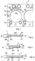
- the gasket A is a cylinder head gasket, and includes a cylinder bores Hc, water holes Hw, oil holes Ho and bolt holes Hb, as in the conventional gasket.
- the sealing mechanism of the invention is applied around the cylinder bore Hc, but the same sealing mechanisms may be formed around other holes, or for other gaskets.
- the gasket A comprises an upper plate A10, and a lower plate A11 situated under the upper plate A10.
- a thin graphite sheet A12 is attached or glued under the lower plate A11.
- the upper plate A10 includes a base section A10a extending substantially the entire area of the gasket A, a curved portion A10b to define the cylinder bore Hc, and a flange A10c.
- a space A13 is formed between the base section A10a and the flange A10c adjacent the curved portion A10b.
- the lower plate A11 situated under the upper plate A10 extends substantially the entire area of the gasket A.
- the thickness of the lower plate A11 may be equal to or thinner than the thickness of the upper plate.
- the lower plate A11 is made thinner than the upper plate A10.
- the lower plate A11 operates as a surface pressure regulation plate for the curved portion A10b and the flange A10c.
- the graphite sheet A12 is flexible, and has density of 0.8-1.8g/cm3 and thickness of 0.07mm.
- the graphite sheet A12 is used to fill small scratches of a cylinder block (not shown). Also, the graphite sheet helps sealing between the gasket and the cylinder block and allows the gasket to slide relative to the cylinder block.
- the graphite sheet must have a thickness between 30 and 100 microns. If the thickness is under 30 microns, the graphite sheet may not sufficiently fill small scratches of the cylinder block. If the thickness is over 100 microns, the graphite sheet may flow when high pressure and temperature are applied thereto, so that leakage may occur.
- the graphite sheet A12 is attached to the lower plate A11, the graphite sheet A12 is not directly exposed to the cylinder bore Hc. Namely, the graphite sheet A12 is not exposed to high temperature and pressure, so that the graphite sheet A12 does not flow in use.
- the graphite sheet A12 attached to the lower plate A11 is strongly pushed against the cylinder block. Since the cylinder block has small scratches on the outer surface thereof due to cutter trace, the graphite sheet A12 fills the small scratches to form a smooth surface.
- the gasket A can smoothly slide relative to the cylinder block when stress is formed therebetween according to expansion and contraction of the gasket and the cylinder block due to heat. Further, the graphite sheet A12 seals effectively relative to the cylinder block.
- the curved portion A10b When the gasket A is tightened, the curved portion A10b is compressed so that the space A13 is flattened. Accordingly, the curved portion A10b provides a resilient surface pressure for sealing around the cylinder hole. Also, since the thickness of the flange is thicker than the lower plate A11, a large surface pressure is formed at the flange A10c, so that the area around the cylinder bore Hc is securely sealed at the flange A10c.
- Fig. 3 shows a second embodiment B of a metal gasket of the invention.
- the gasket B comprises an upper plate B10 with a curved portion B10b and a flange B10c, a lower plate B11, and a graphite sheet B12, as in the gasket A.
- a metal plating B14 which is known in the art, is formed on an outer surface of the upper plate B10. Since the metal plating B14 is strong against heat, the metal plating B14 is entirely formed at the upper plate B10 contacting the cylinder head and exposing the cylinder bore Hc. Although the metal plating B14 can not completely fill small scratches on the cylinder head, the metal plating B14 helps sealing between the gasket and the cylinder head.
- Fig. 4 shows a third embodiment C of a steel laminate gasket of the invention.
- the gasket C comprises an upper plate C10 having a base section C10a, a curved portion C10b and a flange C10c, a lower plate C11, and a graphite sheet C12, as in the gasket A.
- the lower plate C11 is provided with a bead C11a around the cylinder bore Hc, and a graphite sheet C15 is situated between the upper plate C10 and the lower plate C11.
- the gasket C does not have a space adjacent the curved portion C10b, like a space A13 in the gasket A.
- the flange C10c and a part of the base section C10a form a solid portion around the cylinder bore Hc.
- the lower plate C11 is thinner than the upper plate C10, but the height of the bead C11a is made higher than the thickness of the flange C10c. Therefore, when the gasket C is assembled, the bead C11a projects outwardly from a lower surface of the flange C10c.
- the solid portion around the cylinder bore Hc i.e. the flange C10c and a part of the base portion C10a of the upper plate C10, is compressed.
- the solid portion is relatively wide, even if high tightening force is applied to the solid portion, the tightening force is not concentrated at one portion, so that relatively large tightening force can be applied to seal around the cylinder bore Hc.
- the graphite sheet C12 fills small scratches in the cylinder block.
- the graphite sheet C15 operates to help sliding between the upper and lower plates C10, C11 as well as sealing therebetween.
- the bead C11a is not completely compressed when the gasket C is tightened, because the flange C10c operates as a surface pressure regulation plate. Therefore, when the gasket vibrates, the bead can slide and vibrate according to the vibration of the engine to provide good sealing around the cylinder bore Hc.
- the gasket is formed of two metal plates to provide a thin gasket. Nevertheless, the gasket can securely seal around the hole of the engine together with the thin graphite sheet. Moreover, even if a gasket attaching portion of the engine part is not smoothly formed, the gasket can fill small scratches and provide good sealing between the engine part and the gasket.
Landscapes
- Engineering & Computer Science (AREA)
- General Engineering & Computer Science (AREA)
- Mechanical Engineering (AREA)
- Gasket Seals (AREA)
Applications Claiming Priority (2)
| Application Number | Priority Date | Filing Date | Title |
|---|---|---|---|
| US67389291A | 1991-03-25 | 1991-03-25 | |
| US673892 | 1991-03-25 |
Publications (2)
| Publication Number | Publication Date |
|---|---|
| EP0508017A1 true EP0508017A1 (de) | 1992-10-14 |
| EP0508017B1 EP0508017B1 (de) | 1996-01-10 |
Family
ID=24704520
Family Applications (1)
| Application Number | Title | Priority Date | Filing Date |
|---|---|---|---|
| EP19910309091 Expired - Lifetime EP0508017B1 (de) | 1991-03-25 | 1991-10-03 | Flachdichtung aus Metalllaminat mit einer Graphitschicht |
Country Status (4)
| Country | Link |
|---|---|
| EP (1) | EP0508017B1 (de) |
| JP (1) | JP2528069Y2 (de) |
| DE (1) | DE69116342T2 (de) |
| ES (1) | ES2082153T3 (de) |
Cited By (1)
| Publication number | Priority date | Publication date | Assignee | Title |
|---|---|---|---|---|
| EP1574761A1 (de) * | 2004-03-09 | 2005-09-14 | Ishikawa Gasket Co. Ltd. | Zylinderkopfdichtung |
Families Citing this family (4)
| Publication number | Priority date | Publication date | Assignee | Title |
|---|---|---|---|---|
| JP2001280502A (ja) * | 2000-03-29 | 2001-10-10 | Nippon Gasket Co Ltd | 単層金属製ガスケット |
| JP2007112940A (ja) * | 2005-10-21 | 2007-05-10 | Toyota Motor Corp | 部材間のシール構造及びガスケット |
| DE102007061084A1 (de) * | 2007-12-19 | 2009-07-02 | Federal-Mogul Sealing Systems Gmbh | Metallische Flachdichtung und Herstellverfahren |
| US10001214B2 (en) | 2013-11-26 | 2018-06-19 | Baker Hughes, A Ge Company, Llc | Seal arrangement and method of sealing |
Citations (3)
| Publication number | Priority date | Publication date | Assignee | Title |
|---|---|---|---|---|
| US4807892A (en) * | 1988-05-12 | 1989-02-28 | Ishikawa Gaskit Co., Ltd. | Steel laminate gasket with high sealing ability |
| US4834399A (en) * | 1986-11-10 | 1989-05-30 | Ishikawa Gasket Co., Ltd. | Steel laminate gasket |
| EP0328675A1 (de) * | 1987-07-29 | 1989-08-23 | Nippon Carbon Co., Ltd. | Dichtungsring für verbrennungsmotor |
Family Cites Families (2)
| Publication number | Priority date | Publication date | Assignee | Title |
|---|---|---|---|---|
| JPH082454Y2 (ja) * | 1988-06-17 | 1996-01-29 | 石川ガスケット株式会社 | シリンダヘッド金属ガスケット |
| JPH02107869A (ja) * | 1988-10-18 | 1990-04-19 | Nippon Riikuresu Kogyo Kk | メタルガスケットの製造方法 |
-
1991
- 1991-10-03 EP EP19910309091 patent/EP0508017B1/de not_active Expired - Lifetime
- 1991-10-03 ES ES91309091T patent/ES2082153T3/es not_active Expired - Lifetime
- 1991-10-03 DE DE1991616342 patent/DE69116342T2/de not_active Expired - Fee Related
-
1992
- 1992-03-25 JP JP1992015643U patent/JP2528069Y2/ja not_active Expired - Lifetime
Patent Citations (3)
| Publication number | Priority date | Publication date | Assignee | Title |
|---|---|---|---|---|
| US4834399A (en) * | 1986-11-10 | 1989-05-30 | Ishikawa Gasket Co., Ltd. | Steel laminate gasket |
| EP0328675A1 (de) * | 1987-07-29 | 1989-08-23 | Nippon Carbon Co., Ltd. | Dichtungsring für verbrennungsmotor |
| US4807892A (en) * | 1988-05-12 | 1989-02-28 | Ishikawa Gaskit Co., Ltd. | Steel laminate gasket with high sealing ability |
Cited By (2)
| Publication number | Priority date | Publication date | Assignee | Title |
|---|---|---|---|---|
| EP1574761A1 (de) * | 2004-03-09 | 2005-09-14 | Ishikawa Gasket Co. Ltd. | Zylinderkopfdichtung |
| US7311309B2 (en) | 2004-03-09 | 2007-12-25 | Ishikawa Gasket Co., Ltd. | Cylinder head gasket |
Also Published As
| Publication number | Publication date |
|---|---|
| JP2528069Y2 (ja) | 1997-03-05 |
| JPH0616769U (ja) | 1994-03-04 |
| ES2082153T3 (es) | 1996-03-16 |
| EP0508017B1 (de) | 1996-01-10 |
| DE69116342T2 (de) | 1996-05-30 |
| DE69116342D1 (de) | 1996-02-22 |
Similar Documents
| Publication | Publication Date | Title |
|---|---|---|
| US5435575A (en) | Steel laminate gasket | |
| US5076595A (en) | Steel laminate gasket | |
| US6250645B1 (en) | Gasket with annular sealing projection and groove | |
| US5150910A (en) | Gasket with soft and hard seal coatings | |
| EP0512178B2 (de) | Stahllaminatdichtung | |
| EP1275889A2 (de) | Zylinderkopfdichtung | |
| US5615898A (en) | Bead seal motorcycle gasket | |
| EP0500316B1 (de) | Metallaminatdichtung mit zwei Dichtungsringen | |
| US5893566A (en) | Metal laminate gasket with different coating layers | |
| EP0590944A1 (de) | Laminierte Metalldichtung mit einem Dichtungsabstandsstück | |
| US5634646A (en) | Metal laminate gasket with coating layer | |
| US5131668A (en) | Steel laminate gasket with seal protecting member | |
| EP0892199A2 (de) | Mehrlagenmetalldichtung mit breiten und schmalen Flanschabschnitten | |
| EP0833086B1 (de) | Metallabdichtung mit Deckschicht | |
| US5205569A (en) | Metal laminate gasket with graphite sheet | |
| EP0592140A1 (de) | Metalldichtung mit Kantenunterstützungswülsten | |
| US5395127A (en) | Metal laminate gasket with sealing grommet | |
| EP0508017B1 (de) | Flachdichtung aus Metalllaminat mit einer Graphitschicht | |
| US5961126A (en) | Metal gasket with peripheral bead | |
| US5215314A (en) | Gasket with main and auxiliary grommets | |
| US6126172A (en) | Metal gasket with partial support portion | |
| US5161498A (en) | Steel laminate type cylinder head gasket | |
| EP0486150B1 (de) | Geschichtete Stahlblechabdichtung mit Schutzteil | |
| EP0440831A1 (de) | Laminierte Stahldichtung | |
| EP0431227B1 (de) | Stahllaminatdichtung |
Legal Events
| Date | Code | Title | Description |
|---|---|---|---|
| PUAI | Public reference made under article 153(3) epc to a published international application that has entered the european phase |
Free format text: ORIGINAL CODE: 0009012 |
|
| AK | Designated contracting states |
Kind code of ref document: A1 Designated state(s): DE ES FR GB IT SE |
|
| 17P | Request for examination filed |
Effective date: 19921007 |
|
| 17Q | First examination report despatched |
Effective date: 19940419 |
|
| GRAA | (expected) grant |
Free format text: ORIGINAL CODE: 0009210 |
|
| AK | Designated contracting states |
Kind code of ref document: B1 Designated state(s): DE ES FR GB IT SE |
|
| ITF | It: translation for a ep patent filed | ||
| REF | Corresponds to: |
Ref document number: 69116342 Country of ref document: DE Date of ref document: 19960222 |
|
| ET | Fr: translation filed | ||
| REG | Reference to a national code |
Ref country code: ES Ref legal event code: FG2A Ref document number: 2082153 Country of ref document: ES Kind code of ref document: T3 |
|
| PLBE | No opposition filed within time limit |
Free format text: ORIGINAL CODE: 0009261 |
|
| STAA | Information on the status of an ep patent application or granted ep patent |
Free format text: STATUS: NO OPPOSITION FILED WITHIN TIME LIMIT |
|
| 26N | No opposition filed | ||
| PGFP | Annual fee paid to national office [announced via postgrant information from national office to epo] |
Ref country code: GB Payment date: 20011003 Year of fee payment: 11 |
|
| PGFP | Annual fee paid to national office [announced via postgrant information from national office to epo] |
Ref country code: SE Payment date: 20011005 Year of fee payment: 11 |
|
| PGFP | Annual fee paid to national office [announced via postgrant information from national office to epo] |
Ref country code: FR Payment date: 20011010 Year of fee payment: 11 |
|
| PGFP | Annual fee paid to national office [announced via postgrant information from national office to epo] |
Ref country code: DE Payment date: 20011015 Year of fee payment: 11 |
|
| PGFP | Annual fee paid to national office [announced via postgrant information from national office to epo] |
Ref country code: ES Payment date: 20011026 Year of fee payment: 11 |
|
| REG | Reference to a national code |
Ref country code: GB Ref legal event code: IF02 |
|
| PG25 | Lapsed in a contracting state [announced via postgrant information from national office to epo] |
Ref country code: GB Free format text: LAPSE BECAUSE OF NON-PAYMENT OF DUE FEES Effective date: 20021003 |
|
| PG25 | Lapsed in a contracting state [announced via postgrant information from national office to epo] |
Ref country code: SE Free format text: LAPSE BECAUSE OF NON-PAYMENT OF DUE FEES Effective date: 20021004 Ref country code: ES Free format text: LAPSE BECAUSE OF NON-PAYMENT OF DUE FEES Effective date: 20021004 |
|
| PG25 | Lapsed in a contracting state [announced via postgrant information from national office to epo] |
Ref country code: DE Free format text: LAPSE BECAUSE OF NON-PAYMENT OF DUE FEES Effective date: 20030501 |
|
| GBPC | Gb: european patent ceased through non-payment of renewal fee |
Effective date: 20021003 |
|
| EUG | Se: european patent has lapsed | ||
| PG25 | Lapsed in a contracting state [announced via postgrant information from national office to epo] |
Ref country code: FR Free format text: LAPSE BECAUSE OF NON-PAYMENT OF DUE FEES Effective date: 20030630 |
|
| REG | Reference to a national code |
Ref country code: FR Ref legal event code: ST |
|
| REG | Reference to a national code |
Ref country code: ES Ref legal event code: FD2A Effective date: 20031112 |
|
| PG25 | Lapsed in a contracting state [announced via postgrant information from national office to epo] |
Ref country code: IT Free format text: LAPSE BECAUSE OF NON-PAYMENT OF DUE FEES;WARNING: LAPSES OF ITALIAN PATENTS WITH EFFECTIVE DATE BEFORE 2007 MAY HAVE OCCURRED AT ANY TIME BEFORE 2007. THE CORRECT EFFECTIVE DATE MAY BE DIFFERENT FROM THE ONE RECORDED. Effective date: 20051003 |