EP0508159A2 - Distribution d'admission pour moteurs à combustion interne - Google Patents
Distribution d'admission pour moteurs à combustion interne Download PDFInfo
- Publication number
- EP0508159A2 EP0508159A2 EP92104461A EP92104461A EP0508159A2 EP 0508159 A2 EP0508159 A2 EP 0508159A2 EP 92104461 A EP92104461 A EP 92104461A EP 92104461 A EP92104461 A EP 92104461A EP 0508159 A2 EP0508159 A2 EP 0508159A2
- Authority
- EP
- European Patent Office
- Prior art keywords
- inlet
- opening
- intake
- valve
- load
- Prior art date
- Legal status (The legal status is an assumption and is not a legal conclusion. Google has not performed a legal analysis and makes no representation as to the accuracy of the status listed.)
- Granted
Links
- 238000002485 combustion reaction Methods 0.000 title claims abstract description 16
- 238000000034 method Methods 0.000 claims description 24
- 230000036961 partial effect Effects 0.000 claims description 3
- 230000003247 decreasing effect Effects 0.000 claims description 2
- 230000007704 transition Effects 0.000 claims 1
- 230000002349 favourable effect Effects 0.000 description 8
- 230000000694 effects Effects 0.000 description 5
- 239000000203 mixture Substances 0.000 description 4
- 238000009434 installation Methods 0.000 description 2
- 230000002829 reductive effect Effects 0.000 description 2
- 230000002411 adverse Effects 0.000 description 1
- 230000006835 compression Effects 0.000 description 1
- 238000007906 compression Methods 0.000 description 1
- 230000007423 decrease Effects 0.000 description 1
- 238000010586 diagram Methods 0.000 description 1
- 238000004880 explosion Methods 0.000 description 1
- 239000000446 fuel Substances 0.000 description 1
- 238000010438 heat treatment Methods 0.000 description 1
- 238000010297 mechanical methods and process Methods 0.000 description 1
- 210000000056 organ Anatomy 0.000 description 1
- 230000000717 retained effect Effects 0.000 description 1
- 230000001960 triggered effect Effects 0.000 description 1
Images


Classifications
-
- F—MECHANICAL ENGINEERING; LIGHTING; HEATING; WEAPONS; BLASTING
- F02—COMBUSTION ENGINES; HOT-GAS OR COMBUSTION-PRODUCT ENGINE PLANTS
- F02D—CONTROLLING COMBUSTION ENGINES
- F02D13/00—Controlling the engine output power by varying inlet or exhaust valve operating characteristics, e.g. timing
- F02D13/02—Controlling the engine output power by varying inlet or exhaust valve operating characteristics, e.g. timing during engine operation
- F02D13/0223—Variable control of the intake valves only
- F02D13/0234—Variable control of the intake valves only changing the valve timing only
-
- F—MECHANICAL ENGINEERING; LIGHTING; HEATING; WEAPONS; BLASTING
- F02—COMBUSTION ENGINES; HOT-GAS OR COMBUSTION-PRODUCT ENGINE PLANTS
- F02B—INTERNAL-COMBUSTION PISTON ENGINES; COMBUSTION ENGINES IN GENERAL
- F02B27/00—Use of kinetic or wave energy of charge in induction systems, or of combustion residues in exhaust systems, for improving quantity of charge or for increasing removal of combustion residues
-
- F—MECHANICAL ENGINEERING; LIGHTING; HEATING; WEAPONS; BLASTING
- F02—COMBUSTION ENGINES; HOT-GAS OR COMBUSTION-PRODUCT ENGINE PLANTS
- F02B—INTERNAL-COMBUSTION PISTON ENGINES; COMBUSTION ENGINES IN GENERAL
- F02B27/00—Use of kinetic or wave energy of charge in induction systems, or of combustion residues in exhaust systems, for improving quantity of charge or for increasing removal of combustion residues
- F02B27/02—Use of kinetic or wave energy of charge in induction systems, or of combustion residues in exhaust systems, for improving quantity of charge or for increasing removal of combustion residues the systems having variable, i.e. adjustable, cross-sectional areas, chambers of variable volume, or like variable means
- F02B27/0205—Use of kinetic or wave energy of charge in induction systems, or of combustion residues in exhaust systems, for improving quantity of charge or for increasing removal of combustion residues the systems having variable, i.e. adjustable, cross-sectional areas, chambers of variable volume, or like variable means characterised by the charging effect
- F02B27/0215—Oscillating pipe charging, i.e. variable intake pipe length charging
-
- F—MECHANICAL ENGINEERING; LIGHTING; HEATING; WEAPONS; BLASTING
- F02—COMBUSTION ENGINES; HOT-GAS OR COMBUSTION-PRODUCT ENGINE PLANTS
- F02B—INTERNAL-COMBUSTION PISTON ENGINES; COMBUSTION ENGINES IN GENERAL
- F02B27/00—Use of kinetic or wave energy of charge in induction systems, or of combustion residues in exhaust systems, for improving quantity of charge or for increasing removal of combustion residues
- F02B27/02—Use of kinetic or wave energy of charge in induction systems, or of combustion residues in exhaust systems, for improving quantity of charge or for increasing removal of combustion residues the systems having variable, i.e. adjustable, cross-sectional areas, chambers of variable volume, or like variable means
- F02B27/0226—Use of kinetic or wave energy of charge in induction systems, or of combustion residues in exhaust systems, for improving quantity of charge or for increasing removal of combustion residues the systems having variable, i.e. adjustable, cross-sectional areas, chambers of variable volume, or like variable means characterised by the means generating the charging effect
- F02B27/0289—Intake runners having multiple intake valves per cylinder
-
- F—MECHANICAL ENGINEERING; LIGHTING; HEATING; WEAPONS; BLASTING
- F02—COMBUSTION ENGINES; HOT-GAS OR COMBUSTION-PRODUCT ENGINE PLANTS
- F02B—INTERNAL-COMBUSTION PISTON ENGINES; COMBUSTION ENGINES IN GENERAL
- F02B29/00—Engines characterised by provision for charging or scavenging not provided for in groups F02B25/00, F02B27/00 or F02B33/00 - F02B39/00; Details thereof
- F02B29/08—Modifying distribution valve timing for charging purposes
- F02B29/083—Cyclically operated valves disposed upstream of the cylinder intake valve, controlled by external means
-
- F—MECHANICAL ENGINEERING; LIGHTING; HEATING; WEAPONS; BLASTING
- F02—COMBUSTION ENGINES; HOT-GAS OR COMBUSTION-PRODUCT ENGINE PLANTS
- F02D—CONTROLLING COMBUSTION ENGINES
- F02D13/00—Controlling the engine output power by varying inlet or exhaust valve operating characteristics, e.g. timing
- F02D13/02—Controlling the engine output power by varying inlet or exhaust valve operating characteristics, e.g. timing during engine operation
- F02D13/0253—Fully variable control of valve lift and timing using camless actuation systems such as hydraulic, pneumatic or electromagnetic actuators, e.g. solenoid valves
-
- F—MECHANICAL ENGINEERING; LIGHTING; HEATING; WEAPONS; BLASTING
- F02—COMBUSTION ENGINES; HOT-GAS OR COMBUSTION-PRODUCT ENGINE PLANTS
- F02D—CONTROLLING COMBUSTION ENGINES
- F02D13/00—Controlling the engine output power by varying inlet or exhaust valve operating characteristics, e.g. timing
- F02D13/02—Controlling the engine output power by varying inlet or exhaust valve operating characteristics, e.g. timing during engine operation
- F02D13/0257—Independent control of two or more intake or exhaust valves respectively, i.e. one of two intake valves remains closed or is opened partially while the other is fully opened
-
- F—MECHANICAL ENGINEERING; LIGHTING; HEATING; WEAPONS; BLASTING
- F02—COMBUSTION ENGINES; HOT-GAS OR COMBUSTION-PRODUCT ENGINE PLANTS
- F02B—INTERNAL-COMBUSTION PISTON ENGINES; COMBUSTION ENGINES IN GENERAL
- F02B75/00—Other engines
- F02B75/02—Engines characterised by their cycles, e.g. six-stroke
- F02B2075/022—Engines characterised by their cycles, e.g. six-stroke having less than six strokes per cycle
- F02B2075/027—Engines characterised by their cycles, e.g. six-stroke having less than six strokes per cycle four
-
- Y—GENERAL TAGGING OF NEW TECHNOLOGICAL DEVELOPMENTS; GENERAL TAGGING OF CROSS-SECTIONAL TECHNOLOGIES SPANNING OVER SEVERAL SECTIONS OF THE IPC; TECHNICAL SUBJECTS COVERED BY FORMER USPC CROSS-REFERENCE ART COLLECTIONS [XRACs] AND DIGESTS
- Y02—TECHNOLOGIES OR APPLICATIONS FOR MITIGATION OR ADAPTATION AGAINST CLIMATE CHANGE
- Y02T—CLIMATE CHANGE MITIGATION TECHNOLOGIES RELATED TO TRANSPORTATION
- Y02T10/00—Road transport of goods or passengers
- Y02T10/10—Internal combustion engine [ICE] based vehicles
- Y02T10/12—Improving ICE efficiencies
Definitions
- the invention relates to 4-stroke internal combustion engines with adjustable intake timing and individual intake manifolds per cylinder or per intake.
- the aim is to open the inlet element as effectively as possible (large amount per unit of time).
- the intake valve is opened as early as possible, however, taking into account the adverse effects of valve overlap when the exhaust valve is closed, and it is only closed when a maximum cylinder charge has been reached.
- An additional measure for increasing the cylinder charge is the use of an intake line per cylinder, the dimensions (length and diameter) of which are so coordinated that excess pressure is generated in front of the intake element by reflection towards the end of the closing of the intake valve.
- a disadvantage of this arrangement is the large length of the suction line, which often complicates installation in vehicles and similar devices.
- a good filling can be achieved by control elements with good flow behavior, that is to say with low flow resistance.
- 4-valve engines (2 intake valves) with flow-optimized channels have particularly favorable behavior at high speeds.
- the low flow resistance results in an inflow without large pressure drops.
- the cylinder filling is still supported due to the dynamic processes in the suction lines.
- the lines which are necessarily short due to the spatial conditions in engines, result in overpressure in front of the cylinder before the intake valves close due to reflection processes during the intake times which are short at high speeds. This increases the inflow of fresh cargo.
- the high flow velocities at high speeds ensure a sufficiently high level of turbulence in the cylinder, which is largely retained due to the short time available until the end of compression and leads to thermodynamically favorable, fast combustion.
- the low inflow speeds at the low speed also result in a low level of turbulence, which decreases further due to the longer dwell time until the start of combustion.
- the result is slow combustion with an unfavorable efficiency and an increased tendency to knock.
- the achievable torque at the low speeds is therefore unfavorable, which is particularly disadvantageous for vehicle engines and makes it difficult to adjust the drive for low fuel consumption.
- variable length suction pipes so that at low speed the effective dimension (eg suction pipe length) is adapted to the low speed by switching or other mechanical means.
- the effective dimension eg suction pipe length
- switching or other mechanical means With the limited installation space in vehicles, it is often difficult to accommodate the necessary voluminous dimensions.
- the effort involved is relatively high and the effects that can be achieved are limited.
- valve timing It is possible to adapt the valve timing to the requirements of an engine in the entire operating range through variable valve opening times. So far, this approach has been aimed at changing the intake closure at full load and at changing the opening time at partial load. The latter measure serves to reduce the cylinder charge for load control at part load. So far, a satisfactory solution for representing a high full load torque at low speeds in high-performance engines has not been possible either.
- the present invention has for its object to significantly improve the filling and combustion of a 4-stroke engine at high load, especially at full load, for low speeds, without having to do without good behavior at high speeds.
- the disadvantages of the known measures are to be avoided.
- the inlet member opens at low speeds and high torque (high load to full load) in the range of 10 to 90 degrees crank angle after the top dead center of the piston.
- high torque high load to full load
- a reduced pressure in the cylinder initially occurs during the downward movement of the piston, which causes an inflow at an increased speed when the inlet valve is opened late.
- a strong vacuum wave is triggered in the inlet channel, which is reflected at the intake manifold inlet as an overpressure wave and arrives at the appropriate dimensions of the intake manifold in good time before the inlet closes in front of the inlet member so that a high filling of the cylinder is ensured.
- the high entry velocities achieved also result in the high turbulence of the cylinder charge necessary for thermodynamically favorable rapid combustion.
- the inlet time is shortened, so that the length dimensions of the suction pipes can be smaller for convenient reloading. This improves the conditions for dimensioning and / or switching the suction system for a large speed range, and switching to a changed suction pipe geometry may even be superfluous under certain circumstances.
- the timing of the intake opening is steplessly or in stages so that the opening begins earlier with increasing speed. In this way, the process adapts the inflow conditions required for the high filling of the cylinder and for thermodynamically favorable combustion to the conditions of the respective speed for full load.
- the method can preferably be implemented with fully variable intake valve actuators.
- These control devices e.g. electromechanical according to DP 30 24 109) allow a stepless adjustment of the control time "intake opens” and the opening time to the speed to achieve the most favorable torque characteristics.
- one of the two intake valves can also be shut down with these fully variable actuating devices at lower speeds, so that the valve still working can interact with a channel of smaller cross-section and a length which is coordinated for lower speeds.
- the method can thus be used particularly well to achieve a wide speed range with high full load filling. The filling can be increased considerably beyond what is possible with the previously known control times.
- the use of valve actuators with speed-independent opening and closing speeds is particularly favorable. As a result, the opening impulse can be converted particularly effectively into reloading against inlet closing by opening late at low speeds.
- the method described is not limited to the use of fully variable actuating devices.
- Mechanical methods such as the rotation of two adjacent cams acting on a valve, can also be used to adjust the “inlet opening” control time.
- the opening of the inlet can take place independently of the opening of the inlet valve by actuating a control element in the inlet line which is located close to the inlet valve.
- FIG. 1 shows in the diagram the cylinder pressure as a function of the stroke volume for one working cycle of a 4-stroke reciprocating piston engine.
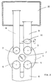
- Fig. 2 shows schematically and simplified a cross section through part of a 4-stroke reciprocating piston engine with four valves per cylinder.
- Fig. 3 shows two cams of a camshaft.
- FIG. 4 shows a simplified longitudinal section through a cylinder unit of a 4-stroke reciprocating piston engine.
- UT bottom dead center
- OT top dead center
- a working cycle of the 4-stroke reciprocating piston engine takes place between these two positions, shown by vertical dashed lines:
- the piston In the expansion phase marked phase I, the piston is moved to bottom dead center UT by the explosion pressure of the previously ignited fuel-air mixture.
- the outlet valve is opened (Ao) in the area of bottom dead center UT - usually just before it.
- phase II the so-called push-out phase
- the piston moves from UT to TDC and pushes the burned cylinder charge into the exhaust system when the exhaust valve is open.
- the exhaust valve In the area of top dead center OT, the exhaust valve is closed (As).
- the inlet valve is opened with a delay during the subsequent downward movement of the piston (Eo), so that a vacuum initially builds up in the cylinder.
- this negative pressure is abruptly reduced by the fresh mixture flowing in at high speed.
- phase III the piston sucks fresh mixture into the cylinder through the open inlet valve.
- Fig. 2 shows a schematic representation of a cross section through part of a reciprocating piston engine with four valves per cylinder. Shown is a cylinder 1 with two inlet valves 2 and 3 and two outlet valves 4 and 5. Furthermore, outlet duct 6 and spark plug 7 can be seen. Separate inlet ducts 8 and 9 with different cross sections and lengths end in the air collecting container 10. Inlet duct 9 has a flap 11, can be closed by the inlet channel 9.
- one of the two inlet valves can be shut down at lower speeds, so that the valve that is still working can interact with a channel of smaller cross-section and of a length dimensioned for lower speeds.
- the valve timing is changed so that the opening of the inlet is moved to a later time after top dead center, in such a way that the pressure wave initiated when opening the inlet at appropriate suction pipe length causes the cylinder to be reloaded before the inlet is closed.
- the opening of the inlet begins in a range of 10-90 degrees crank angle, preferably 20-60 degrees crank angle, after top dead center.
- the intake opening can be retarded continuously or in stages. It can also be advantageous that the inlet closing is set gradually or continuously to "early" at the same time as the inlet opening is retarded.
- control times can be adjusted by an electromagnetically controlled valve actuating device or by mechanical rotation of cam contours working together on a tappet. Hydraulic valve control can also be used to adjust the timing.
- a further advantageous possibility is that the opening of the inlet takes place independently of the opening of an inlet valve 2 or 3 by opening a control member 11 in the inlet line 9 which is close to the inlet valve 2 or 3.
- the inlet duct belonging to the displaced valve can also be designed separately and longer than the one belonging to the closed inlet.
- a part of a camshaft is shown in which two adjacent cams N, both of which act on the tappet for actuating an intake valve, can be rotated relative to one another by an angle W.
- the control times "inlet opening" can be suitably adjusted by rotating two adjacent cams.
- Fig. 4 shows a simplified and schematic longitudinal section through an internal combustion engine. Cylinder head 23 with exhaust valve 24 and intake valve 25 is seated on crankcase 21 with piston 22. The intake valve has an intake channel 26 which ends in an air collection container 27. The inlet channel 26 has an additional control member 28 for controlling "inlet opening” regardless of the opening of the inlet valve. It is favorable that the control member 28 is close to the inlet valve 25.
Landscapes
- Engineering & Computer Science (AREA)
- Chemical & Material Sciences (AREA)
- Combustion & Propulsion (AREA)
- Mechanical Engineering (AREA)
- General Engineering & Computer Science (AREA)
- Physics & Mathematics (AREA)
- Electromagnetism (AREA)
- Output Control And Ontrol Of Special Type Engine (AREA)
- Valve Device For Special Equipments (AREA)
Applications Claiming Priority (2)
| Application Number | Priority Date | Filing Date | Title |
|---|---|---|---|
| DE4111153 | 1991-04-06 | ||
| DE4111153A DE4111153A1 (de) | 1991-04-06 | 1991-04-06 | Einlasssteuerung fuer verbrennungskraftmaschinen |
Publications (3)
| Publication Number | Publication Date |
|---|---|
| EP0508159A2 true EP0508159A2 (fr) | 1992-10-14 |
| EP0508159A3 EP0508159A3 (en) | 1993-01-27 |
| EP0508159B1 EP0508159B1 (fr) | 1999-07-07 |
Family
ID=6428948
Family Applications (1)
| Application Number | Title | Priority Date | Filing Date |
|---|---|---|---|
| EP92104461A Expired - Lifetime EP0508159B1 (fr) | 1991-04-06 | 1992-03-16 | Distribution d'admission pour moteurs à combustion interne |
Country Status (3)
| Country | Link |
|---|---|
| US (1) | US5211146A (fr) |
| EP (1) | EP0508159B1 (fr) |
| DE (2) | DE4111153A1 (fr) |
Cited By (1)
| Publication number | Priority date | Publication date | Assignee | Title |
|---|---|---|---|---|
| EP1063394A2 (fr) | 1999-06-25 | 2000-12-27 | Nissan Motor Co., Ltd. | Moteur à combustion interne |
Families Citing this family (15)
| Publication number | Priority date | Publication date | Assignee | Title |
|---|---|---|---|---|
| DE19534876B4 (de) * | 1995-09-20 | 2006-11-09 | Fev Motorentechnik Gmbh | Verfahren zur Ermittlung der Ventilsteuerzeiten für eine maximale Zylinderfüllung an einer Kolbenbrennkraftmaschine |
| DE19613467A1 (de) * | 1996-04-04 | 1997-10-09 | Mann & Hummel Filter | Ansaugsystem für einen Verbrennungsmotor |
| SE519774C2 (sv) * | 1997-11-24 | 2003-04-08 | Volvo Ab | Förbränningsmotor som innefattar åtminstone en cylinder och individuella insugningskanaler |
| DE19843174C2 (de) * | 1998-09-21 | 2000-08-17 | Siemens Ag | Verfahren zum Steuern einer Brennkraftmaschine |
| US6431130B1 (en) * | 2000-08-29 | 2002-08-13 | Ford Global Technologies, Inc. | Torque control in an engine with a hybrid valvetrain |
| US6386156B1 (en) * | 2000-08-29 | 2002-05-14 | Ford Global Technologies, Inc. | Transitions among operating modes in an engine with a hybrid valvetrain |
| ITBO20010076A1 (it) * | 2001-02-13 | 2002-08-13 | Magneti Marelli Spa | Metodo per la stima del reperimento di un cilindro in un motore a combustione interna |
| AT412662B (de) * | 2002-11-12 | 2005-05-25 | Hoerbiger Kompressortech Hold | Schalteinheit im einlasssystem einer hubkolben-brennkraftmaschine |
| FR2852359B1 (fr) * | 2003-03-12 | 2005-05-20 | Procede de commande des soupapes d'un moteur a combustion interne | |
| US7320307B2 (en) * | 2005-09-12 | 2008-01-22 | Ford Global Technologies, Llc | Manifold pressure control for a variable event valvetrain |
| US7296550B2 (en) | 2005-09-12 | 2007-11-20 | Ford Global Technologies, Llc | Starting an engine having a variable event valvetrain |
| DE102010026658A1 (de) | 2010-07-09 | 2012-01-12 | Daimler Ag | Kraftfahrzeugnockenwellenverstellvorrichtung |
| DE102012018692A1 (de) * | 2012-09-21 | 2014-03-27 | Daimler Ag | Verfahren zum Betreiben einer zumindest ein Einlassventil aufweisenden Brennkraftmaschine, insbesondere eines Ottomotors |
| GB2506197B (en) * | 2012-09-25 | 2014-11-05 | Camcon Auto Ltd | Valve control systems for internal combustion engines and methods of operation thereof |
| DE102015202955A1 (de) * | 2015-02-18 | 2016-01-07 | Mtu Friedrichshafen Gmbh | Verfahren zum Betreiben einer Brennkraftmaschine, Verfahren zum Auslegen einer Brennkraftmaschine und Brennkraftmaschine |
Family Cites Families (17)
| Publication number | Priority date | Publication date | Assignee | Title |
|---|---|---|---|---|
| US1885796A (en) * | 1930-02-15 | 1932-11-01 | Eoulet Georges | Valve operating mechanism |
| US2057354A (en) * | 1935-11-04 | 1936-10-13 | Withers William Harold | Internal combustion engine automatic valve control |
| US2682260A (en) * | 1953-01-13 | 1954-06-29 | Robert H Lantz | Camshaft control mechanism |
| DE3024109A1 (de) * | 1980-06-27 | 1982-01-21 | Pischinger, Franz, Prof. Dipl.-Ing. Dr.Techn., 5100 Aachen | Elektromagnetisch arbeitende stelleinrichtung |
| JPS58117318A (ja) * | 1982-01-05 | 1983-07-12 | Mazda Motor Corp | エンジンの吸気装置 |
| JPS5946310A (ja) * | 1982-09-10 | 1984-03-15 | Mazda Motor Corp | エンジンのバルブタイミング制御装置 |
| JPS5946307A (ja) * | 1982-09-10 | 1984-03-15 | Mazda Motor Corp | エンジンのバルブタイミング制御装置 |
| DE3247916A1 (de) * | 1982-12-24 | 1984-06-28 | Robert Bosch Gmbh, 7000 Stuttgart | Vorrichtung zur steuerung der ventile einer brennkraftmaschine ueber eine nockenwelle |
| DE3401362C3 (de) * | 1983-02-04 | 1998-03-26 | Fev Motorentech Gmbh | Verfahren zur Steuerung von Viertakt-Kolbenbrennkraftmaschinen |
| JPS59188014A (ja) * | 1983-03-24 | 1984-10-25 | Mazda Motor Corp | エンジンのバルブタイミング制御装置 |
| JPH066887B2 (ja) * | 1983-07-25 | 1994-01-26 | マツダ株式会社 | エンジンのバルブタイミング制御装置 |
| DE3338870A1 (de) * | 1983-10-26 | 1985-05-09 | Bayerische Motoren Werke AG, 8000 München | Vorrichtung zum steuern des ladungswechsels bei brennkraftmaschinen |
| JPS6119632U (ja) * | 1984-07-10 | 1986-02-04 | トヨタ自動車株式会社 | 複吸気弁エンジン |
| US4703734A (en) * | 1985-03-06 | 1987-11-03 | Nissan Motor Co., Ltd. | Multi-valve internal combustion engine |
| US4667636A (en) * | 1985-03-22 | 1987-05-26 | Toyota Jidosha Kabushiki Kaisha | Fuel injection type internal combustion engine |
| US4759321A (en) * | 1985-06-24 | 1988-07-26 | Nissan Motor Co., Ltd. | Valve timing arrangement for internal combustion engine having multiple inlet valves per cylinder |
| JPH02181009A (ja) * | 1988-12-28 | 1990-07-13 | Isuzu Motors Ltd | 電磁駆動バルブ制御装置 |
-
1991
- 1991-04-06 DE DE4111153A patent/DE4111153A1/de not_active Ceased
-
1992
- 1992-03-16 EP EP92104461A patent/EP0508159B1/fr not_active Expired - Lifetime
- 1992-03-16 DE DE59209722T patent/DE59209722D1/de not_active Expired - Fee Related
- 1992-04-06 US US07/864,394 patent/US5211146A/en not_active Expired - Lifetime
Cited By (1)
| Publication number | Priority date | Publication date | Assignee | Title |
|---|---|---|---|---|
| EP1063394A2 (fr) | 1999-06-25 | 2000-12-27 | Nissan Motor Co., Ltd. | Moteur à combustion interne |
Also Published As
| Publication number | Publication date |
|---|---|
| EP0508159A3 (en) | 1993-01-27 |
| US5211146A (en) | 1993-05-18 |
| EP0508159B1 (fr) | 1999-07-07 |
| DE4111153A1 (de) | 1992-10-08 |
| DE59209722D1 (de) | 1999-08-12 |
Similar Documents
| Publication | Publication Date | Title |
|---|---|---|
| EP0663042B1 (fr) | Moteur a essence a quatre temps a commande hybride | |
| DE69703511T2 (de) | Brennkraftmaschine mit verstellbarem Ventilantrieb | |
| EP0508159B1 (fr) | Distribution d'admission pour moteurs à combustion interne | |
| EP0141165A2 (fr) | Dispositif de commande d'admission et d'échappement pour moteurs à combustion interne | |
| DE102016209957A1 (de) | Verfahren zum Betreiben einer Brennkraftmaschine und Brennkraftmaschine | |
| DE10359267B4 (de) | Verbrennungsmotor mit Ansaugventilen, variabler Ventilbetätigung und Zeitsteuerung | |
| WO2009030694A2 (fr) | Moteur à piston | |
| DE102004041607B4 (de) | Verbrennungsmotor | |
| DE102017206266A1 (de) | Verfahren zum Betreiben einer Brennkraftmaschine und Brennkraftmaschine | |
| DE102017101374B4 (de) | Verbrennungsmotor mit erhöhter verdichtung und mehrstufiger aufladung einschliesslich eines verdichters mit variabler geschwindigkeit | |
| EP1754872B1 (fr) | Moteur Otto avec soupapes à commande variable et fonctionnenment à cycle Atkinson | |
| EP1333158B1 (fr) | Moteur à quatre temps à injection directe et procédé de commande des soupapes | |
| DE102014006032A1 (de) | Verfahren zum Betrieb eines Verbrennungsmotors | |
| DE4341945A1 (de) | Hybridgesteuerter Viertakt-Ottomotor | |
| DE4414849A1 (de) | Fluidregelsystem für Kolbenmaschinen, insbesondere Verbrennungsmotoren nach dem Otto-Prozeß | |
| DE102013004800A1 (de) | Brennkraftmaschine und Verfahren zum Betreiben einer solchen Brennkraftmaschine | |
| WO2006042785A1 (fr) | Procede pour faire fonctionner un moteur a combustion interne | |
| DE102021005647A1 (de) | Verfahren zum Betreiben einer Verbrennungskraftmaschine, insbesondere eines Kraftfahrzeugs | |
| DE102020006622A1 (de) | Verfahren zum Betreiben einer Verbrennungskraftmaschine, insbesondere eines Kraftfahrzeugs | |
| DE102015009898A1 (de) | Verfahren zum Betreiben einer Hubkolben-Verbrennungskraftmaschine | |
| DE9209897U1 (de) | Zweitakt-Brennkraftmaschine | |
| DE102006014965A1 (de) | Brennkraftmaschine und Verfahren zum Betreiben dieser | |
| DE102015200598A1 (de) | Fremdgezündete Brennkraftmaschine mit variablem Ventiltrieb und Verfahren zum Betreiben einer derartigen Brennkraftmaschine | |
| DE202015106072U1 (de) | Brennkraftmaschine mit variablem Ventiltrieb | |
| DE4227261A1 (de) | Vorrichtung zur Erhöhung des Füllungsgrades von Saugmotoren |
Legal Events
| Date | Code | Title | Description |
|---|---|---|---|
| PUAI | Public reference made under article 153(3) epc to a published international application that has entered the european phase |
Free format text: ORIGINAL CODE: 0009012 |
|
| AK | Designated contracting states |
Kind code of ref document: A2 Designated state(s): DE FR GB IT |
|
| PUAL | Search report despatched |
Free format text: ORIGINAL CODE: 0009013 |
|
| AK | Designated contracting states |
Kind code of ref document: A3 Designated state(s): DE FR GB IT |
|
| 17P | Request for examination filed |
Effective date: 19930324 |
|
| 17Q | First examination report despatched |
Effective date: 19940225 |
|
| GRAG | Despatch of communication of intention to grant |
Free format text: ORIGINAL CODE: EPIDOS AGRA |
|
| GRAG | Despatch of communication of intention to grant |
Free format text: ORIGINAL CODE: EPIDOS AGRA |
|
| GRAH | Despatch of communication of intention to grant a patent |
Free format text: ORIGINAL CODE: EPIDOS IGRA |
|
| GRAH | Despatch of communication of intention to grant a patent |
Free format text: ORIGINAL CODE: EPIDOS IGRA |
|
| GRAA | (expected) grant |
Free format text: ORIGINAL CODE: 0009210 |
|
| AK | Designated contracting states |
Kind code of ref document: B1 Designated state(s): DE FR GB IT |
|
| PG25 | Lapsed in a contracting state [announced via postgrant information from national office to epo] |
Ref country code: IT Free format text: LAPSE BECAUSE OF FAILURE TO SUBMIT A TRANSLATION OF THE DESCRIPTION OR TO PAY THE FEE WITHIN THE PRE;WARNING: LAPSES OF ITALIAN PATENTS WITH EFFECTIVE DATE BEFORE 2007 MAY HAVE OCCURRED AT ANY TIME BEFORE 2007. THE CORRECT EFFECTIVE DATE MAY BE DIFFERENT FROM THE ONE RECORDED.SCRIBED TIME-LIMIT Effective date: 19990707 Ref country code: FR Free format text: LAPSE BECAUSE OF FAILURE TO SUBMIT A TRANSLATION OF THE DESCRIPTION OR TO PAY THE FEE WITHIN THE PRESCRIBED TIME-LIMIT Effective date: 19990707 Ref country code: GB Free format text: LAPSE BECAUSE OF FAILURE TO SUBMIT A TRANSLATION OF THE DESCRIPTION OR TO PAY THE FEE WITHIN THE PRESCRIBED TIME-LIMIT Effective date: 19990707 |
|
| REF | Corresponds to: |
Ref document number: 59209722 Country of ref document: DE Date of ref document: 19990812 |
|
| RAP2 | Party data changed (patent owner data changed or rights of a patent transferred) |
Owner name: FEV MOTORENTECHNIK GMBH |
|
| EN | Fr: translation not filed | ||
| GBV | Gb: ep patent (uk) treated as always having been void in accordance with gb section 77(7)/1977 [no translation filed] |
Effective date: 19990707 |
|
| PLBE | No opposition filed within time limit |
Free format text: ORIGINAL CODE: 0009261 |
|
| STAA | Information on the status of an ep patent application or granted ep patent |
Free format text: STATUS: NO OPPOSITION FILED WITHIN TIME LIMIT |
|
| 26N | No opposition filed | ||
| PGFP | Annual fee paid to national office [announced via postgrant information from national office to epo] |
Ref country code: DE Payment date: 20070320 Year of fee payment: 16 |
|
| PG25 | Lapsed in a contracting state [announced via postgrant information from national office to epo] |
Ref country code: DE Free format text: LAPSE BECAUSE OF NON-PAYMENT OF DUE FEES Effective date: 20081001 |