EP0508431A2 - Système de braquage des roues arrière pour un véhicule à quatre roues directrices - Google Patents
Système de braquage des roues arrière pour un véhicule à quatre roues directrices Download PDFInfo
- Publication number
- EP0508431A2 EP0508431A2 EP19920106178 EP92106178A EP0508431A2 EP 0508431 A2 EP0508431 A2 EP 0508431A2 EP 19920106178 EP19920106178 EP 19920106178 EP 92106178 A EP92106178 A EP 92106178A EP 0508431 A2 EP0508431 A2 EP 0508431A2
- Authority
- EP
- European Patent Office
- Prior art keywords
- rear wheel
- wheel turning
- control system
- vehicle
- slip control
- Prior art date
- Legal status (The legal status is an assumption and is not a legal conclusion. Google has not performed a legal analysis and makes no representation as to the accuracy of the status listed.)
- Granted
Links
Images




Classifications
-
- B—PERFORMING OPERATIONS; TRANSPORTING
- B60—VEHICLES IN GENERAL
- B60K—ARRANGEMENT OR MOUNTING OF PROPULSION UNITS OR OF TRANSMISSIONS IN VEHICLES; ARRANGEMENT OR MOUNTING OF PLURAL DIVERSE PRIME-MOVERS IN VEHICLES; AUXILIARY DRIVES FOR VEHICLES; INSTRUMENTATION OR DASHBOARDS FOR VEHICLES; ARRANGEMENTS IN CONNECTION WITH COOLING, AIR INTAKE, GAS EXHAUST OR FUEL SUPPLY OF PROPULSION UNITS IN VEHICLES
- B60K28/00—Safety devices for propulsion-unit control, specially adapted for, or arranged in, vehicles, e.g. preventing fuel supply or ignition in the event of potentially dangerous conditions
- B60K28/10—Safety devices for propulsion-unit control, specially adapted for, or arranged in, vehicles, e.g. preventing fuel supply or ignition in the event of potentially dangerous conditions responsive to conditions relating to the vehicle
- B60K28/16—Safety devices for propulsion-unit control, specially adapted for, or arranged in, vehicles, e.g. preventing fuel supply or ignition in the event of potentially dangerous conditions responsive to conditions relating to the vehicle responsive to, or preventing, spinning or skidding of wheels
-
- B—PERFORMING OPERATIONS; TRANSPORTING
- B62—LAND VEHICLES FOR TRAVELLING OTHERWISE THAN ON RAILS
- B62D—MOTOR VEHICLES; TRAILERS
- B62D7/00—Steering linkage; Stub axles or their mountings
- B62D7/06—Steering linkage; Stub axles or their mountings for individually-pivoted wheels, e.g. on king-pins
- B62D7/14—Steering linkage; Stub axles or their mountings for individually-pivoted wheels, e.g. on king-pins the pivotal axes being situated in more than one plane transverse to the longitudinal centre line of the vehicle, e.g. all-wheel steering
- B62D7/15—Steering linkage; Stub axles or their mountings for individually-pivoted wheels, e.g. on king-pins the pivotal axes being situated in more than one plane transverse to the longitudinal centre line of the vehicle, e.g. all-wheel steering characterised by means varying the ratio between the steering angles of the steered wheels
- B62D7/159—Steering linkage; Stub axles or their mountings for individually-pivoted wheels, e.g. on king-pins the pivotal axes being situated in more than one plane transverse to the longitudinal centre line of the vehicle, e.g. all-wheel steering characterised by means varying the ratio between the steering angles of the steered wheels characterised by computing methods or stabilisation processes or systems, e.g. responding to yaw rate, lateral wind, load, road condition
-
- B—PERFORMING OPERATIONS; TRANSPORTING
- B60—VEHICLES IN GENERAL
- B60T—VEHICLE BRAKE CONTROL SYSTEMS OR PARTS THEREOF; BRAKE CONTROL SYSTEMS OR PARTS THEREOF, IN GENERAL; ARRANGEMENT OF BRAKING ELEMENTS ON VEHICLES IN GENERAL; PORTABLE DEVICES FOR PREVENTING UNWANTED MOVEMENT OF VEHICLES; VEHICLE MODIFICATIONS TO FACILITATE COOLING OF BRAKES
- B60T8/00—Arrangements for adjusting wheel-braking force to meet varying vehicular or ground-surface conditions, e.g. limiting or varying distribution of braking force
- B60T8/32—Arrangements for adjusting wheel-braking force to meet varying vehicular or ground-surface conditions, e.g. limiting or varying distribution of braking force responsive to a speed condition, e.g. acceleration or deceleration
- B60T8/58—Arrangements for adjusting wheel-braking force to meet varying vehicular or ground-surface conditions, e.g. limiting or varying distribution of braking force responsive to a speed condition, e.g. acceleration or deceleration responsive to speed and another condition or to plural speed conditions
-
- B—PERFORMING OPERATIONS; TRANSPORTING
- B60—VEHICLES IN GENERAL
- B60T—VEHICLE BRAKE CONTROL SYSTEMS OR PARTS THEREOF; BRAKE CONTROL SYSTEMS OR PARTS THEREOF, IN GENERAL; ARRANGEMENT OF BRAKING ELEMENTS ON VEHICLES IN GENERAL; PORTABLE DEVICES FOR PREVENTING UNWANTED MOVEMENT OF VEHICLES; VEHICLE MODIFICATIONS TO FACILITATE COOLING OF BRAKES
- B60T2260/00—Interaction of vehicle brake system with other systems
- B60T2260/02—Active Steering, Steer-by-Wire
- B60T2260/022—Rear-wheel steering; Four-wheel steering
-
- B—PERFORMING OPERATIONS; TRANSPORTING
- B60—VEHICLES IN GENERAL
- B60W—CONJOINT CONTROL OF VEHICLE SUB-UNITS OF DIFFERENT TYPE OR DIFFERENT FUNCTION; CONTROL SYSTEMS SPECIALLY ADAPTED FOR HYBRID VEHICLES; ROAD VEHICLE DRIVE CONTROL SYSTEMS FOR PURPOSES NOT RELATED TO THE CONTROL OF A PARTICULAR SUB-UNIT
- B60W2552/00—Input parameters relating to infrastructure
- B60W2552/40—Coefficient of friction
Definitions
- This invention relates to a rear wheel turning system for a four-wheel-steered vehicle, and more particularly to a rear wheel turning system for a four-wheel-steered vehicle provided with an anti-skid brake system and/or a traction control system.
- ABS anti-skid brake system
- a traction control system (will be abbreviated as a TRC system hereinbelow) which detects slip of the driving wheels during starting or hard acceleration and controls the throttle opening of the engine and/or the brake fluid pressure to the driving wheels so that the friction between the road surface and the driving wheels is maximized, thereby obtaining an optimal road gripping force of the driving wheels during starting or hard acceleration.
- the rear wheel turning characteristic when the rear wheel turning characteristic is changed according to whether the ABS is operating, the rear wheel turning characteristic can be frequently changed to cause hunting in the case where the brakes are applied on a road whose friction coefficient changes frequently, thereby deteriorating the running stability of the vehicle.
- the primary object of the present invention is to provide a rear wheel turning system for a four-wheel-steered vehicle having a slip control system such as an ABS or a TRC which can ensure running stability of the vehicle when operation of the slip control system is interrupted.
- a slip control system such as an ABS or a TRC which can ensure running stability of the vehicle when operation of the slip control system is interrupted.
- a rear wheel turning system for a four-wheel-steered vehicle provided with a slip control system such as an anti-skid brake system or a traction control system
- a slip control system such as an anti-skid brake system or a traction control system
- a rear wheel turning mechanism which turns rear wheels of the vehicle in response to turning of front wheels of the vehicle according to a predetermined rear wheel turning characteristic
- a rear wheel turning characteristic correcting means which corrects the rear, wheel turning characteristic substantially in response to initiation of operation of the slip control system
- a correction holding means which holds the corrected rear wheel turning characteristic until a predetermined condition is satisfied after interruption of the operation of the slip control system.
- the correction holding means holds the corrected rear wheel turning characteristic until a predetermined time lapses after interruption of the operation of the slip control system.
- the correction holding means may do so until the deceleration of the vehicle continues to be smaller than a predetermined value for a predetermined time with the brake pedal pushed down.
- the correction holding means may do so until the acceleration of the vehicle continues to be larger than a predetermined value for a predetermined time with the accelerator pedal pushed down.
- a rear wheel turning system for a four-wheel-steered vehicle provided with a slip control system such as an anti-skid brake system or a traction control system
- a slip control system such as an anti-skid brake system or a traction control system
- a first correcting means which corrects the rear wheel turning characteristic substantially in response to initiation of operation of the slip control system
- a second correcting means which corrects the rear wheel turning characteristic on the basis of the road surface condition determined during operation of the slip control system
- a correction holding means which holds the rear wheel turning characteristic which has been corrected on the basis of the road surface condition after the operation of the slip control system is interrupted.
- left and right front wheels 2FL and 2FR of a vehicle 1 are turned by a front wheel turning mechanism A and left and right rear wheels 2RL and 2RR of the vehicle 1 are turned by a rear wheel turning mechanism B.
- the front wheel turning mechanism A comprises a pair of knuckle arms 3FL and 3FR, a pair of tie rods 4FL and 4FR and a relay rod 5F which connects the tie rods 4FL and 4FR.
- the front wheel turning mechanism A is connected to a steering wheel 8 by way of a steering mechanism C having a rack (not shown) provided on the relay rod 5F and a pinion 6 provided on a steering shaft 7.
- the rear wheel turning mechanism B comprises a pair of knuckle arms 3RL and 3RR, a pair of tie rods 4RL and 4RR, a relay rod 5R which connects the tie rods 4RL and 4RR, a servomotor 10, and a transmission mechanism 11 which transmits the driving force of the servomotor 10 to the relay rod 5R.
- the rear wheel turning mechanism B has a fail-safe mechanism comprising a clutch 12 for connecting and disconnecting the servomotor 10 and the relay rod 5R and a neutralizing means 9 having a spring 9a which urges the relay rod 5R to the neutral position in which it holds the rear wheels 2RL and 2RR in the straight ahead position.
- a fail-safe mechanism comprising a clutch 12 for connecting and disconnecting the servomotor 10 and the relay rod 5R and a neutralizing means 9 having a spring 9a which urges the relay rod 5R to the neutral position in which it holds the rear wheels 2RL and 2RR in the straight ahead position.
- the vehicle 1 is further provided with a steering angle sensor 13 for detecting the turning angle of the steering wheel 8, a vehicle speed sensor 14 which detects the speed of the vehicle, an encoder 17 for detecting the angular position of the servomotor 10, and a rear wheel turning angle sensor 18 which detects the turning angle of the rear wheels 2RL and 2RR through the position of the relay rod 5R.
- a rear wheel control unit U1 controls the servomotor 10 on the basis of the outputs of the steering angle sensor 13, the vehicle speed sensor 14, the encoder 17 and the rear wheel turning angle sensor 18.
- the rear wheel control unit U1 controls the servomotor 10 according to the target rear wheel turning angle to turn the rear wheels 2RL and 2RR while watching the positions of the servomotor 10 and the relay rod 5R respectively by way of the encoder 17 and the rear wheel turning angle sensor 18.
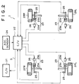
- the vehicle 1 is provided with an anti-skid brake system shown in Figure 2 as the slip control system.
- each of the wheels 2FL, 2FR, 2RL and 2RR is provided with a brake 23 comprising a disk rotor 23a which rotates together wish the wheel and a caliper 23b which brakes the disk rotor 23a when applied with brake fluid pressure.
- the ABS controls the brake fluid pressure applied to each brake 23 from the brake fluid pressure applied to the other brakes 23.
- the ABS comprises an acceleration sensor 24 for detecting deceleration of the vehicle 1, wheel speed sensors 25 each for detecting the wheel speed of each wheel, an ABS control unit U2 which receives the outputs of the sensors 24 and 25, hydraulic pressure control valves 26 which control the brake fluid pressures applied to the respective brakes 23 on the basis of control signals given to the respective hydraulic pressure control valves 26 from the ABS control unit U2, and a hydraulic unit (not shown) which supplies brake fluid to the hydraulic pressure control valves 26 at a regulated pressure.
- the ABS control unit U2 determines, on the basis of predetermined one of the rotational speeds of the wheels 2FL, 2FR, 2RL and 2RR detected by the wheel speeds sensors 25, e.g., the highest speed, a reference rotational speed at which a predetermined slip ratio between the road surface and the wheel is obtained and a maximum braking takes place for a given vehicle speed. Then the ABS control unit U2 compares the respective rotational speeds with the reference rotational speed and controls the brake fluid pressure to the respective brakes 23 to prevent skid or lock of each wheel by way of the hydraulic pressure valves 26 .
- the ABS control unit U2 outputs to the rear wheel control unit U1 a signal S which represents the friction coefficient ⁇ of the road surface and whether the ABS is operating, and the rear wheel control unit U1 changes the rear wheel turning angle ratio characteristic according to the operating condition of the ABS for the respective brakes 23.
- Figure 3 shows the rear wheel turning angle ratio characteristics set by the rear wheel turning angle control system provided in the rear wheel control unit U1.
- Curve I represents a normal rear wheel turning angle ratio characteristic which is set according to the vehicle speed V when the ABS is not operating
- curve II represents a corrected rear wheel turning angle ratio characteristic which is set when the ABS is operating and is obtained by correcting the normal rear wheel turning angle ratio characteristic curve I with a correction value KA which is a positive constant.
- the vehicle 1 is supposed to be a front-engine rear-drive vehicle, and the correction value KA is added to a rear wheel turning angle ratio K given according to the normal rear wheel turning angle ratio characteristic curve I so that the rear wheel turning angle ratio characteristic curve shifts toward the same phase side.
- the rear wheel turning angle ratio K is defined to be positive in the same phase and negative in the reverse phase.
- the correction value KA is subtracted from a rear wheel turning angle ratio K given according to the normal rear wheel turning angle ratio characteristic curve I so that the rear wheel turning angle ratio characteristic curve shifts toward the reverse phase side as represented by curve II'.
- the corrected rear wheel turning angle ratio characteristic represented by the curve II which is set when the ABS is operating is further corrected with a friction-based correction value KB so that the rear wheel turning angle ratio characteristic curve shifts toward the same phase side as represented by curve III.
- the friction-based correction value KB is changed according to the friction coefficient ⁇ of the road surface determined by the ABS control unit U2 as shown in Figure 4. As can be seen from Figure 4, when the friction coefficient ⁇ of the road surface is higher than the value at which the deceleration of the vehicle body upon application of the brakes is, for instance, -0.2G, the friction-based correction value KB is nullified. Normally the correction value KA is larger than the correction value KB in absolute value.
- the correction of the rear wheel turning angle ratio characteristic with the correction value KA is not released soon after interruption of the operation of the ABS until the running condition of the vehicle is stabilized. That is, a timer is set upon interruption of the operation of the ABS and the correction of the rear wheel turning angle ratio characteristic with the correction value KA is held for a predetermined time after interruption of the operation of the ABS until the timer times out, though it is released when the running of the vehicle is stabilized or the vehicle speed approaches zero while the brake pedal is pushed even before the timer times out.
- the correction with the friction-based correction value KB is not released even after release of the correction with the correction value KA and the friction-based correction value KB is up-dated on the basis of the friction coefficient ⁇ of the road surface determined in the next operation of the ABS.
- the rear wheel turning angle ratio correction routine executed by the rear wheel control unit U1 will be described with reference to the flow charts shown in Figures 5 and 6, hereinbelow.
- step S1 the rear wheel control unit U1 corrects the rear wheel turning angle ratio K set in step S2 with the correction value KA and sets the flag F to 1. (steps S5 and S6) Then the rear wheel control unit U1 returns to step S1.
- step S7 the rear wheel control unit U1 reads the friction coefficient ⁇ of the road surface.
- step S8 the rear wheel control unit U1 determines the friction-based correction value KB according to the map shown in Figure 4 and adds it to the corrected rear wheel turning angle ratio (K ⁇ KA+KB).
- step S9 the rear wheel control unit U1 determines whether the operation of the ABS has been interrupted. When it is determined that the operation of the ABS has not been interrupted, the rear wheel control unit U1 returns to step S1.
- step S9 when it is determined in step S9 that the operation of the ABS has been interrupted, the rear wheel control unit U1 sets a timer which times out a predetermined time (one to two minutes) after. (step S10) Then in step S11, the rear wheel control unit U1 determines whether the timer has timed out, and when it is determined that the timer has timed out, the rear wheel control unit U1 nullifies the correction value KA and returns after setting the flag F to 0. (steps S12 and S13) When it is determined in step S11 that the timer has not timed out, the rear wheel control unit U1 determines in step S14 whether the brake pedal has been pushed (whether a brake switch is on).
- the rear wheel control unit U1 nullifies the correction value KA and sets the flag F to 0 even before the timer times out (steps S12 and S13) so long as the deceleration
- the rear wheel turning system of this embodiment is mechanically substantially the same as the preceding embodiment and mainly differs therefrom in the operation of the rear wheel control unit U1.
- TRC light braking of the driving wheels and/or throttle control of the engine is effected in order to prevent slip of the driving wheels during start or hard acceleration of the vehicle.
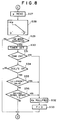
- the rear wheel turning angle ratio correction routine to be executed by the rear wheel control unit U1 in this embodiment will be described with reference to the flow chart shown in Figures 7 and 8, hereinbelow.
- Steps S21 to S36 in the flow chart shown in Figures 7 and 8 are the same as steps S1 to S16 in the flow chart shown in Figures 5 and 6 except that the question in step S24 is whether the TRC is operating, the question in step S29 is whether the TRC is not operating, the question in step S34 is whether the accelerator is pushed down (whether an accelerator switch is on), the question in step S35 is whether the acceleration
- the correction of the rear wheel turning angle ratio characteristic with the correction value KA is released soon after interruption of the operation of the ABS but the correction with the friction-based correction value KB is not released even after release of the correction with the correction value KA and the friction-based correction value KB is up-dated on the basis of the friction coefficient ⁇ of the road surface determined in the next operation of the ABS.
- the friction-based correction value KB is nullified.
- the rear wheel control unit U1 first reads the vehicle speed V and sets the rear wheel turning angle ratio K according to the curve I (in Figure 3) on the basis of the vehicle speed V. (steps S41 and S42) Then the rear wheel control unit U1 determines in step S43 whether the ABS is operating. When it is determined that the ABS is not operating, the rear wheel control unit U1 returns to step S41 after setting the rear wheel turning angle ratio KT to K in step S48. Otherwise the rear wheel control unit U1 sets the correction value KA. (step S44) In step S45, the rear wheel control unit U1 reads the friction coefficient ⁇ of the road surface.
- step S46 the rear wheel control unit U1 determines the friction-based correction value KB according to the map shown in Figure 4.
- step S47 the rear wheel control unit U1 determines whether the operation of the ABS has been interrupted. When it is determined that the operation of the ABS has not been interrupted, the rear wheel control unit U1 returns to step S41 after setting the rear wheel turning angle ratio KT to K+KA+KB in step S48.
- step S47 when it is determined in step S47 that the operation of the ABS has been interrupted, the rear wheel control unit U1 nullifies, the correction value KA in step S49 and then determines in step S50 whether the absolute value of the lateral acceleration G is not smaller than a predetermined value Go.
- the rear wheel control unit U1 sets the rear wheel turning angle ratio KT to K+KB in step S48.
- the value of the friction-based correction value KB is up-dated on the basis of the determination in step S46 in the next operation of the ABS.
- the rear wheel control unit U1 sets the rear wheel turning angle ratio KT to K in step S48.
- the present invention is applied to a four-wheel-steered vehicle provided with an ABS
- the present invention can also be applied to a four-wheel-steered vehicle provided with a TRC system.
Landscapes
- Engineering & Computer Science (AREA)
- Transportation (AREA)
- Mechanical Engineering (AREA)
- Chemical & Material Sciences (AREA)
- Combustion & Propulsion (AREA)
- Physics & Mathematics (AREA)
- Mathematical Physics (AREA)
- Theoretical Computer Science (AREA)
- Regulating Braking Force (AREA)
- Steering Control In Accordance With Driving Conditions (AREA)
- Steering-Linkage Mechanisms And Four-Wheel Steering (AREA)
Applications Claiming Priority (4)
| Application Number | Priority Date | Filing Date | Title |
|---|---|---|---|
| JP10342991A JP3003717B2 (ja) | 1991-04-09 | 1991-04-09 | 車両の後輪操舵装置 |
| JP103429/91 | 1991-04-09 | ||
| JP10343091A JP3007439B2 (ja) | 1991-04-09 | 1991-04-09 | 車両の後輪操舵装置 |
| JP103430/91 | 1991-04-09 |
Publications (3)
| Publication Number | Publication Date |
|---|---|
| EP0508431A2 true EP0508431A2 (fr) | 1992-10-14 |
| EP0508431A3 EP0508431A3 (en) | 1993-01-07 |
| EP0508431B1 EP0508431B1 (fr) | 1995-11-15 |
Family
ID=26444064
Family Applications (1)
| Application Number | Title | Priority Date | Filing Date |
|---|---|---|---|
| EP92106178A Expired - Lifetime EP0508431B1 (fr) | 1991-04-09 | 1992-04-09 | Système de braquage des roues arrière pour un véhicule à quatre roues directrices |
Country Status (3)
| Country | Link |
|---|---|
| EP (1) | EP0508431B1 (fr) |
| KR (1) | KR960005851B1 (fr) |
| DE (1) | DE69206025T2 (fr) |
Cited By (3)
| Publication number | Priority date | Publication date | Assignee | Title |
|---|---|---|---|---|
| WO2004080783A1 (fr) * | 2003-03-13 | 2004-09-23 | Knorr-Bremse Systeme für Nutzfahrzeuge GmbH | Systeme de direction pour vehicules comprenant une paire de roues pouvant etre dirigees librement par des forces laterales |
| WO2015060752A1 (fr) * | 2013-10-21 | 2015-04-30 | Volvo Truck Corporation | Système de direction de roue permettant de commander un angle de direction d'une seconde paire de roues orientables d'un véhicule |
| CN120091948A (zh) * | 2022-12-31 | 2025-06-03 | 深圳引望智能技术有限公司 | 后轮回正装置、转向系统、车辆、控制方法和装置 |
Family Cites Families (3)
| Publication number | Priority date | Publication date | Assignee | Title |
|---|---|---|---|---|
| CA1269335A (fr) * | 1985-06-17 | 1990-05-22 | Shigeki Furutani | Systeme de direction sur quatre roues pour vehicule |
| JP2685205B2 (ja) * | 1988-03-14 | 1997-12-03 | マツダ株式会社 | 車両の後輪操舵装置 |
| JPH01237265A (ja) * | 1988-03-17 | 1989-09-21 | Honda Motor Co Ltd | 前後輪操舵車両 |
-
1992
- 1992-04-08 KR KR1019920005811A patent/KR960005851B1/ko not_active Expired - Fee Related
- 1992-04-09 EP EP92106178A patent/EP0508431B1/fr not_active Expired - Lifetime
- 1992-04-09 DE DE69206025T patent/DE69206025T2/de not_active Expired - Fee Related
Cited By (4)
| Publication number | Priority date | Publication date | Assignee | Title |
|---|---|---|---|---|
| WO2004080783A1 (fr) * | 2003-03-13 | 2004-09-23 | Knorr-Bremse Systeme für Nutzfahrzeuge GmbH | Systeme de direction pour vehicules comprenant une paire de roues pouvant etre dirigees librement par des forces laterales |
| US7975800B2 (en) | 2003-03-13 | 2011-07-12 | Knorr-Bremse Systeme Fuer Nutzfahrzeugu GmbH | Steering device for vehicles having a pair of wheels which can be steered freely by means of lateral forces |
| WO2015060752A1 (fr) * | 2013-10-21 | 2015-04-30 | Volvo Truck Corporation | Système de direction de roue permettant de commander un angle de direction d'une seconde paire de roues orientables d'un véhicule |
| CN120091948A (zh) * | 2022-12-31 | 2025-06-03 | 深圳引望智能技术有限公司 | 后轮回正装置、转向系统、车辆、控制方法和装置 |
Also Published As
| Publication number | Publication date |
|---|---|
| DE69206025T2 (de) | 1996-07-25 |
| EP0508431B1 (fr) | 1995-11-15 |
| KR920019601A (ko) | 1992-11-19 |
| KR960005851B1 (ko) | 1996-05-03 |
| DE69206025D1 (de) | 1995-12-21 |
| EP0508431A3 (en) | 1993-01-07 |
Similar Documents
| Publication | Publication Date | Title |
|---|---|---|
| JP3617680B2 (ja) | 4輪駆動車のトラクション制御装置 | |
| EP1424263B1 (fr) | Dispositif de contrôle de direction d'un véhicule | |
| EP0379143B1 (fr) | Dispositif de braquage des roues arrières d'un véhicule | |
| JP4396002B2 (ja) | 車輌のトラクション制御装置 | |
| KR100281613B1 (ko) | 차량의 거동 제어장치 | |
| US20020007239A1 (en) | Lane keep control for vehicle | |
| US6064930A (en) | Yaw moment control system in vehicle | |
| US7493982B2 (en) | Control device for a four-wheel drive vehicle | |
| JPH0613287B2 (ja) | 車両用制動力制御装置 | |
| US5184298A (en) | Rear wheel steering system for vehicle | |
| EP0523698B1 (fr) | Système de commande du couple des roues motrices d'un véhicule | |
| JP4207698B2 (ja) | 車両の横転防止装置 | |
| EP0508431B1 (fr) | Système de braquage des roues arrière pour un véhicule à quatre roues directrices | |
| JP2707574B2 (ja) | 車両の旋回制御装置 | |
| JP3007439B2 (ja) | 車両の後輪操舵装置 | |
| JP2001082201A (ja) | 車輌の挙動制御装置 | |
| JP3003717B2 (ja) | 車両の後輪操舵装置 | |
| JP3007438B2 (ja) | 車両の後輪操舵装置 | |
| JP2001082200A (ja) | 車輌の挙動制御装置 | |
| JP3003716B2 (ja) | 車両の後輪操舵装置 | |
| JPH05278625A (ja) | 車両の後輪操舵装置 | |
| JP3078915B2 (ja) | 車両の後輪操舵装置 | |
| JPH0672171A (ja) | 四輪駆動車の駆動力配分装置 | |
| JPH05278593A (ja) | 車両の後輪操舵装置 | |
| JPS63166664A (ja) | 前後輪操舵車の後輪操舵制御装置 |
Legal Events
| Date | Code | Title | Description |
|---|---|---|---|
| PUAI | Public reference made under article 153(3) epc to a published international application that has entered the european phase |
Free format text: ORIGINAL CODE: 0009012 |
|
| AK | Designated contracting states |
Kind code of ref document: A2 Designated state(s): DE FR GB |
|
| RIN1 | Information on inventor provided before grant (corrected) |
Inventor name: NOHDA, HIROYUKI Inventor name: MURAI, TAKESHI Inventor name: OHMURA, HIROSHI Inventor name: KAGEYAMA, FUMIO Inventor name: AKITA, RYUYA |
|
| PUAL | Search report despatched |
Free format text: ORIGINAL CODE: 0009013 |
|
| AK | Designated contracting states |
Kind code of ref document: A3 Designated state(s): DE FR GB |
|
| 17P | Request for examination filed |
Effective date: 19930217 |
|
| 17Q | First examination report despatched |
Effective date: 19940203 |
|
| GRAA | (expected) grant |
Free format text: ORIGINAL CODE: 0009210 |
|
| AK | Designated contracting states |
Kind code of ref document: B1 Designated state(s): DE FR GB |
|
| REF | Corresponds to: |
Ref document number: 69206025 Country of ref document: DE Date of ref document: 19951221 |
|
| ET | Fr: translation filed | ||
| PLBE | No opposition filed within time limit |
Free format text: ORIGINAL CODE: 0009261 |
|
| STAA | Information on the status of an ep patent application or granted ep patent |
Free format text: STATUS: NO OPPOSITION FILED WITHIN TIME LIMIT |
|
| 26N | No opposition filed | ||
| PGFP | Annual fee paid to national office [announced via postgrant information from national office to epo] |
Ref country code: GB Payment date: 19970401 Year of fee payment: 6 |
|
| PGFP | Annual fee paid to national office [announced via postgrant information from national office to epo] |
Ref country code: FR Payment date: 19970409 Year of fee payment: 6 |
|
| PG25 | Lapsed in a contracting state [announced via postgrant information from national office to epo] |
Ref country code: GB Free format text: LAPSE BECAUSE OF NON-PAYMENT OF DUE FEES Effective date: 19980409 |
|
| PG25 | Lapsed in a contracting state [announced via postgrant information from national office to epo] |
Ref country code: FR Free format text: THE PATENT HAS BEEN ANNULLED BY A DECISION OF A NATIONAL AUTHORITY Effective date: 19980430 |
|
| GBPC | Gb: european patent ceased through non-payment of renewal fee |
Effective date: 19980409 |
|
| REG | Reference to a national code |
Ref country code: FR Ref legal event code: ST |
|
| PGFP | Annual fee paid to national office [announced via postgrant information from national office to epo] |
Ref country code: DE Payment date: 20020417 Year of fee payment: 11 |
|
| PG25 | Lapsed in a contracting state [announced via postgrant information from national office to epo] |
Ref country code: DE Free format text: LAPSE BECAUSE OF NON-PAYMENT OF DUE FEES Effective date: 20031101 |