EP0508569A1 - Mécanisme vis-écron à accouplement synchronique - Google Patents
Mécanisme vis-écron à accouplement synchronique Download PDFInfo
- Publication number
- EP0508569A1 EP0508569A1 EP92301117A EP92301117A EP0508569A1 EP 0508569 A1 EP0508569 A1 EP 0508569A1 EP 92301117 A EP92301117 A EP 92301117A EP 92301117 A EP92301117 A EP 92301117A EP 0508569 A1 EP0508569 A1 EP 0508569A1
- Authority
- EP
- European Patent Office
- Prior art keywords
- nut
- lifting sleeve
- screw
- screw stem
- sleeve
- Prior art date
- Legal status (The legal status is an assumption and is not a legal conclusion. Google has not performed a legal analysis and makes no representation as to the accuracy of the status listed.)
- Granted
Links
Images


Classifications
-
- F—MECHANICAL ENGINEERING; LIGHTING; HEATING; WEAPONS; BLASTING
- F16—ENGINEERING ELEMENTS AND UNITS; GENERAL MEASURES FOR PRODUCING AND MAINTAINING EFFECTIVE FUNCTIONING OF MACHINES OR INSTALLATIONS; THERMAL INSULATION IN GENERAL
- F16H—GEARING
- F16H25/00—Gearings comprising primarily only cams, cam-followers and screw-and-nut mechanisms
- F16H25/18—Gearings comprising primarily only cams, cam-followers and screw-and-nut mechanisms for conveying or interconverting oscillating or reciprocating motions
- F16H25/20—Screw mechanisms
- F16H25/2025—Screw mechanisms with means to disengage the nut or screw from their counterpart; Means for connecting screw and nut for stopping reciprocating movement
-
- B—PERFORMING OPERATIONS; TRANSPORTING
- B23—MACHINE TOOLS; METAL-WORKING NOT OTHERWISE PROVIDED FOR
- B23Q—DETAILS, COMPONENTS, OR ACCESSORIES FOR MACHINE TOOLS, e.g. ARRANGEMENTS FOR COPYING OR CONTROLLING; MACHINE TOOLS IN GENERAL CHARACTERISED BY THE CONSTRUCTION OF PARTICULAR DETAILS OR COMPONENTS; COMBINATIONS OR ASSOCIATIONS OF METAL-WORKING MACHINES, NOT DIRECTED TO A PARTICULAR RESULT
- B23Q5/00—Driving or feeding mechanisms; Control arrangements therefor
- B23Q5/22—Feeding members carrying tools or work
- B23Q5/34—Feeding other members supporting tools or work, e.g. saddles, tool-slides, through mechanical transmission
- B23Q5/38—Feeding other members supporting tools or work, e.g. saddles, tool-slides, through mechanical transmission feeding continuously
- B23Q5/40—Feeding other members supporting tools or work, e.g. saddles, tool-slides, through mechanical transmission feeding continuously by feed shaft, e.g. lead screw
- B23Q5/406—Feeding other members supporting tools or work, e.g. saddles, tool-slides, through mechanical transmission feeding continuously by feed shaft, e.g. lead screw with means for meshing screw and nut
-
- B—PERFORMING OPERATIONS; TRANSPORTING
- B25—HAND TOOLS; PORTABLE POWER-DRIVEN TOOLS; MANIPULATORS
- B25B—TOOLS OR BENCH DEVICES NOT OTHERWISE PROVIDED FOR, FOR FASTENING, CONNECTING, DISENGAGING, OR HOLDING
- B25B1/00—Vices
- B25B1/06—Arrangements for positively actuating jaws
- B25B1/10—Arrangements for positively actuating jaws using screws
- B25B1/12—Arrangements for positively actuating jaws using screws with provision for disengagement
- B25B1/125—Arrangements for positively actuating jaws using screws with provision for disengagement with one screw perpendicular to the jaw faces
Definitions
- This invention relates to a new type of screw-and-nut mechanism. It is especially suited for application in the feed and transmission systems in the kinematic pairs in bench vices, parallel-jaw vices, tail stocks and sliding tables used on machine tools, and also for all kinds of screw-driven devices requiring fast translational motion.
- the object of the present invention is to overcome the shortcomings of said prior art and to provide a synchro-clutching mechanism suitable for application on screw stems of various lengths.
- a synchro-clutching screw-and-nut mechanism comprising a screw stem supported in a structure, a partially threaded nut disposed within said supporting structure on said screw stem to co-function therewith, and a lifting device to effect the up and down movement of said partially threaded nut.
- the invention may also incorporate a locking device to lock the nut in position so that the screw stem can be advanced or retracted slowly by turning it in the usual manner.
- the merits of this invention are:
- the partially threaded nut is made to move up and down relative to the screw stem, this overcomes the shortcomings of up-and-down movement of the screw stem, as is the practice of prior art designs.
- the function of quick meshing and disengagement between the nut and screw enables a fast advance or retraction of the screw stem over its empty travel and quick adjustment of distance, thus elevating work efficiency. Because the radial internal forces in the mechanism are well balanced within a three-point-contained system, it can sustain large axial loads. Especially its merit of not requiring the screw stem to move up and down makes it easy to exchange an existing screw-and-nut mechanism with one of the present invention.
- the meshing and disengagement operation of the screw-and-nut mechanism of the present invention is synchronized with the turning motion of the screw stem, thus it can be used in bench vices, parallel-jaw vices and tail stocks, carriages and sliding tables of machine tools, and all kinds of screw-and-nut transmissions that require fast translational movement for enhanced efficiency.
- this mechanism not only overcomes the drawbacks of prior art devices while retaining all their merits, it also possesses the features of capable of sustaining high axial loads, quick meshing and disengagement, simple in structure and easy to operate.
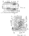
- the supporting structure 2 may be a saddle-shaped member, the screw stem 5 with external threads along its length is slidably supported in the supporting holes 9, 20 bored in the two arms of the saddle (supporting arms). Guiding surfaces 32, 35 are provided on the left supporting arm (Fig. 5) to slidably engage with the guiding surfaces 33, 34 on the partially threaded nut 3 to guide the lift of the latter.
- the lift-guiding members may be guided kinematic pairs with gliding members or rollers; the cross-section of the guiding members may be of various shapes such as rectangular, triangular, dove-tail shaped or curvilinear (circular or arc-shaped).
- the lift-guiding surfaces 72, 74 may be machined off the inner face of the side bars 82, 75 (see Figs. 11, 12).
- the side bars 82, 75 may be separate members of the main framework and fixed to the latter after machining and assembled with a fixing piece 83 (Fig. 14).
- the supporting surface 15 in the base plate of the structure contacts the outer periphery 26 of the nut-lifting sleeve 4, while the bottom face of the base plate is secured to the vice body by screws 18.
- the joining method of the supporting structure with the vice body or sliding table may also use any other surface of the structure to join with a fixed (or movable) vice member (or sliding table), the supporting structure may even be integrally incorporated in the fixed (or movable) member 13 of the vice, as is shown in Fig. 10. Also, the aims with the supporting holes may be separately fixed onto the sliding table away from the structure.
- the "partially threaded nut” 3 has an oval bore composed of two semi-circular holes and a connecting central portion.
- the lower (or upper) semi-circular hole has internal thread 16 (preferably Acme thread or sharp V thread) to mesh with the external thread on the screw stem 5, the threaded portion extends over slightly less then half of the perimeter of the hole, the upper (or lower) semi-circular hole 24 has a plain internal surface, with an internal diameter larger than the external diameter of the screw stem. The distance between the centers of the two semi-circular holes is greater than the tooth height of the thread.
- the partially threaded nut 3 may have the form of a half-nut, deleting its upper, plan-surfaced half.
- two guiding surfaces 33 and 34 are provided in a recess (or it may also be designed as male guiding surfaces, such as 77, 81 in Fig. 12) to Slidably engage with the guiding surfaces 32, 35 (or guiding surfaces 74, 72 in Fig. 12) in the supporting structure.
- two diametrically opposite corners 23, 27 are in contact engagement with the depressing and lifting cam surfaces 22, 25 disposed on the inner periphery of the nut-lifting sleeve 4. Said corners may be rounded off to have arc surfaces of a small radius.
- the nut-lifting device with an overload release mechanism consists of a nut-lifting sleeve 4, a pawl 6, a looped coil spring 7 and a stop pin 12.
- the two cam surfaces 25, 22 to effect the rise and fall of the nut 3 are provided on the inner surface at the left end of the nut-lifting sleeve 4, said cam surfaces 25, 22 are in contact engagement with the corresponding corners 27, 23 on the partially threaded nut 3.
- a looped coil spring 60 (or the strip spring 100 in Fig. 17) to replace the function of cam surface 22 to force the partially threaded nut 3 to descend.
- alternative devices may be used to effect the up and down movement of the nut 3, for instance, co-functioning end-face cams, or end-face cam-groove and guide-pin may be set in the end face 55 of the partially threaded nut 3 and the end face 56 of the nut-lifting sleeve 4 (Fig. 6) to replace the cam surfaces 22, 25.
- Other equivalent-effect devices such as connecting rods, cranks and levers may also be used.
- the bore 10 at the right end of the nut-lifting sleeve 4 fits slidably over the outer periphery of the screw stem 5, and the outer periphery 26 concentric with are 10 is in contact with the supporting surface 15.
- a hole 8 is located at the right end of the nut-lifting sleeve 4, wherein a pawl 6 is slidably encased.
- one (or more) groove 14 is provided around the outer periphery of the nut-lifting sleeve 4, wherein a looped coil spring 7 is placed to press on the pawl 6, so that the slant face 37 at the lower tip of the pawl 6 is tightly pressed in the axial keyway 28 and engages with the lateral edge of said keyway 28.
- the screw stem 5 continues to be turned in the direction M, the force acting on the slant face 37 of the pawl 6 increases, until the axial component of the force acting on the pawl 6 overcomes the tightening force of the looped coil spring 7 and the slant face 37 slips out of the keyway 28, causing the disengagement of the nut-lifting sleeve 4 from the screw stem 5 while not impeding the further turning of the screw stem 5, playing the role of an overload releasing clutch.
- the lower tip of the pawl 6 may be more appropriately designed to have two opposite slant faces, thus would serve as a bi-directional overload clutch.
- a bench vice is taken as the embodiment example here, when the screw stem 5 is turned in the opposite direction (i.e.
- overload clutches In the process of torque-transmission from the screw stem 5 to the nut-lifting sleeve 4, various forms of overload clutches with equivalent effects may be used. Classifying them by their types, they may be uni-directional, bi-directional, over-riding, magnetic, hydraulic or pneumatic; classifying them by their clutching elements, they may have pawls, jaws, steel balls, guide pins, friction cones (discs, plates, blocks, rings, pads, etc.) and various springy elements (such as springs, expanding rings, contracting hoops, expanding sleeves, etc.).
- all types of overload clutches are the equivalents of the overload release devices within the scope of the present invention. Some embodiment examples of the overload release devices are described below. Figs.
- the friction ring (cone) 61 is disposed within the nut-lifting sleeve 4 and is slidably mounted on the periphery of the screw stem 5. Under the action of the compression spring 63, its left friction surface (cone) 67 is tightly pressed against the right friction surface (cone) 68 of the nut-lifting sleeve 4. The friction ring (cone) 61 is connected with the screw stem 5 through the guide key 62.
- Fig. 15 shows an expanding friction ring type overload release device. Its working principle is: the friction ring 61 and compression spring 63 in Fig. 11 are replaced by the expanding friction ring 86, and the limiting ring 64 is used in this case to limit the axial movement of the expanding friction ring 86.
- An open slot 91 is made in the cylindrical body of the ring 86. In its free state this ring will have a diameter of its external periphery 87 larger than the diameter of the bore 88 of the nut-lifting sleeve 4. When assembling, the open slot 91 is forced to close, releasing it after the ring 86 has been slipped into the bore 88.
- the external periphery 87 of the expanding ring 86 will bear against the bore surface 88 under its own spring force, producing a frictional force between them.
- the internal diameter of the expanding ring 86 is slightly larger than the external diameter of the screw stem 5, the expanding ring being connected with the screw stem 5 through the guide key 90.
- the working process is similar to that of the friction ring in Fig. 11, the difference being during overload condition slipping occurs at the external periphery of the expanding ring instead of the end surface of the friction ring.
- Fig. 16 shows a contracting friction hoop type overload release device. Its working principle is substantially similar to that of the device shown in Fig. 15.
- the contracting friction hoop 92 also has an axial open slot 94. In its free state the internal diameter of its bore 95 is slightly smaller than the external diameter 96 of the screw stem 5. After assembling, the hoop 92 will tightly hold on the cylindrical periphery of the screw stem 5, producing a frictional force between them. (There is no keyway on the screw stem 5 in this case).
- the external diameter of the contracting friction hoop 92 is smaller than that of the bore of the nut-lifting sleeve 4.
- the turning torque of the screw stem 5 is transmitted to the nut-lifting sleeve through a pin 93. Its working process is similar to that of the device shown in Fig. 15, only the slipping under overload condition takes place between the friction surfaces of the external periphery of screw stem 5 and the inner surface of the bore of the hoop.
- Fig. 17 is an axially disposed guide pin (or steel ball) overload release device. Its working principle is thus: in the left end surface of the sleeve 102 mounted on the screw stem 5 is drilled an axial hole, wherein a small compression spring 103 and a guide pin (or steel ball) 104 is lodged. This pin (or steel ball) engages with a small conical dent 105 located in the right end surface of the nut-lifting sleeve 4. Also its working process is basically similar to that of the device in Fig. 11, only the friction of the end surfaces in Fig. 11 is substituted by the clogging force between the conical dent and guide pin (or steel ball).
- the device shown in Fig. 18 is an equivalent of that in Fig. 17, only that the axially disposed guide pin hole in Fig. 17 is replaced by the radially guide pin hole in Fig. 18. Their working principles are the same.
- a motion-limiting slot 11 to limit the turning angle of the nut-lifting sleeve 4 through the contact of the stop pin 12 with the two extremities 30, 36 of the slot.
- the motion-limiting slot 11 may be replaced by a slot over an arc in the periphery at the right end of the nut-lifting sleeve 4 or by a circumferential slot over an arc, or the stop pin 12 (one or two) may be fixed on the outer periphery of the nut-lifting sleeve 4, as is shown in Fig.
- the limiting faces 38, 39 on the two sides of the base plate can be used to limit the turning angle of the nut-lifting sleeve 4.
- the support is designed in the form of a framework as is shown in Figs. 11, 12, the surface underneath the side bars 79, 76 may be used as limiting faces. Obviously there may be numerous motion-limiting devices that fall within the scope of the present invention.
- One or more axial slots are disposed on the outer periphery of the screw stem 5. These slots are to engage with the pawl 6 in Fig. 2, and to co-function with the guide key in Figs. 11, 15, 17. When adopting the overload release device of the contracting-hoop type shown in Fig. 16, no slots need to be provided on screw stem 5.
- the lateral face of the keyway 28 bears against the right-angled face 29 of the pawl 6 and drives the nut-lifting sleeve 4 to turn left, whereby the cam surface 22 acts on the upper corner 23 of the nut and depresses the latter until stop pin 12 engages with the left extremity 30 of the arc-shaped slot 11.
- the center line of the internal threads in the partially threaded nut 3 is lowered from its highest position 01-01 to its lowest position 02-02, completely disengaging the internal thread 16 in the nut from the external thread on the screw stem 5.
- the screw stem 5 and the movable vice member 1 can now be pulled back freely with the hand, fulfilling the requirement of fast traversing over the empty-travel and quick adjustment of the opening of the gap between the vice jaws.
- the handle 21 is operated to cause the screw stem 5 to turn towards the right, in the direction M (see Figs. 6, 7, 8), the lateral edge of the keyway 28 bears against the slant face 37 of the pawl 6 and drives the nut-lifting sleeve 4 to turn right, whereby the cam surface 25 acts on the lower corner 27 of the nut 3 and lifts the latter until stop pin 12 engages with the right extremity 36 of the arc-shaped slot 11.
- Fig. 11 shows a lift-nut-to-engage type screw-and-nut mechanism with a framework wherein is disposed a nut-lifting sleeve having only a lower cam surface and an end-friction-ring type overload release device. Its working principle is basically the same as that in Fig. 2.
- the screw stem 5 is turned in the direction M, the torque in the screw stem is transmitted to the nut-lifting sleeve 4 through the guide key 62 and the friction ring 61, causing the nut-lifting sleeve 4 to turn also in the direction M, until it is stopped by the limiting face 79.
- Fig. 19 shows the inclusion of a locking mechanism that may be used to control the lifting and depressing of the partially threaded nut, thus enabling the screw stem 5 not only to advance slowly but also retract slowly.
- the locking mechanism comprises of a set pin 46, a compression spring 45, a tapered-tip screw 47 and a locating face 41 in the nut-lifting sleeve 4.
- the set pin 46 is received in the stepped guide holes 52 and 51.
- the set pin 46 is raised or lowered.
- its top face 42 will abut against the locating face 41 in the nut-lifting sleeve 4, the spring 45 is compressed.
- the screw 47 is turned to be retracted towards the left, the tapered tip at its right end will be retracted towards the left, the tapered tip 50 of the set pin will be lowered under the action of the spring 45, the top face 42 of the set pin 46 is also lowered, until it is clear of the outer periphery 26 of the nut-lifting sleeve 4 and no longer hinders its rotation.
- locking mechanism may be made to lock the partially threaded nut directly, the only thing one has to do is to make the top face 42 of the set pin 46 to abut against a certain part of the partially threaded nut 3.
- locking mechanism itself, there may also be many options with equivalent effects and operating methods, such as to use a connecting-bar mechanism and the like for remote operation or remote control, to use hydraulic, pneumatic or magnetic actuators for raising or lowering the set pin 46. All these fall within the scope of the present invention.
- the supporting structure in Fig. 2 may dispense with the right supporting arm and its supporting hole 9 and retain only the left supporting arm with the supporting hole 20;
- a guide sleeve made of comparatively hard material may be fixed in the supporting hole, or the guide sleeve may also be integrally incorporated in the right end of the nut-lifting sleeve 4.
Landscapes
- Engineering & Computer Science (AREA)
- Mechanical Engineering (AREA)
- General Engineering & Computer Science (AREA)
- One-Way And Automatic Clutches, And Combinations Of Different Clutches (AREA)
- Transmission Devices (AREA)
Applications Claiming Priority (2)
| Application Number | Priority Date | Filing Date | Title |
|---|---|---|---|
| CN 91101816 CN1024037C (zh) | 1991-04-03 | 1991-04-03 | 三点包容螺母升降自动同步开合式螺杆机构 |
| CN91101816 | 1991-04-03 |
Publications (2)
| Publication Number | Publication Date |
|---|---|
| EP0508569A1 true EP0508569A1 (fr) | 1992-10-14 |
| EP0508569B1 EP0508569B1 (fr) | 1996-09-18 |
Family
ID=4905275
Family Applications (1)
| Application Number | Title | Priority Date | Filing Date |
|---|---|---|---|
| EP19920301117 Expired - Lifetime EP0508569B1 (fr) | 1991-04-03 | 1992-02-11 | Mécanisme vis-écron à accouplement synchronique |
Country Status (3)
| Country | Link |
|---|---|
| EP (1) | EP0508569B1 (fr) |
| CN (1) | CN1024037C (fr) |
| DE (1) | DE69213801D1 (fr) |
Cited By (4)
| Publication number | Priority date | Publication date | Assignee | Title |
|---|---|---|---|---|
| FR2704292A1 (fr) * | 1993-04-23 | 1994-10-28 | Fan Chaolai | Mécanisme d'entraînement à vis à vitesses élevée et faible. |
| AU704054B2 (en) * | 1994-08-18 | 1999-04-15 | Chaolai Fan | Quickly movable elastically engaging screw-and-nut mechanism |
| WO2006108197A1 (fr) * | 2005-04-11 | 2006-10-19 | Grigoryan, Emil | Roue spirale |
| CN116336153A (zh) * | 2023-02-17 | 2023-06-27 | 西南大学 | 一种丝杠传动端部自动离合装置 |
Families Citing this family (7)
| Publication number | Priority date | Publication date | Assignee | Title |
|---|---|---|---|---|
| CN1044029C (zh) * | 1994-08-18 | 1999-07-07 | 范朝来 | 柔性自动啮合快速调距式螺杆机构 |
| CN104033494A (zh) * | 2014-06-06 | 2014-09-10 | 嘉善天慧光电科技有限公司 | 滑动台锁紧装置 |
| CN104627860B (zh) * | 2015-02-12 | 2016-05-11 | 合肥工业大学(马鞍山)高新技术研究院 | 一种便于拆卸升降螺母的平衡吊 |
| CN108594069A (zh) * | 2018-04-08 | 2018-09-28 | 苏州银蕨电力科技有限公司 | 一种改进的智能电网传感装置 |
| CN110977499A (zh) * | 2019-11-20 | 2020-04-10 | 江苏昊雄智能装备有限公司 | 一种数控龙门加工中心横梁导轨结构 |
| US11660728B2 (en) | 2021-08-09 | 2023-05-30 | Snap-On Incorporated | Modular vise |
| CN121798914A (zh) * | 2026-03-11 | 2026-04-07 | 泉州市华瀚箱包股份有限公司 | 一种背包生产用的材料复合热压设备 |
Citations (6)
| Publication number | Priority date | Publication date | Assignee | Title |
|---|---|---|---|---|
| GB819506A (en) * | 1957-01-11 | 1959-09-02 | Wilton Tool Mfg Co Inc | Clamping and holding device |
| US3007358A (en) * | 1959-08-13 | 1961-11-07 | Wilton Tool Mfg Co Inc | Universal turret vises |
| US3492886A (en) * | 1967-10-25 | 1970-02-03 | Wilton Corp | Quick acting screw-threaded device |
| DE2814137A1 (de) * | 1978-04-01 | 1979-10-11 | Karl Geisel | Selbsttaetige vorschubausloesung vorwiegend fuer leitspindeldrehmaschinen |
| EP0354644A2 (fr) * | 1988-08-08 | 1990-02-14 | Chaolai Fan | Mécanisme de vissage et étau |
| CN1046213A (zh) * | 1989-04-07 | 1990-10-17 | 范朝来 | 新型螺杆传动机构 |
-
1991
- 1991-04-03 CN CN 91101816 patent/CN1024037C/zh not_active Expired - Fee Related
-
1992
- 1992-02-11 DE DE69213801T patent/DE69213801D1/de not_active Expired - Lifetime
- 1992-02-11 EP EP19920301117 patent/EP0508569B1/fr not_active Expired - Lifetime
Patent Citations (6)
| Publication number | Priority date | Publication date | Assignee | Title |
|---|---|---|---|---|
| GB819506A (en) * | 1957-01-11 | 1959-09-02 | Wilton Tool Mfg Co Inc | Clamping and holding device |
| US3007358A (en) * | 1959-08-13 | 1961-11-07 | Wilton Tool Mfg Co Inc | Universal turret vises |
| US3492886A (en) * | 1967-10-25 | 1970-02-03 | Wilton Corp | Quick acting screw-threaded device |
| DE2814137A1 (de) * | 1978-04-01 | 1979-10-11 | Karl Geisel | Selbsttaetige vorschubausloesung vorwiegend fuer leitspindeldrehmaschinen |
| EP0354644A2 (fr) * | 1988-08-08 | 1990-02-14 | Chaolai Fan | Mécanisme de vissage et étau |
| CN1046213A (zh) * | 1989-04-07 | 1990-10-17 | 范朝来 | 新型螺杆传动机构 |
Cited By (4)
| Publication number | Priority date | Publication date | Assignee | Title |
|---|---|---|---|---|
| FR2704292A1 (fr) * | 1993-04-23 | 1994-10-28 | Fan Chaolai | Mécanisme d'entraînement à vis à vitesses élevée et faible. |
| AU704054B2 (en) * | 1994-08-18 | 1999-04-15 | Chaolai Fan | Quickly movable elastically engaging screw-and-nut mechanism |
| WO2006108197A1 (fr) * | 2005-04-11 | 2006-10-19 | Grigoryan, Emil | Roue spirale |
| CN116336153A (zh) * | 2023-02-17 | 2023-06-27 | 西南大学 | 一种丝杠传动端部自动离合装置 |
Also Published As
| Publication number | Publication date |
|---|---|
| EP0508569B1 (fr) | 1996-09-18 |
| CN1065514A (zh) | 1992-10-21 |
| DE69213801D1 (de) | 1996-10-24 |
| CN1024037C (zh) | 1994-03-16 |
Similar Documents
| Publication | Publication Date | Title |
|---|---|---|
| US5282392A (en) | Synchro-clutching screw-and-nut mechanism | |
| EP0508569B1 (fr) | Mécanisme vis-écron à accouplement synchronique | |
| EP0354644B1 (fr) | Mécanisme de vissage et étau | |
| US5970812A (en) | Quickly movable elastically engaging screw-and-nut mechanism | |
| US5351943A (en) | Multiple vice for clamping at least two workpieces | |
| US3844028A (en) | Automatic tool changer | |
| KR960007588B1 (ko) | 동력구동식 나사절삭기의 2단 변속장치 | |
| CN110683472A (zh) | 一种具有自锁功能的绞盘动力转换装置 | |
| EP0290896A2 (fr) | Mandrin, en particulier pour machine-outil | |
| US3325837A (en) | Screw thread cutting apparatus with yieldable clutch drive means | |
| US4923185A (en) | Vertical-lift screw drive mechanism | |
| US5425606A (en) | Tool clamping and releasing device | |
| CN110170930A (zh) | 能高效定位和夹紧工件的台虎钳 | |
| CN117260140B (zh) | 一种传动轴摩擦焊快换卡盘 | |
| JPH07171729A (ja) | 急緩速スクリュー駆動装置 | |
| EP0306119A2 (fr) | Dispositif d'ajustement de la position contrôlé par un programme | |
| US2040601A (en) | Chuck | |
| CN102825489A (zh) | 滑套式铣头自动锁紧机构 | |
| CN223029077U (zh) | 一种零件辅助加工机构 | |
| US4602797A (en) | Tandem chuck | |
| CN222857772U (zh) | 一种精锻滑动啮合套齿型定位夹具 | |
| CN209935918U (zh) | 升降座与立柱的滚动结构以及钻机支架 | |
| JPH0410997Y2 (fr) | ||
| CN209970684U (zh) | 升降座与立柱的驱动结构以及钻机支架 | |
| CN111716118B (zh) | 一种方便对环形零件进行固定的工装夹具 |
Legal Events
| Date | Code | Title | Description |
|---|---|---|---|
| PUAI | Public reference made under article 153(3) epc to a published international application that has entered the european phase |
Free format text: ORIGINAL CODE: 0009012 |
|
| AK | Designated contracting states |
Kind code of ref document: A1 Designated state(s): DE GB |
|
| 17P | Request for examination filed |
Effective date: 19930413 |
|
| 17Q | First examination report despatched |
Effective date: 19950102 |
|
| GRAH | Despatch of communication of intention to grant a patent |
Free format text: ORIGINAL CODE: EPIDOS IGRA |
|
| GRAA | (expected) grant |
Free format text: ORIGINAL CODE: 0009210 |
|
| GRAH | Despatch of communication of intention to grant a patent |
Free format text: ORIGINAL CODE: EPIDOS IGRA |
|
| AK | Designated contracting states |
Kind code of ref document: B1 Designated state(s): DE GB |
|
| REF | Corresponds to: |
Ref document number: 69213801 Country of ref document: DE Date of ref document: 19961024 |
|
| PG25 | Lapsed in a contracting state [announced via postgrant information from national office to epo] |
Ref country code: DE Effective date: 19961219 |
|
| PLBE | No opposition filed within time limit |
Free format text: ORIGINAL CODE: 0009261 |
|
| 26N | No opposition filed | ||
| PGFP | Annual fee paid to national office [announced via postgrant information from national office to epo] |
Ref country code: GB Payment date: 20010214 Year of fee payment: 10 |
|
| REG | Reference to a national code |
Ref country code: GB Ref legal event code: IF02 |
|
| PG25 | Lapsed in a contracting state [announced via postgrant information from national office to epo] |
Ref country code: GB Free format text: LAPSE BECAUSE OF NON-PAYMENT OF DUE FEES Effective date: 20020211 |
|
| GBPC | Gb: european patent ceased through non-payment of renewal fee |
Effective date: 20020211 |