EP0508747A2 - Abflussreinigerausgabeeinrichtung mit Verriegelungselement - Google Patents
Abflussreinigerausgabeeinrichtung mit Verriegelungselement Download PDFInfo
- Publication number
- EP0508747A2 EP0508747A2 EP92303109A EP92303109A EP0508747A2 EP 0508747 A2 EP0508747 A2 EP 0508747A2 EP 92303109 A EP92303109 A EP 92303109A EP 92303109 A EP92303109 A EP 92303109A EP 0508747 A2 EP0508747 A2 EP 0508747A2
- Authority
- EP
- European Patent Office
- Prior art keywords
- container
- dispenser
- sleeve
- drain
- end wall
- Prior art date
- Legal status (The legal status is an assumption and is not a legal conclusion. Google has not performed a legal analysis and makes no representation as to the accuracy of the status listed.)
- Granted
Links
- 230000007246 mechanism Effects 0.000 claims abstract description 8
- 238000000034 method Methods 0.000 claims abstract description 7
- 238000004140 cleaning Methods 0.000 claims abstract description 4
- 239000000463 material Substances 0.000 claims description 17
- 230000005484 gravity Effects 0.000 claims description 11
- XLYOFNOQVPJJNP-UHFFFAOYSA-N water Substances O XLYOFNOQVPJJNP-UHFFFAOYSA-N 0.000 claims description 3
- 239000007787 solid Substances 0.000 description 3
- PPBRXRYQALVLMV-UHFFFAOYSA-N Styrene Chemical compound C=CC1=CC=CC=C1 PPBRXRYQALVLMV-UHFFFAOYSA-N 0.000 description 2
- 238000007796 conventional method Methods 0.000 description 2
- -1 polyethylene Polymers 0.000 description 2
- 229920001169 thermoplastic Polymers 0.000 description 2
- 239000004416 thermosoftening plastic Substances 0.000 description 2
- 239000004698 Polyethylene Substances 0.000 description 1
- 239000004743 Polypropylene Substances 0.000 description 1
- 230000000295 complement effect Effects 0.000 description 1
- 229920001684 low density polyethylene Polymers 0.000 description 1
- 239000004702 low-density polyethylene Substances 0.000 description 1
- 238000012986 modification Methods 0.000 description 1
- 230000004048 modification Effects 0.000 description 1
- 238000000465 moulding Methods 0.000 description 1
- 239000004033 plastic Substances 0.000 description 1
- 229920003023 plastic Polymers 0.000 description 1
- 229920000573 polyethylene Polymers 0.000 description 1
- 229920001155 polypropylene Polymers 0.000 description 1
- 230000008569 process Effects 0.000 description 1
- 239000000126 substance Substances 0.000 description 1
- 230000007704 transition Effects 0.000 description 1
- 239000002699 waste material Substances 0.000 description 1
Images


Classifications
-
- B—PERFORMING OPERATIONS; TRANSPORTING
- B67—OPENING, CLOSING OR CLEANING BOTTLES, JARS OR SIMILAR CONTAINERS; LIQUID HANDLING
- B67B—APPLYING CLOSURE MEMBERS TO BOTTLES JARS, OR SIMILAR CONTAINERS; OPENING CLOSED CONTAINERS
- B67B7/00—Hand- or power-operated devices for opening closed containers
- B67B7/24—Hole-piercing devices
- B67B7/26—Hole-piercing devices combined with spouts
- B67B7/28—Hole-piercing devices combined with spouts and associated with receptacle hodlers
-
- B—PERFORMING OPERATIONS; TRANSPORTING
- B65—CONVEYING; PACKING; STORING; HANDLING THIN OR FILAMENTARY MATERIAL
- B65D—CONTAINERS FOR STORAGE OR TRANSPORT OF ARTICLES OR MATERIALS, e.g. BAGS, BARRELS, BOTTLES, BOXES, CANS, CARTONS, CRATES, DRUMS, JARS, TANKS, HOPPERS, FORWARDING CONTAINERS; ACCESSORIES, CLOSURES, OR FITTINGS THEREFOR; PACKAGING ELEMENTS; PACKAGES
- B65D47/00—Closures with filling and discharging, or with discharging, devices
- B65D47/36—Closures with frangible parts adapted to be pierced, torn or removed, to provide discharge openings
- B65D47/38—Closures with frangible parts adapted to be pierced, torn or removed, to provide discharge openings with piercing means arranged to act subsequently as a valve to control the opening
Definitions
- the present invention relates to a system for dispensing material, such as powdered drain cleaner, to a desired location, such as a drain.
- Powdered or granulated drain cleaner is conventionally packed in a bulk container. To clean a drain, a consumer must remove a cover from the container and them pour the cleaner into the drain. A spoon is often used to measure and handle the drain cleaner. This conventional method of cleaning a drain is inconvenient and messy and precautions must be taken to prevent the corrosive drain cleaner from getting on the consumer's skin.
- the conventional method may also be imprecise. Drain cleaner is wasted when too much is used at one time. And when not enough drain cleaner is used, the drain remains clogged. This is also wasteful, since another application of drain cleaner must then be used.
- a substance such as powdered drain cleaner can be neatly, conveniently, and safely handled, and can be packaged in measured doses to reduce waste.
- the present invention relates to a method of cleaning a drain, including the steps of: (A) supporting a dispenser in the vicinity of the drain; (B) while supporting the dispenser in the vicinity of the drain, opening a container within the dispenser by pushing downwardly on the container; (C) dispensing drain cleaner by gravity from the container, through the dispenser, and into the drain; and (D) reacting the drain cleaner with water within the drain.
- step (A) Prior to step (A), the container is unlocked relative to the dispenser.
- the invention in another aspect, relates to a dispenser, including: (A) a sleeve for slidably receiving a container of material to be dispensed; (B) a funnel for conveying the material from the container by gravity, the funnel being axially aligned with and integrally connected to the sleeve; (C) a chute for conveying the material from the funnel by gravity to a desired location, the chute being integrally connected to the funnel and angled with respect to the central axis of the sleeve; (D) a base for supporting the dispenser, the base being in the vicinity of the chute; and (E) a pin for opening the container by rotating an end wall of the container, the pin being integrally connected to the funnel, extending upwardly within the sleeve, and being parallel to but off-center with respect to the axis of the sleeve.
- the dispenser includes means for locking the container and sleeve in respective positions which prevent use of the dispenser.
- the invention also relates to a dispensing system which includes a container with an angled end wall and a dispenser for selectively storing the container and cutting the end wall to open the container.
- the invention also relates to a container with a movable stem for opening a bottom end wall, and a plug with an open portion for receiving the top end of the stem and an actuating portion for pushing the stem downwardly.
- the invention also relates to a dispenser with a pin for opening a container by separating a lower end wall from a side wall of the container.
- the pin has a point for piercing the lower end wall and a ledge for pushing upwardly on the lower end wall.
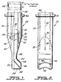
- Fig. 1 a dispenser constructed in accordance with the principles of the present invention and designated generally as 20.
- the dispenser 20 includes a ribbed sleeve 22 for receiving a container or canister 24 containing a desired amount of drain cleaner.
- the sleeve 22 has a cylindrical side wall 26 which defines an open top 28, an open bottom 30, and a central axis 32.
- a funnel 34 for conveying the drain cleaner by gravity from the sleeve 22 is axially aligned with the central axis 32.
- the funnel 34 has an open circular top 36 which is integral with the bottom 30 of the sleeve 22.
- the funnel 34 tapers downwardly to an open bottom 38.
- the funnel 34 has flat sides 40, 42 which make a transition from the circular cross-section of the cylindrical sleeve 22 to a rectangular cross-section at the bottom 38.
- a chute 44 for conveying the drain cleaner into a drain is integrally connected to the rectangular bottom 38 of the funnel 34.
- the chute 44 makes a 45° angle with the axis 32.
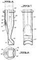
- the end 46 of the chute 44 has a rectangular cross-section with cutout C-shaped sections 48, 50 (Fig. 2) so as to conform to the circular edge of the drain.
- a base 52 (Fig. 1) for supporting the dispenser 20 in the vicinity of the drain is located directly beneath the angled chute 44.
- the base 52 is solid and extends downwardly to a bottom surface 54 which is even with the bottom of the chute 44.
- the chute is only as wide as the bottom of the funnel.
- the canister 24 has a cylindrical side wall 56 which slidably matches the ribbed cylindrical side wall 26 of the sleeve 22.
- the bottom of the canister 24 is closed by a disk 58 which rests on edges 60 which are turned inwardly from the side wall 56.
- a plug 62 closes the top of the canister 24.
- the canister 24 is preferably a spiral wound canister and can be formed of many suitable materials.
- a pin 64 (Fig. 1) for opening the canister 24 extends upwardly from the flat side 40 of the funnel 34.
- the pin 64 is parallel to but off-center with respect to the axis 32 and extends through the open bottom 30 and partially into the sleeve 22.
- the dispenser 20 is preferably supported by placing the bottom surface 54 on the surface of a sink surrounding a drain with the C-shaped section 50 matching the circular edge of the drain.
- the canister 24 is then pushed downwardly into the sleeve 22. This causes the pin 64 to rotate the disk 58 into an open position (illustrated in dotted lines in Fig. 1).
- the powdered drain cleaner then falls by gravity from the opened canister 24, through the funnel 34 and the chute 44, and into the drain. Within the drain, the powdered drain cleaner reacts with water to release heat to clean the drain.
- a gripping shoulder 66 for gripping the dispenser 20 during use is integrally connected to the sleeve 22, near the open top 28.
- the shoulder 66 surrounds the entire periphery of the sleeve 22.
- FIGs. 6-10 A second embodiment of the invention is illustrated in Figs. 6-10.
- the second embodiment and the first embodiment have many features in common. These features are indicated by the same reference numerals in the drawings so that their description need not be repeated.
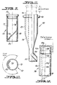
- the second embodiment includes a dispenser 68 (Figs. 6-8) which is adapted to store and open a canister 70 (Figs. 9 and 10).
- the canister 70 includes a cylindrical side wall 72, an angled bottom wall 74, and a plug 76.
- the bottom wall 74 preferably forms a 45° angle with respect to the axis 78 of the side wall 72 and is frangibly connected to the side wall 72 along at least a portion of its periphery.
- a C-shaped direction tab 80 is located in the vicinity of the frangible connection between the side wall 72 and the bottom wall 74.
- the dispenser 68 includes a cutter 82 which extends upwardly from a side 42 of the funnel 34.
- the cutter 82 has a point 84 which is C-shaped (viewed along the main axis 32 of the dispenser 68).
- the cutter 82 is located on only one side of the dispenser 68 so that the canister 70 can fit within the sleeve 22 for storage without opening its lower end wall 74. That is, the canister 70 can be located within the sleeve 22 with the direction tab 80 on the side wall of the dispenser 68 opposite from the cutter 82 and with the point 84 (Fig. 6) fitting within an upper corner 86 (Fig. 9).
- the canister 70 is lifted and then rotated through 180° such that the direction tab 80 is directly above the cutter 82.
- the canister 70 is then pushed downwardly such that the point 84 pierces the frangible connection between the bottom wall 74 and the side wall 72 of the canister 70.
- the cutter 82 continues on up within the canister 70 such that a C-shaped lower portion of the side wall 72 fits within an annular space 88 between the cutter 82 and the cylindrical sides 26 of the sleeve 22.
- the direction tab 80 ensures that the bottom wall 74 is torn away from the side wall 72 and is not stretched into the space 88 between the cutter 82 and the sleeve 22.
- Powdered drain cleaner falls by gravity from the opened canister 70 through passageways 90 (Fig. 8) molded into the cutter 82.
- the dispenser 68 otherwise operates like the dispenser 20 of Fig. 1, with the powdered drain cleaner being conveyed through the funnel 34, chute 44, and then into the drain.
- a third embodiment of the invention is illustrated in Figs. 11 and 12.
- a dispenser 92 (Fig. 11) in accordance with the third embodiment is substantially identical to the dispenser 20 except that the dispenser 92 does not have the pin 64 of the dispenser 20.
- the dispenser 92 is used to dispense powdered drain cleaner from a canister 94, illustrated in Fig. 12.
- the canister 94 is formed of plastic with a cylindrical side wall 96, a tear-away bottom 98, and a selectively orientable plug 100.
- An actuating stem 102 is integrally connected to the tear-away bottom 98 and extends almost to the other end of the canister 94.
- the stem 102 is parallel to but off-center with respect to a central axis 104 of the canister 94.
- the plug 100 has an open portion 106 for receiving the upper end 108 of the stem 102, a solid actuating portion 110, and shoulders 112 for limiting the extent to which the plug 100 can be pushed within the side wall 96.
- the upper end 108 of the stem 102 is received within the open portion 106 while the shoulders 112 engage the top edge of the side wall 96.
- the plug 100 is pulled upwardly away from the side wall 96 and then rotated through 180° such that the solid actuating portion 110 is located directly above the end 108 of the stem 102.
- the plug 100 is then pushed downwardly while gripping the shoulder of the dispenser 92. Since the canister 94 is too wide to move into the funnel 34, the stem 102 tears the bottom 98 away from the side wall 96.
- the stem 102 is preferably somewhat bendable and cooperates with the side wall 96 to facilitate the opening of the canister 94, as illustrated in dotted lines in Fig. 12. Powdered drain cleaner then falls from the opened canister 94 by gravity and is conveyed through the funnel 34, the chute 44, and into the drain, as in the first and second embodiment.
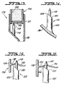
- a dispenser 114 in accordance with a fourth embodiment of the invention is illustrated in Figs. 13-18.
- the dispenser 114 has a pointed pin 116 but is otherwise identical to the dispenser 20 illustrated in Fig. 1.
- the pin 116 has a point 118 and a ledge 120.
- the pin 116 extends upwardly from the funnel 34 in a direction which is parallel to but spaced apart from the central axis of the sleeve 22.
- the pin 116 consists of a cylindrical main portion 122, the ledge 120 and the point 118.
- the ledge 120 preferably forms a 45° angle with the central axis of the main portion 122.
- the upper edge 124 of the ledge 124 is slightly rounded.
- a canister 126 for use with the dispenser 114 has a side wall 128 and a lower end wall 130.
- the periphery 132 of the lower end wall 130 is frangibly connected to the side wall 128.
- the canister 126 is molded of a low density polyethylene thermoplastic, and the lower end wall 130 is formed of a polyethylene or polypropylene slug which is molded into the bottom of the canister 126.
- the material in the canister 126 is filled through the bottom of the canister 126 and then the lower end wall 130 is molded in place.
- the lower end wall 130 is pierced by the point 118 (Fig. 15). This piercing does not by itself cause the lower end wall 130 to separate from the side wall 128.
- the rounded edge 124 of the ledge 120 abuts against a portion of the lower end wall 130. Since the edge 124 is not sharp, it pushes upwardly against and tears the lower end wall 130 away from the side wall 128 at the frangible periphery 132, as illustrated in Fig. 17.
- the lower end wall 130 is shown in its fully opened position in Fig. 18. As illustrated in Fig. 18, the point 118 remains pierced within the lower end wall 130, thereby preventing the wall 130 from falling into and clogging the funnel 34.
- Each of the dispensers described above is advantageously formed as an integral unit, i.e., in one piece.
- the dispensers may thus be easily manufactured of styrene or a suitable thermoplastic using conventional molding techniques.
- a locking mechanism for the invention is illustrated in Figs. 19, 19a and 19b in connection with the fourth embodiment.
- the locking mechanism consists of a rectangular shaped protrusion or detent 150 formed along an inner surface of sleeve 22 and a slot 160 formed in the bottom portion of the sidewall 128 of canister 126.
- the protrusion 150 extends parallel to the central axis 32 shown in Fig. 1 and is slidably received within a complementary rectangular shaped slot 160 which is oriented longitudinally along an outer surface of canister 126 (when protrusion 150 and slot 160 are aligned as shown in Figs. 19 and 19b).
- the protrusion 150 need not be axially elongated and can take other forms, for example it could be circular in shape with a diameter smaller than the width of slot 160.
- Slot 160 is also preferably parallel to the central axis 32 of dispenser 20. When protrusion 150 and slot 160 are not aligned, the lower end wall of canister 126 abuts the top of protrusion 150 preventing downward movement of canister 126 into sleeve 22. Thus, protrusion 150 and slot 160 cooperate (when not aligned) to lock dispenser 114, specifically, container 126 and sleeve 22, in a position relative to one another which prevents use of dispenser 114.
- canister 126 When a user desires to dispense drain cleaner into a drain, canister 126 is rotated clockwise or counterclockwise (as shown by the arrows in Fig. 19b) with respect to sleeve 22 until protrusion 150 and slot 160 are aligned and then canister 126 is forced downward into sleeve 22.
Landscapes
- Engineering & Computer Science (AREA)
- Mechanical Engineering (AREA)
- Containers And Packaging Bodies Having A Special Means To Remove Contents (AREA)
- Closures For Containers (AREA)
- Treatment Of Water By Ion Exchange (AREA)
- Water Treatment By Sorption (AREA)
- Sink And Installation For Waste Water (AREA)
- Filtration Of Liquid (AREA)
- Cleaning In General (AREA)
- Nozzles For Electric Vacuum Cleaners (AREA)
- Packaging Of Annular Or Rod-Shaped Articles, Wearing Apparel, Cassettes, Or The Like (AREA)
- Crystals, And After-Treatments Of Crystals (AREA)
- Manufacturing Of Electric Cables (AREA)
- Electrical Discharge Machining, Electrochemical Machining, And Combined Machining (AREA)
- Bidet-Like Cleaning Device And Other Flush Toilet Accessories (AREA)
- Crushing And Pulverization Processes (AREA)
Applications Claiming Priority (4)
| Application Number | Priority Date | Filing Date | Title |
|---|---|---|---|
| US07/681,953 US5253684A (en) | 1991-04-08 | 1991-04-08 | Drain cleaner dispenser |
| US681953 | 1991-04-08 | ||
| US824160 | 1992-01-22 | ||
| US07/824,160 US5251559A (en) | 1991-04-08 | 1992-01-22 | Drain cleaner dispenser with locking feature |
Publications (3)
| Publication Number | Publication Date |
|---|---|
| EP0508747A2 true EP0508747A2 (de) | 1992-10-14 |
| EP0508747A3 EP0508747A3 (en) | 1993-08-18 |
| EP0508747B1 EP0508747B1 (de) | 1996-12-04 |
Family
ID=27102781
Family Applications (1)
| Application Number | Title | Priority Date | Filing Date |
|---|---|---|---|
| EP92303109A Expired - Lifetime EP0508747B1 (de) | 1991-04-08 | 1992-04-08 | Abflussreinigerausgabeeinrichtung mit Verriegelungselement |
Country Status (13)
| Country | Link |
|---|---|
| US (2) | US5251559A (de) |
| EP (1) | EP0508747B1 (de) |
| JP (1) | JP2689048B2 (de) |
| KR (1) | KR0185748B1 (de) |
| AT (1) | ATE145874T1 (de) |
| AU (1) | AU646726B2 (de) |
| BR (1) | BR9201368A (de) |
| CA (1) | CA2065505C (de) |
| DE (1) | DE69215573T2 (de) |
| DK (1) | DK0508747T3 (de) |
| ES (1) | ES2096029T3 (de) |
| GR (1) | GR3022469T3 (de) |
| MX (1) | MX9201619A (de) |
Cited By (1)
| Publication number | Priority date | Publication date | Assignee | Title |
|---|---|---|---|---|
| CN107175248A (zh) * | 2017-06-14 | 2017-09-19 | 天津七盛新能源科技有限公司 | 一种废气处理装置 |
Families Citing this family (8)
| Publication number | Priority date | Publication date | Assignee | Title |
|---|---|---|---|---|
| US5253684A (en) * | 1991-04-08 | 1993-10-19 | Block Drug Company, Inc. | Drain cleaner dispenser |
| US5251559A (en) * | 1991-04-08 | 1993-10-12 | Block Drug Company, Inc. | Drain cleaner dispenser with locking feature |
| US20090293214A1 (en) * | 2007-05-09 | 2009-12-03 | Ackerman Bryan L | Drain clog remover and shaft usable therewith |
| US20080276359A1 (en) * | 2007-05-09 | 2008-11-13 | Morgan Terra J | Drain clog remover |
| US8745771B2 (en) * | 2008-12-02 | 2014-06-10 | S.C. Johnson & Sons, Inc. | Drain clog remover |
| US8739968B2 (en) * | 2008-12-02 | 2014-06-03 | S.C. Johnson & Son, Inc. | Drain clog remover |
| CN104492766A (zh) * | 2014-12-03 | 2015-04-08 | 云南农业大学 | 基于分隔处理的插入式灌水器化学抗堵法 |
| CN113023128B (zh) * | 2019-12-25 | 2022-10-18 | 常德烟草机械有限责任公司 | 一种卷烟设备及其烟丝输送装置 |
Family Cites Families (24)
| Publication number | Priority date | Publication date | Assignee | Title |
|---|---|---|---|---|
| US1657783A (en) * | 1926-06-10 | 1928-01-31 | Gustaf A Berg | Method and means for emptying milk bottles |
| GB408257A (en) * | 1932-09-30 | 1934-04-03 | Continental Can Co | Improvements in or relating to the dispensing of liquids |
| CH199746A (fr) * | 1937-08-28 | 1938-09-15 | Willy Bourquin | Appareil pour ouvrir et vider des boîtes métalliques contenant un liquide. |
| GB701809A (en) * | 1951-04-25 | 1954-01-06 | Churchill Henry Winston S | Improvements relating to apparatus for dispensing pastes, liquids and other substances |
| US2776782A (en) * | 1953-01-16 | 1957-01-08 | Gilbert & Barker Mfg Co | Air-operated can-emptying means |
| US3182858A (en) * | 1962-07-30 | 1965-05-11 | Beaudoin Jean | Perforating stopper for collapsible tubes |
| AU442655B2 (en) * | 1969-07-24 | 1973-11-16 | Consolidated Foods Corporation | Sewer and drain cleaner composition |
| US4060105A (en) * | 1975-09-11 | 1977-11-29 | Xerox Corporation | Toner loading apparatus with replenishing supply container |
| GB1561835A (en) * | 1976-02-11 | 1980-03-05 | Allen & Hanburys Ltd | Devices for dispensing medicamtens |
| US4150673A (en) * | 1977-02-03 | 1979-04-24 | Pharmachem Corporation | Coded entry system for blood bag |
| CH621985A5 (en) * | 1977-12-29 | 1981-03-13 | Ernst & Co Inh Geiger & Neuens | Portion package for drainage pipe cleaning agents |
| US4234103A (en) * | 1978-03-31 | 1980-11-18 | Baxter Travenol Laboratories, Inc. | Diagnostic reagent dispensing bottle |
| US4267945A (en) * | 1979-08-06 | 1981-05-19 | Maynard Jr Walter P | Liquid funnel and container piercing blade combination |
| US4311174A (en) * | 1980-05-05 | 1982-01-19 | Bull & Roberts, Inc. | Safety dispenser attachment for dangerous liquid additives |
| US4497351A (en) * | 1980-10-21 | 1985-02-05 | Garcia Tony P | Apparatus for filling a device with a fluid |
| US4600125A (en) * | 1983-08-15 | 1986-07-15 | Maynard Jr Walter P | Liquid funnel and pouring spout combination |
| US4614437A (en) * | 1984-11-02 | 1986-09-30 | Dougherty Brothers Company | Mixing container and adapter |
| US4970817A (en) * | 1987-04-10 | 1990-11-20 | Grover Mansfield | Vehicle remote oil fill apparatus |
| GB2208227A (en) * | 1988-08-11 | 1989-03-15 | Ici Plc | Introducing additive into a container |
| US5071035A (en) * | 1989-02-28 | 1991-12-10 | Kiplinger Dale V | System for transferring fluid from a container to a remote location |
| US4969491A (en) * | 1989-02-28 | 1990-11-13 | Nch Corporation | Acid drain opening system |
| IT1237155B (it) * | 1989-12-22 | 1993-05-24 | Serbatoio con bocchettone di collegamento | |
| US5253684A (en) * | 1991-04-08 | 1993-10-19 | Block Drug Company, Inc. | Drain cleaner dispenser |
| US5251559A (en) * | 1991-04-08 | 1993-10-12 | Block Drug Company, Inc. | Drain cleaner dispenser with locking feature |
-
1992
- 1992-01-22 US US07/824,160 patent/US5251559A/en not_active Expired - Fee Related
- 1992-04-06 AU AU14082/92A patent/AU646726B2/en not_active Ceased
- 1992-04-07 CA CA002065505A patent/CA2065505C/en not_active Expired - Fee Related
- 1992-04-07 BR BR929201368A patent/BR9201368A/pt not_active IP Right Cessation
- 1992-04-08 JP JP4114322A patent/JP2689048B2/ja not_active Expired - Lifetime
- 1992-04-08 DE DE69215573T patent/DE69215573T2/de not_active Expired - Fee Related
- 1992-04-08 MX MX9201619A patent/MX9201619A/es unknown
- 1992-04-08 AT AT92303109T patent/ATE145874T1/de not_active IP Right Cessation
- 1992-04-08 DK DK92303109.0T patent/DK0508747T3/da active
- 1992-04-08 ES ES92303109T patent/ES2096029T3/es not_active Expired - Lifetime
- 1992-04-08 KR KR1019920005862A patent/KR0185748B1/ko not_active Expired - Fee Related
- 1992-04-08 EP EP92303109A patent/EP0508747B1/de not_active Expired - Lifetime
-
1993
- 1993-08-23 US US08/110,315 patent/US5392823A/en not_active Expired - Fee Related
-
1997
- 1997-02-05 GR GR960403392T patent/GR3022469T3/el unknown
Cited By (1)
| Publication number | Priority date | Publication date | Assignee | Title |
|---|---|---|---|---|
| CN107175248A (zh) * | 2017-06-14 | 2017-09-19 | 天津七盛新能源科技有限公司 | 一种废气处理装置 |
Also Published As
| Publication number | Publication date |
|---|---|
| BR9201368A (pt) | 1992-12-01 |
| DK0508747T3 (da) | 1996-12-23 |
| US5392823A (en) | 1995-02-28 |
| AU1408292A (en) | 1992-10-15 |
| GR3022469T3 (en) | 1997-05-31 |
| AU646726B2 (en) | 1994-03-03 |
| CA2065505C (en) | 1996-11-26 |
| KR920019433A (ko) | 1992-11-19 |
| CA2065505A1 (en) | 1992-10-09 |
| KR0185748B1 (ko) | 1999-10-01 |
| ES2096029T3 (es) | 1997-03-01 |
| MX9201619A (es) | 1992-10-01 |
| JPH05309350A (ja) | 1993-11-22 |
| DE69215573D1 (de) | 1997-01-16 |
| ATE145874T1 (de) | 1996-12-15 |
| DE69215573T2 (de) | 1997-05-22 |
| US5251559A (en) | 1993-10-12 |
| EP0508747A3 (en) | 1993-08-18 |
| JP2689048B2 (ja) | 1997-12-10 |
| EP0508747B1 (de) | 1996-12-04 |
Similar Documents
| Publication | Publication Date | Title |
|---|---|---|
| US5253684A (en) | Drain cleaner dispenser | |
| RU2519892C2 (ru) | Дозирующее устройство с крышкой и черпаком | |
| US3730387A (en) | Pill dispensing device having plural cut-off trap chamber | |
| EP0130817B1 (de) | Ausgabevorrichtung für fliessfähiges partikelförmiges Material | |
| US5236022A (en) | Lid with built-in dispensing scoop | |
| US3432027A (en) | Dispensing container assembly | |
| US6250346B1 (en) | Device for maintaining separate ingredients in liquid food products | |
| US3491907A (en) | Break-away container | |
| EP0023786A1 (de) | Einteiliger Abgabeverschluss | |
| US5251559A (en) | Drain cleaner dispenser with locking feature | |
| US20040026420A1 (en) | Rotatable dispenser closure for use with a container | |
| US3221943A (en) | Container with valve operated nozzle | |
| US4836424A (en) | Container closure and dispenser for granular materials | |
| WO2006036673A1 (en) | Measuring and dispensing closure | |
| WO1999042380A1 (en) | Detachable shutting device for a plastic container | |
| EP0613833B1 (de) | Auslass-Verschluss | |
| US4227629A (en) | Detachable spout and closure | |
| EP1539589A2 (de) | Zweiteilige dosier-/abgabekappe | |
| US2851066A (en) | Dispensing closure for collapsible tubes | |
| EP0684459A1 (de) | Dosierlöffel | |
| KR200235884Y1 (ko) | 정용량 토출식 휴대용 분유통 | |
| US5074441A (en) | Liquid container closure lockable in the open position | |
| WO1997014632A1 (en) | A quantitative dispenser | |
| KR200201885Y1 (ko) | 분유량 조절이 가능한 휴대용 분유용기 | |
| US2561903A (en) | Detachable spout having means to form dispensing openings in containers |
Legal Events
| Date | Code | Title | Description |
|---|---|---|---|
| PUAI | Public reference made under article 153(3) epc to a published international application that has entered the european phase |
Free format text: ORIGINAL CODE: 0009012 |
|
| AK | Designated contracting states |
Kind code of ref document: A2 Designated state(s): AT BE CH DE DK ES FR GB GR IT LI LU MC NL PT SE |
|
| PUAL | Search report despatched |
Free format text: ORIGINAL CODE: 0009013 |
|
| AK | Designated contracting states |
Kind code of ref document: A3 Designated state(s): AT BE CH DE DK ES FR GB GR IT LI LU MC NL PT SE |
|
| 17P | Request for examination filed |
Effective date: 19940126 |
|
| 17Q | First examination report despatched |
Effective date: 19950102 |
|
| GRAG | Despatch of communication of intention to grant |
Free format text: ORIGINAL CODE: EPIDOS AGRA |
|
| GRAH | Despatch of communication of intention to grant a patent |
Free format text: ORIGINAL CODE: EPIDOS IGRA |
|
| ITF | It: translation for a ep patent filed | ||
| GRAH | Despatch of communication of intention to grant a patent |
Free format text: ORIGINAL CODE: EPIDOS IGRA |
|
| GRAA | (expected) grant |
Free format text: ORIGINAL CODE: 0009210 |
|
| AK | Designated contracting states |
Kind code of ref document: B1 Designated state(s): AT BE CH DE DK ES FR GB GR IT LI LU MC NL PT SE |
|
| REF | Corresponds to: |
Ref document number: 145874 Country of ref document: AT Date of ref document: 19961215 Kind code of ref document: T |
|
| REG | Reference to a national code |
Ref country code: CH Ref legal event code: NV Representative=s name: BUECHEL & PARTNER AG PATENTBUERO |
|
| REG | Reference to a national code |
Ref country code: DK Ref legal event code: T3 |
|
| REF | Corresponds to: |
Ref document number: 69215573 Country of ref document: DE Date of ref document: 19970116 |
|
| REG | Reference to a national code |
Ref country code: ES Ref legal event code: FG2A Ref document number: 2096029 Country of ref document: ES Kind code of ref document: T3 |
|
| ET | Fr: translation filed | ||
| REG | Reference to a national code |
Ref country code: GR Ref legal event code: FG4A Free format text: 3022469 |
|
| PLBE | No opposition filed within time limit |
Free format text: ORIGINAL CODE: 0009261 |
|
| STAA | Information on the status of an ep patent application or granted ep patent |
Free format text: STATUS: NO OPPOSITION FILED WITHIN TIME LIMIT |
|
| 26N | No opposition filed | ||
| PGFP | Annual fee paid to national office [announced via postgrant information from national office to epo] |
Ref country code: GB Payment date: 19980615 Year of fee payment: 7 |
|
| PGFP | Annual fee paid to national office [announced via postgrant information from national office to epo] |
Ref country code: GR Payment date: 19980624 Year of fee payment: 7 |
|
| PGFP | Annual fee paid to national office [announced via postgrant information from national office to epo] |
Ref country code: DE Payment date: 19980626 Year of fee payment: 7 Ref country code: AT Payment date: 19980626 Year of fee payment: 7 |
|
| PGFP | Annual fee paid to national office [announced via postgrant information from national office to epo] |
Ref country code: NL Payment date: 19980629 Year of fee payment: 7 |
|
| PGFP | Annual fee paid to national office [announced via postgrant information from national office to epo] |
Ref country code: DK Payment date: 19980630 Year of fee payment: 7 Ref country code: CH Payment date: 19980630 Year of fee payment: 7 |
|
| PGFP | Annual fee paid to national office [announced via postgrant information from national office to epo] |
Ref country code: PT Payment date: 19980702 Year of fee payment: 7 Ref country code: ES Payment date: 19980702 Year of fee payment: 7 |
|
| PGFP | Annual fee paid to national office [announced via postgrant information from national office to epo] |
Ref country code: FR Payment date: 19980703 Year of fee payment: 7 |
|
| PGFP | Annual fee paid to national office [announced via postgrant information from national office to epo] |
Ref country code: MC Payment date: 19980717 Year of fee payment: 7 |
|
| PGFP | Annual fee paid to national office [announced via postgrant information from national office to epo] |
Ref country code: BE Payment date: 19980813 Year of fee payment: 7 |
|
| PGFP | Annual fee paid to national office [announced via postgrant information from national office to epo] |
Ref country code: LU Payment date: 19980821 Year of fee payment: 7 |
|
| PGFP | Annual fee paid to national office [announced via postgrant information from national office to epo] |
Ref country code: SE Payment date: 19981008 Year of fee payment: 7 |
|
| PG25 | Lapsed in a contracting state [announced via postgrant information from national office to epo] |
Ref country code: LU Free format text: LAPSE BECAUSE OF NON-PAYMENT OF DUE FEES Effective date: 19990408 Ref country code: GB Free format text: LAPSE BECAUSE OF NON-PAYMENT OF DUE FEES Effective date: 19990408 Ref country code: AT Free format text: LAPSE BECAUSE OF NON-PAYMENT OF DUE FEES Effective date: 19990408 |
|
| PG25 | Lapsed in a contracting state [announced via postgrant information from national office to epo] |
Ref country code: SE Free format text: LAPSE BECAUSE OF NON-PAYMENT OF DUE FEES Effective date: 19990409 Ref country code: ES Free format text: LAPSE BECAUSE OF NON-PAYMENT OF DUE FEES Effective date: 19990409 |
|
| PG25 | Lapsed in a contracting state [announced via postgrant information from national office to epo] |
Ref country code: LI Free format text: LAPSE BECAUSE OF NON-PAYMENT OF DUE FEES Effective date: 19990430 Ref country code: GR Free format text: LAPSE BECAUSE OF NON-PAYMENT OF DUE FEES Effective date: 19990430 Ref country code: DK Free format text: LAPSE BECAUSE OF NON-PAYMENT OF DUE FEES Effective date: 19990430 Ref country code: CH Free format text: LAPSE BECAUSE OF NON-PAYMENT OF DUE FEES Effective date: 19990430 Ref country code: BE Free format text: LAPSE BECAUSE OF NON-PAYMENT OF DUE FEES Effective date: 19990430 |
|
| BERE | Be: lapsed |
Owner name: BLOCK DRUG CY INC. Effective date: 19990430 |
|
| PG25 | Lapsed in a contracting state [announced via postgrant information from national office to epo] |
Ref country code: PT Free format text: LAPSE BECAUSE OF NON-PAYMENT OF DUE FEES Effective date: 19991031 Ref country code: MC Free format text: LAPSE BECAUSE OF NON-PAYMENT OF DUE FEES Effective date: 19991031 |
|
| PG25 | Lapsed in a contracting state [announced via postgrant information from national office to epo] |
Ref country code: NL Free format text: LAPSE BECAUSE OF NON-PAYMENT OF DUE FEES Effective date: 19991101 |
|
| GBPC | Gb: european patent ceased through non-payment of renewal fee |
Effective date: 19990408 |
|
| REG | Reference to a national code |
Ref country code: CH Ref legal event code: PL |
|
| PG25 | Lapsed in a contracting state [announced via postgrant information from national office to epo] |
Ref country code: FR Free format text: LAPSE BECAUSE OF NON-PAYMENT OF DUE FEES Effective date: 19991231 |
|
| NLV4 | Nl: lapsed or anulled due to non-payment of the annual fee |
Effective date: 19991101 |
|
| EUG | Se: european patent has lapsed |
Ref document number: 92303109.0 |
|
| REG | Reference to a national code |
Ref country code: FR Ref legal event code: ST |
|
| PG25 | Lapsed in a contracting state [announced via postgrant information from national office to epo] |
Ref country code: DE Free format text: LAPSE BECAUSE OF NON-PAYMENT OF DUE FEES Effective date: 20000201 |
|
| REG | Reference to a national code |
Ref country code: PT Ref legal event code: MM4A Free format text: LAPSE DUE TO NON-PAYMENT OF FEES Effective date: 19991031 |
|
| REG | Reference to a national code |
Ref country code: DK Ref legal event code: EBP |
|
| REG | Reference to a national code |
Ref country code: ES Ref legal event code: FD2A Effective date: 20010503 |
|
| PG25 | Lapsed in a contracting state [announced via postgrant information from national office to epo] |
Ref country code: IT Free format text: LAPSE BECAUSE OF NON-PAYMENT OF DUE FEES;WARNING: LAPSES OF ITALIAN PATENTS WITH EFFECTIVE DATE BEFORE 2007 MAY HAVE OCCURRED AT ANY TIME BEFORE 2007. THE CORRECT EFFECTIVE DATE MAY BE DIFFERENT FROM THE ONE RECORDED. Effective date: 20050408 |