EP0509934A1 - Verfahren zur Führung eines Ausgrabungswerkzeugs für Bodenschlitzwände und Ausgrabungswerkzeug zur Durchführung des Verfahrens - Google Patents
Verfahren zur Führung eines Ausgrabungswerkzeugs für Bodenschlitzwände und Ausgrabungswerkzeug zur Durchführung des Verfahrens Download PDFInfo
- Publication number
- EP0509934A1 EP0509934A1 EP92401097A EP92401097A EP0509934A1 EP 0509934 A1 EP0509934 A1 EP 0509934A1 EP 92401097 A EP92401097 A EP 92401097A EP 92401097 A EP92401097 A EP 92401097A EP 0509934 A1 EP0509934 A1 EP 0509934A1
- Authority
- EP
- European Patent Office
- Prior art keywords
- groove
- guide means
- tool
- excavation
- trench
- Prior art date
- Legal status (The legal status is an assumption and is not a legal conclusion. Google has not performed a legal analysis and makes no representation as to the accuracy of the status listed.)
- Granted
Links
- 238000000034 method Methods 0.000 title claims abstract description 26
- 238000009412 basement excavation Methods 0.000 title claims description 70
- 238000009415 formwork Methods 0.000 claims description 29
- 239000000463 material Substances 0.000 claims description 19
- 230000009545 invasion Effects 0.000 claims description 15
- 238000005520 cutting process Methods 0.000 claims description 9
- 238000004519 manufacturing process Methods 0.000 claims description 5
- 238000004140 cleaning Methods 0.000 claims description 4
- 239000004568 cement Substances 0.000 description 5
- 238000003801 milling Methods 0.000 description 4
- 238000005553 drilling Methods 0.000 description 3
- 238000000605 extraction Methods 0.000 description 3
- 241000195940 Bryophyta Species 0.000 description 2
- XEEYBQQBJWHFJM-UHFFFAOYSA-N Iron Chemical compound [Fe] XEEYBQQBJWHFJM-UHFFFAOYSA-N 0.000 description 2
- 230000006378 damage Effects 0.000 description 2
- 239000006260 foam Substances 0.000 description 2
- 230000005484 gravity Effects 0.000 description 2
- 238000002347 injection Methods 0.000 description 2
- 239000007924 injection Substances 0.000 description 2
- 238000009434 installation Methods 0.000 description 2
- 239000002184 metal Substances 0.000 description 2
- 229910052751 metal Inorganic materials 0.000 description 2
- 235000011929 mousse Nutrition 0.000 description 2
- 229920005830 Polyurethane Foam Polymers 0.000 description 1
- 229910000831 Steel Inorganic materials 0.000 description 1
- 230000002411 adverse Effects 0.000 description 1
- 230000000903 blocking effect Effects 0.000 description 1
- 238000005266 casting Methods 0.000 description 1
- 238000006243 chemical reaction Methods 0.000 description 1
- 239000000470 constituent Substances 0.000 description 1
- 238000005516 engineering process Methods 0.000 description 1
- 235000021183 entrée Nutrition 0.000 description 1
- 239000000835 fiber Substances 0.000 description 1
- 239000012530 fluid Substances 0.000 description 1
- 239000004459 forage Substances 0.000 description 1
- 229910052742 iron Inorganic materials 0.000 description 1
- 230000033001 locomotion Effects 0.000 description 1
- 239000002245 particle Substances 0.000 description 1
- 230000035515 penetration Effects 0.000 description 1
- 229920002635 polyurethane Polymers 0.000 description 1
- 239000004814 polyurethane Substances 0.000 description 1
- 239000011496 polyurethane foam Substances 0.000 description 1
- 238000005096 rolling process Methods 0.000 description 1
- 239000002002 slurry Substances 0.000 description 1
- 239000007787 solid Substances 0.000 description 1
- 239000000243 solution Substances 0.000 description 1
- 239000010959 steel Substances 0.000 description 1
- 238000006467 substitution reaction Methods 0.000 description 1
Images


Classifications
-
- E—FIXED CONSTRUCTIONS
- E02—HYDRAULIC ENGINEERING; FOUNDATIONS; SOIL SHIFTING
- E02F—DREDGING; SOIL-SHIFTING
- E02F3/00—Dredgers; Soil-shifting machines
- E02F3/04—Dredgers; Soil-shifting machines mechanically-driven
- E02F3/18—Dredgers; Soil-shifting machines mechanically-driven with digging wheels turning round an axis, e.g. bucket-type wheels
- E02F3/22—Component parts
- E02F3/26—Safety or control devices
-
- E—FIXED CONSTRUCTIONS
- E02—HYDRAULIC ENGINEERING; FOUNDATIONS; SOIL SHIFTING
- E02D—FOUNDATIONS; EXCAVATIONS; EMBANKMENTS; UNDERGROUND OR UNDERWATER STRUCTURES
- E02D17/00—Excavations; Bordering of excavations; Making embankments
- E02D17/13—Foundation slots or slits; Implements for making these slots or slits
-
- E—FIXED CONSTRUCTIONS
- E02—HYDRAULIC ENGINEERING; FOUNDATIONS; SOIL SHIFTING
- E02F—DREDGING; SOIL-SHIFTING
- E02F3/00—Dredgers; Soil-shifting machines
- E02F3/04—Dredgers; Soil-shifting machines mechanically-driven
- E02F3/46—Dredgers; Soil-shifting machines mechanically-driven with reciprocating digging or scraping elements moved by cables or hoisting ropes ; Drives or control devices therefor
- E02F3/47—Dredgers; Soil-shifting machines mechanically-driven with reciprocating digging or scraping elements moved by cables or hoisting ropes ; Drives or control devices therefor with grab buckets
- E02F3/475—Dredgers; Soil-shifting machines mechanically-driven with reciprocating digging or scraping elements moved by cables or hoisting ropes ; Drives or control devices therefor with grab buckets for making foundation slots
Definitions
- the invention relates to a method of guiding the excavation tool used for the production of a wall molded into the ground, as well as a modified excavation tool useful for the implementation of this method.
- the walls molded into the ground are executed by alternating or successive elementary panels.
- the finished work is therefore made up of a succession of unitary panels which must be able to guarantee geometric continuity during execution.
- two channels are used independently or jointly.
- the first consists of giving to excavation tools (mechanical or hydraulic skips in the case of discontinuous excavation and extraction of spoil, or drum or chain cutters, or rotary cutters in the case of continuous excavation and extraction) a body of great slenderness and of section very close to the excavation section, so as to achieve, in conjunction with the lowering of the center of gravity, self-guidance on the excavation even during execution.
- Control and correction devices can be incorporated into the excavation tools so as to more or less effectively correct any deviation from the theoretical trajectory.
- the second consists in more or less effectively guiding the excavation tool on the previously executed panel.
- the formwork put in place at the end of the panel before concreting is extracted like a sliding formwork before the concrete has set completely.
- the vacuum thus created allows to ensure a certain guidance of the excavation tool when the next panel is executed.
- European patent No. 0 101 350 describes a specific process for extracting the end formwork by lateral formwork which also makes it possible, at the same time, to ensure effective guidance of the excavation tool.
- the guidance function of this device is subject to its simultaneous formwork, the primary object of the invention -described.
- this guiding method is basically based on the sliding of two elements one inside the other.
- its correct operation without completely avoiding the risks of jamming and permanent blocking, requires dynamic implementation, for example by reciprocating movement or threshing of the excavation tool, given the adverse conditions that constitute the medium heavily loaded with suspended solid particles from the ground, in which the whole is bathed.
- This system is therefore suitable in the case of the use of clamshell buckets as an excavation tool, but is less well suited in the case of the use of continuous excavation tools such as cutters and wall milling cutters.
- the invention aims to provide a new method for guiding the excavation tool used for the production of a wall molded in the ground which makes it possible to avoid any discontinuity between the successive panels of a wall molded in the ground, while being simple to implement.
- the guiding method of the invention is designed to avoid or overcome the difficulties caused by the invasion of the guiding means used by a hardenable material, such as concrete or cement laitance, an invasion which creates obstacles. hampering the proper functioning of said guide means. These obstacles are the cause of the practical failure of most of the sophisticated guidance systems that have been imagined in the past.
- the first means integral with the excavation tool, consists of a vertical element, of generally planar shape, such as an iron or steel plate, and the second guide means , provided in a sacrificial element secured to the end of the previously executed panel or in a temporary formwork adjoining said end, consists of a groove or groove extending vertically over the height of said element or formwork and in the vicinity of the central part of this one.
- the guide means consist of two vertical elements, of generally planar shape, spaced apart, parallel to each other, integral with the excavation tool, engaging, respectively, two grooves formed between the banks a sacrificial element secured to the end of the previously executed panel or a temporary formwork adjoining it and the surrounding land.
- the guide means used in the method of the invention make it possible to prevent the adjacent ends of two successive panels forming the diaphragm wall from diverging with respect to each other both in a direction transverse to the plane of the wall and in the very plane of the wall.
- the method of the invention is particularly suitable in the case where the excavation tool is a continuous excavator comprising drums or cutting chains rotating in opposite directions.
- the excavation tool is a continuous excavator comprising drums or cutting chains rotating in opposite directions.
- the correct control of the excavation tool can be checked by means of inclinometers and possibly proximity switches installed in the excavation machine.
- the invention also relates to an excavation tool suitable for implementing the aforementioned variant e) of the method of the invention.
- This tool of the continuous chain or wheeled excavator type, is characterized in that it comprises at least one guide means and at least one auxiliary tool fixed to said tool and can be engaged in a guide groove or groove cooperating with the guide means. of the excavation tool in order to eliminate any possible obstacles therein, said guide means being freely disengageable from said guide groove or groove over the entire length thereof.
- the auxiliary tool can be as described in variant e) and can either be arranged below the guide means fixed to the excavation tool, or act as a guide means itself.
- guide means consisting of one or two vertical elements, of generally planar shape, integral with the excavation tool , capable (s) of sliding in one or two stationary grooves
- these guide means could be reversed.
- the excavation tool could carry one or two elements forming groove (s) which can come to engage, in a sliding manner, on one or two rib (s) or rail (s) integral with the end of the previously executed panel or of a temporary formwork attached to said end and extending vertically over the height of said panel or formwork.
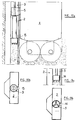
- This usually metallic formwork is provided with a vertical groove 3 extending over its entire length and in the vicinity of its central part.
- the excavation of the trench where the next panel will be molded is carried out using an excavation tool 4, such as a continuous excavation cutting machine, to which is fixed a metal plate 5 serving as a guide means .
- This plate 5 is engaged in the groove 3 at the start of the excavation operation and slides there freely from top to bottom as the tool sinks into the ground, avoiding any transverse deviation of the tool compared to the formwork.
- a force, oriented in the direction of arrow F is generated by appropriate control of the tool 4 and keeps the plate 5 engaged in the groove 4 during the excavation operation, thus avoiding any deviation. of the tool in the same plane of the trench in progress.
- FIG. 2 shows a guidance mode similar to that of FIG. 1 except that recourse is had to an excavation tool 4 which comprises two guide plates 5 arranged laterally, engaged in two grooves 3 formed between the edges of the formwork and the terrain 6 itself.
- the plates 5 of the tool guide the latter by sliding in the grooves 3.
- care is taken to generate a force F tending to press the tool against the formwork so as to maintain the plates 5 engaged in the grooves 3.
- FIGS 3 to 8 illustrate various means to prevent the invasion of the groove or grooves.
- Figures 3a and 3b show the use of filling the groove or grooves with a material 7 of low mechanical strength, for example polyurethane foam, which can be easily destroyed and subsequently eliminated. This filling is carried out before placing the formwork 2 in the ground and concreting the panel 1 so as to avoid any invasion of the groove or grooves by a hardenable material capable of forming obstacles.
- a material 7 of low mechanical strength for example polyurethane foam
- Figure 4 shows the temporary obstruction by an inflatable tube 8 of a guide groove 3 of circular cross section.
- the tube 8 is deflated and extracted from the groove before engagement of the guide plate secured to the excavation tool.
- FIG. 5 shows the use of an extractable filling element 9, such as a metal plate, to temporarily close the groove and protect it from invasion.
- This extractable element is forcibly extracted before engaging the guide plate fixed to the excavation tool in the groove.
- Figure 6 shows the use of a seal plug 10 to seal the entry of the groove and prevent its invasion. This seal plug will be destroyed before engaging the guide plate in the groove.
- FIG. 7 shows the use of a valve 11 fixed to the formwork, on one side only of the groove, to prevent the groove from flooding. This valve will be moved aside by the guide plate as it slides in the groove.
- FIG. 8 illustrates the use of an inflatable element 12 and / or of an extractable element 13 for temporarily closing lateral grooves made between a formwork and the ground (case of the embodiment of FIG. 2).
- Figures 9 to 12 illustrate various means for destroying obstacles formed in the groove or grooves in the case where they have been allowed to be invaded, in order to make them suitable for their guiding function.
- Figures 9a and 9b are elevational and plan views, respectively, showing the clearance of a circular cross-section groove invaded by hardened material, using a rotary drilling tool 14 operated from ' the surface, before the installation of the excavation tool.
- FIGS. 10a and 10b are elevation and plan views, respectively showing the clearance of a groove of circular cross section invaded by hardened material, using a percussive drilling tool 15, such as a hammer downhole type, independent of the excavation tool but working at the same time as the excavation tool so as to clear the groove as and as the excavation tool sinks into the ground.
- a percussive drilling tool 15 such as a hammer downhole type
- Figures 11a and 11b are elevation and plan views, respectively, showing the clearance of a groove provided in the central part of a formwork and invaded by a hardened material, using a cutting chain 16 , mounted on the excavation tool at a level lower than that of the guide plate, which clears the groove as the excavation tool sinks into the ground.
- the cutting chain can be driven by the same motor as that which actuates the excavation tool or by a different motor.
- Figure 12 is a plan view showing the release of lateral grooves invaded by a hardened material using two cutting chains 16, similar to that of Figures 11a and 11b, but arranged on the sides of the tool excavation.
- the two chains can be driven by a mechanism 17 driven by the same motor as that which actuates the excavation tool or by a different motor.
- chains 16 can act as first guide means so that the guide plates can be omitted.
- cutting chains could be replaced by milling wheels.
- cutting chains or milling wheels
- FIGS. 11 and 12 could be used to destroy the fillings of weak resistance material described in connection with FIGS. 3 or 8.
Landscapes
- Engineering & Computer Science (AREA)
- Mining & Mineral Resources (AREA)
- Civil Engineering (AREA)
- General Engineering & Computer Science (AREA)
- Structural Engineering (AREA)
- Mechanical Engineering (AREA)
- Life Sciences & Earth Sciences (AREA)
- General Life Sciences & Earth Sciences (AREA)
- Paleontology (AREA)
- Bulkheads Adapted To Foundation Construction (AREA)
- Earth Drilling (AREA)
- Pit Excavations, Shoring, Fill Or Stabilisation Of Slopes (AREA)
- Harvesting Machines For Root Crops (AREA)
Applications Claiming Priority (2)
| Application Number | Priority Date | Filing Date | Title |
|---|---|---|---|
| FR9104847A FR2675526A1 (fr) | 1991-04-19 | 1991-04-19 | Procede de guidage de l'outil d'excavation utilise pour la realisation d'une paroi moulee dans le sol, et outil d'excavation pour la mise en óoeuvre de ce procede. |
| FR9104847 | 1991-04-19 |
Publications (2)
| Publication Number | Publication Date |
|---|---|
| EP0509934A1 true EP0509934A1 (de) | 1992-10-21 |
| EP0509934B1 EP0509934B1 (de) | 1995-03-22 |
Family
ID=9412047
Family Applications (1)
| Application Number | Title | Priority Date | Filing Date |
|---|---|---|---|
| EP92401097A Expired - Lifetime EP0509934B1 (de) | 1991-04-19 | 1992-04-17 | Verfahren zur Führung eines Ausgrabungswerkzeugs für Bodenschlitzwände und Ausgrabungswerkzeug zur Durchführung des Verfahrens |
Country Status (11)
| Country | Link |
|---|---|
| US (1) | US5263798A (de) |
| EP (1) | EP0509934B1 (de) |
| JP (1) | JPH06316935A (de) |
| AT (1) | ATE120248T1 (de) |
| AU (1) | AU656368B2 (de) |
| CA (1) | CA2066359A1 (de) |
| DE (2) | DE69201743T2 (de) |
| ES (1) | ES2039324T1 (de) |
| FR (1) | FR2675526A1 (de) |
| GR (1) | GR930300042T1 (de) |
| TW (1) | TW216812B (de) |
Cited By (3)
| Publication number | Priority date | Publication date | Assignee | Title |
|---|---|---|---|---|
| US9371623B2 (en) | 2011-07-14 | 2016-06-21 | Ccmj Systems Ltd | Diaphragm wall apparatus and methods |
| US10988911B2 (en) | 2017-04-26 | 2021-04-27 | Ccmj Systems Ltd | Diaphragm walls |
| US11225769B2 (en) | 2018-02-15 | 2022-01-18 | Ccmj Systems Ltd | Shear key former apparatus and method(s) |
Families Citing this family (6)
| Publication number | Priority date | Publication date | Assignee | Title |
|---|---|---|---|---|
| US6503025B1 (en) * | 2000-01-11 | 2003-01-07 | Philip Glen Miller | Precast concrete beam element and methods of making and installing same |
| US6671938B2 (en) | 2000-12-27 | 2004-01-06 | United Technologies Corporation | Pneumatic press vane lift installation tool |
| US20060239782A1 (en) * | 2005-04-21 | 2006-10-26 | Hunt Arthur V | Methods and apparatuses for shaping concrete slab-on-ground foundations |
| EP2378002B1 (de) | 2010-04-16 | 2013-07-17 | BAUER Maschinen GmbH | Fräsvorrichtung zum Erstellen vertikal verlaufender Schlitze im Boden |
| IT1401736B1 (it) * | 2010-07-19 | 2013-08-02 | Soilmec Spa | Dispositivo di perforazione per l'esecuzione di diaframmi e relativo metodo. |
| FR3109163B1 (fr) * | 2020-04-14 | 2022-07-15 | Soletanche Freyssinet | Dispositif de coffrage muni d’un dispositif de mesure de déviation |
Citations (2)
| Publication number | Priority date | Publication date | Assignee | Title |
|---|---|---|---|---|
| FR2617881A1 (fr) * | 1987-07-10 | 1989-01-13 | Spie Batignolles | Procede pour realiser une paroi moulee dans le sol et coffrages destines notamment a sa mise en oeuvre |
| EP0333577A1 (de) * | 1988-03-18 | 1989-09-20 | Sondages Injections Forages "S.I.F." Entreprise Bachy | Führungssystem eines Arbeitsgerätes und Verfahren zum Herstellen einer im Boden gegossenen Wand |
Family Cites Families (5)
| Publication number | Priority date | Publication date | Assignee | Title |
|---|---|---|---|---|
| FR2531733A1 (fr) * | 1982-08-11 | 1984-02-17 | Sif Entreprise Bachy | Procede et dispositif d'extraction d'un coffrage dans le cadre de la realisation d'une paroi moulee dans le sol |
| US4861199A (en) * | 1986-01-11 | 1989-08-29 | Alfred Hackmack | Slit trencher |
| US4909674A (en) * | 1987-05-28 | 1990-03-20 | Kajima Corporation | Underground continuous impervious wall and method for installing same |
| US5056242A (en) * | 1989-05-12 | 1991-10-15 | Finic, B.V. | Underground wall construction method and apparatus |
| FR2647828B1 (fr) * | 1989-06-06 | 1991-08-30 | Soletanche | Procede et dispositif pour decoller du beton auquel il adhere, un joint d'extremite de panneau de paroi moulee dans le sol |
-
1991
- 1991-04-19 FR FR9104847A patent/FR2675526A1/fr not_active Withdrawn
-
1992
- 1992-04-15 AU AU14917/92A patent/AU656368B2/en not_active Ceased
- 1992-04-16 US US07/868,877 patent/US5263798A/en not_active Expired - Fee Related
- 1992-04-16 CA CA002066359A patent/CA2066359A1/en not_active Abandoned
- 1992-04-17 DE DE69201743T patent/DE69201743T2/de not_active Expired - Fee Related
- 1992-04-17 DE DE199292401097T patent/DE509934T1/de active Pending
- 1992-04-17 EP EP92401097A patent/EP0509934B1/de not_active Expired - Lifetime
- 1992-04-17 AT AT92401097T patent/ATE120248T1/de not_active IP Right Cessation
- 1992-04-17 ES ES199292401097T patent/ES2039324T1/es active Pending
- 1992-04-20 JP JP4099539A patent/JPH06316935A/ja active Pending
- 1992-08-17 TW TW081106480A patent/TW216812B/zh active
-
1993
- 1993-06-21 GR GR930300042T patent/GR930300042T1/el unknown
Patent Citations (2)
| Publication number | Priority date | Publication date | Assignee | Title |
|---|---|---|---|---|
| FR2617881A1 (fr) * | 1987-07-10 | 1989-01-13 | Spie Batignolles | Procede pour realiser une paroi moulee dans le sol et coffrages destines notamment a sa mise en oeuvre |
| EP0333577A1 (de) * | 1988-03-18 | 1989-09-20 | Sondages Injections Forages "S.I.F." Entreprise Bachy | Führungssystem eines Arbeitsgerätes und Verfahren zum Herstellen einer im Boden gegossenen Wand |
Cited By (3)
| Publication number | Priority date | Publication date | Assignee | Title |
|---|---|---|---|---|
| US9371623B2 (en) | 2011-07-14 | 2016-06-21 | Ccmj Systems Ltd | Diaphragm wall apparatus and methods |
| US10988911B2 (en) | 2017-04-26 | 2021-04-27 | Ccmj Systems Ltd | Diaphragm walls |
| US11225769B2 (en) | 2018-02-15 | 2022-01-18 | Ccmj Systems Ltd | Shear key former apparatus and method(s) |
Also Published As
| Publication number | Publication date |
|---|---|
| AU1491792A (en) | 1992-10-22 |
| ES2039324T1 (es) | 1993-10-01 |
| ATE120248T1 (de) | 1995-04-15 |
| JPH06316935A (ja) | 1994-11-15 |
| GR930300042T1 (en) | 1993-06-21 |
| FR2675526A1 (fr) | 1992-10-23 |
| CA2066359A1 (en) | 1992-10-20 |
| DE69201743T2 (de) | 1995-07-13 |
| TW216812B (de) | 1993-12-01 |
| US5263798A (en) | 1993-11-23 |
| AU656368B2 (en) | 1995-02-02 |
| DE69201743D1 (de) | 1995-04-27 |
| DE509934T1 (de) | 1993-06-09 |
| EP0509934B1 (de) | 1995-03-22 |
Similar Documents
| Publication | Publication Date | Title |
|---|---|---|
| EP0333577A1 (de) | Führungssystem eines Arbeitsgerätes und Verfahren zum Herstellen einer im Boden gegossenen Wand | |
| EP0509934B1 (de) | Verfahren zur Führung eines Ausgrabungswerkzeugs für Bodenschlitzwände und Ausgrabungswerkzeug zur Durchführung des Verfahrens | |
| WO2010029871A1 (ja) | 砕石杭形成用のアタッチメントおよびそのアタッチメントを備える砕石杭形成装置 | |
| EP0101350B1 (de) | Verfahren und Vorrichtung zum Ausziehen der Schalung bei der Herstellung einer unterirdischen Schlitzwand | |
| EP2976465B1 (de) | Verfahren zur erdreichverfestigung einer tunnelummantelung | |
| CA1167650A (fr) | Procede de construction d'un ouvrage souterrain et ouvrage ainsi obtenu | |
| US5465511A (en) | Trenching machine | |
| FR2724411A1 (fr) | Excavateur de tunnel principal-ancillaire et son procede de percage de tunnel | |
| EP0418162B1 (de) | Verfahren zur Herstellung von Bauwerken, insbesondere von Eisenbahnunterführungen | |
| JP3789151B2 (ja) | トンネル掘削機 | |
| FR2619137A1 (fr) | Procede de construction d'une fondation en beton en sous-sol, notamment dans des terrains batis | |
| JP7465831B2 (ja) | 掘削機 | |
| EP3821082A1 (de) | Verankerungssatz für eine bohrmaschine | |
| JP3868959B2 (ja) | 水路の構築方法 | |
| JP4499931B2 (ja) | シールド掘削機およびシールド掘削方法 | |
| JP7465832B2 (ja) | 掘削機 | |
| RU2309223C2 (ru) | Система для землеройных работ под заглубленными трубами | |
| JP4037436B2 (ja) | 管路形成用トンネル掘削機 | |
| JP2657717B2 (ja) | オープンシールド掘進機 | |
| JP2609178B2 (ja) | オープンシールド掘進機 | |
| JP2657716B2 (ja) | オープンシールド掘進機の止水装置 | |
| JP4520571B2 (ja) | 溝切削機とそれを用いた岩盤の切削工法 | |
| JP3019151B2 (ja) | 掘削装置およびその掘削方法 | |
| JP4645438B2 (ja) | 連続溝の掘削方法 | |
| EP0238389A2 (de) | Vorrichtung zum einstweiligen Abstützen von Grabenwänden |
Legal Events
| Date | Code | Title | Description |
|---|---|---|---|
| PUAI | Public reference made under article 153(3) epc to a published international application that has entered the european phase |
Free format text: ORIGINAL CODE: 0009012 |
|
| AK | Designated contracting states |
Kind code of ref document: A1 Designated state(s): AT BE CH DE DK ES FR GB GR IT LI LU MC NL PT SE |
|
| 17P | Request for examination filed |
Effective date: 19921124 |
|
| ITCL | It: translation for ep claims filed |
Representative=s name: STUDIO BIANCHETTI |
|
| GBC | Gb: translation of claims filed (gb section 78(7)/1977) | ||
| TCNL | Nl: translation of patent claims filed | ||
| TCAT | At: translation of patent claims filed | ||
| DET | De: translation of patent claims | ||
| REG | Reference to a national code |
Ref country code: ES Ref legal event code: BA2A Ref document number: 2039324 Country of ref document: ES Kind code of ref document: T1 |
|
| 17Q | First examination report despatched |
Effective date: 19931006 |
|
| GRAA | (expected) grant |
Free format text: ORIGINAL CODE: 0009210 |
|
| AK | Designated contracting states |
Kind code of ref document: B1 Designated state(s): AT BE CH DE DK ES FR GB GR IT LI LU MC NL PT SE |
|
| PG25 | Lapsed in a contracting state [announced via postgrant information from national office to epo] |
Ref country code: NL Free format text: LAPSE BECAUSE OF FAILURE TO SUBMIT A TRANSLATION OF THE DESCRIPTION OR TO PAY THE FEE WITHIN THE PRESCRIBED TIME-LIMIT Effective date: 19950322 Ref country code: GR Free format text: LAPSE BECAUSE OF FAILURE TO SUBMIT A TRANSLATION OF THE DESCRIPTION OR TO PAY THE FEE WITHIN THE PRESCRIBED TIME-LIMIT Effective date: 19950322 Ref country code: DK Effective date: 19950322 |
|
| REF | Corresponds to: |
Ref document number: 120248 Country of ref document: AT Date of ref document: 19950415 Kind code of ref document: T |
|
| PG25 | Lapsed in a contracting state [announced via postgrant information from national office to epo] |
Ref country code: ES Free format text: THE PATENT HAS BEEN ANNULLED BY A DECISION OF A NATIONAL AUTHORITY Effective date: 19950418 |
|
| REF | Corresponds to: |
Ref document number: 69201743 Country of ref document: DE Date of ref document: 19950427 |
|
| GBT | Gb: translation of ep patent filed (gb section 77(6)(a)/1977) |
Effective date: 19950407 |
|
| ITF | It: translation for a ep patent filed | ||
| NLV1 | Nl: lapsed or annulled due to failure to fulfill the requirements of art. 29p and 29m of the patents act | ||
| PLBE | No opposition filed within time limit |
Free format text: ORIGINAL CODE: 0009261 |
|
| STAA | Information on the status of an ep patent application or granted ep patent |
Free format text: STATUS: NO OPPOSITION FILED WITHIN TIME LIMIT |
|
| PGFP | Annual fee paid to national office [announced via postgrant information from national office to epo] |
Ref country code: FR Payment date: 19960130 Year of fee payment: 5 |
|
| PGFP | Annual fee paid to national office [announced via postgrant information from national office to epo] |
Ref country code: PT Payment date: 19960222 Year of fee payment: 5 |
|
| 26N | No opposition filed | ||
| PGFP | Annual fee paid to national office [announced via postgrant information from national office to epo] |
Ref country code: MC Payment date: 19960318 Year of fee payment: 5 |
|
| PGFP | Annual fee paid to national office [announced via postgrant information from national office to epo] |
Ref country code: GB Payment date: 19960409 Year of fee payment: 5 |
|
| PGFP | Annual fee paid to national office [announced via postgrant information from national office to epo] |
Ref country code: SE Payment date: 19960418 Year of fee payment: 5 |
|
| PGFP | Annual fee paid to national office [announced via postgrant information from national office to epo] |
Ref country code: AT Payment date: 19960430 Year of fee payment: 5 |
|
| PGFP | Annual fee paid to national office [announced via postgrant information from national office to epo] |
Ref country code: LU Payment date: 19960501 Year of fee payment: 5 Ref country code: CH Payment date: 19960501 Year of fee payment: 5 |
|
| PGFP | Annual fee paid to national office [announced via postgrant information from national office to epo] |
Ref country code: BE Payment date: 19960510 Year of fee payment: 5 |
|
| PGFP | Annual fee paid to national office [announced via postgrant information from national office to epo] |
Ref country code: DE Payment date: 19960620 Year of fee payment: 5 |
|
| PG25 | Lapsed in a contracting state [announced via postgrant information from national office to epo] |
Ref country code: LU Free format text: LAPSE BECAUSE OF NON-PAYMENT OF DUE FEES Effective date: 19970417 Ref country code: GB Effective date: 19970417 Ref country code: AT Effective date: 19970417 |
|
| PG25 | Lapsed in a contracting state [announced via postgrant information from national office to epo] |
Ref country code: SE Effective date: 19970418 |
|
| PG25 | Lapsed in a contracting state [announced via postgrant information from national office to epo] |
Ref country code: LI Free format text: LAPSE BECAUSE OF NON-PAYMENT OF DUE FEES Effective date: 19970430 Ref country code: CH Free format text: LAPSE BECAUSE OF NON-PAYMENT OF DUE FEES Effective date: 19970430 Ref country code: BE Effective date: 19970430 |
|
| BERE | Be: lapsed |
Owner name: SONDAGES INJECTIONS FORAGES ENTREPRISE BACHY SIF Effective date: 19970430 |
|
| PG25 | Lapsed in a contracting state [announced via postgrant information from national office to epo] |
Ref country code: PT Effective date: 19971031 Ref country code: MC Effective date: 19971031 |
|
| GBPC | Gb: european patent ceased through non-payment of renewal fee |
Effective date: 19970417 |
|
| REG | Reference to a national code |
Ref country code: CH Ref legal event code: PL |
|
| PG25 | Lapsed in a contracting state [announced via postgrant information from national office to epo] |
Ref country code: FR Free format text: LAPSE BECAUSE OF NON-PAYMENT OF DUE FEES Effective date: 19971231 |
|
| PG25 | Lapsed in a contracting state [announced via postgrant information from national office to epo] |
Ref country code: DE Free format text: LAPSE BECAUSE OF NON-PAYMENT OF DUE FEES Effective date: 19980101 |
|
| EUG | Se: european patent has lapsed |
Ref document number: 92401097.8 |
|
| REG | Reference to a national code |
Ref country code: FR Ref legal event code: ST Ref country code: PT Ref legal event code: MM4A Free format text: LAPSE DUE TO NON-PAYMENT OF FEES Effective date: 19971031 |
|
| REG | Reference to a national code |
Ref country code: ES Ref legal event code: FD2A Effective date: 20020204 |
|
| PG25 | Lapsed in a contracting state [announced via postgrant information from national office to epo] |
Ref country code: IT Free format text: LAPSE BECAUSE OF NON-PAYMENT OF DUE FEES;WARNING: LAPSES OF ITALIAN PATENTS WITH EFFECTIVE DATE BEFORE 2007 MAY HAVE OCCURRED AT ANY TIME BEFORE 2007. THE CORRECT EFFECTIVE DATE MAY BE DIFFERENT FROM THE ONE RECORDED. Effective date: 20050417 |