EP0509993B1 - Procede d'induction magnetique et circuit magnetique de rotateur servant a generer la puissance mecanique et electrique - Google Patents
Procede d'induction magnetique et circuit magnetique de rotateur servant a generer la puissance mecanique et electrique Download PDFInfo
- Publication number
- EP0509993B1 EP0509993B1 EP90911445A EP90911445A EP0509993B1 EP 0509993 B1 EP0509993 B1 EP 0509993B1 EP 90911445 A EP90911445 A EP 90911445A EP 90911445 A EP90911445 A EP 90911445A EP 0509993 B1 EP0509993 B1 EP 0509993B1
- Authority
- EP
- European Patent Office
- Prior art keywords
- magnetic
- armatures
- induction
- electric power
- magnetic flux
- Prior art date
- Legal status (The legal status is an assumption and is not a legal conclusion. Google has not performed a legal analysis and makes no representation as to the accuracy of the status listed.)
- Expired - Lifetime
Links
- 230000005291 magnetic effect Effects 0.000 title claims abstract description 136
- 230000006698 induction Effects 0.000 title claims abstract description 65
- 238000000034 method Methods 0.000 title claims abstract description 7
- 230000004907 flux Effects 0.000 claims abstract description 57
- 238000010248 power generation Methods 0.000 claims abstract description 15
- 239000004020 conductor Substances 0.000 claims description 22
- 230000001939 inductive effect Effects 0.000 claims description 3
- 239000002885 antiferromagnetic material Substances 0.000 claims description 2
- 239000002889 diamagnetic material Substances 0.000 claims description 2
- 239000002184 metal Substances 0.000 claims 3
- 239000000956 alloy Substances 0.000 claims 1
- 229910045601 alloy Inorganic materials 0.000 claims 1
- 239000002887 superconductor Substances 0.000 claims 1
- 239000013256 coordination polymer Substances 0.000 description 7
- 239000003302 ferromagnetic material Substances 0.000 description 5
- 238000010586 diagram Methods 0.000 description 3
- 230000002093 peripheral effect Effects 0.000 description 2
- 229910000976 Electrical steel Inorganic materials 0.000 description 1
- 229910001035 Soft ferrite Inorganic materials 0.000 description 1
- 230000008901 benefit Effects 0.000 description 1
- 230000005540 biological transmission Effects 0.000 description 1
- 230000008859 change Effects 0.000 description 1
- 230000001419 dependent effect Effects 0.000 description 1
- LTMHDMANZUZIPE-PUGKRICDSA-N digoxin Chemical compound C1[C@H](O)[C@H](O)[C@@H](C)O[C@H]1O[C@@H]1[C@@H](C)O[C@@H](O[C@@H]2[C@H](O[C@@H](O[C@@H]3C[C@@H]4[C@]([C@@H]5[C@H]([C@]6(CC[C@@H]([C@@]6(C)[C@H](O)C5)C=5COC(=O)C=5)O)CC4)(C)CC3)C[C@@H]2O)C)C[C@@H]1O LTMHDMANZUZIPE-PUGKRICDSA-N 0.000 description 1
- 230000005405 multipole Effects 0.000 description 1
- 229910000889 permalloy Inorganic materials 0.000 description 1
- 230000035699 permeability Effects 0.000 description 1
- 230000008569 process Effects 0.000 description 1
- 238000011084 recovery Methods 0.000 description 1
Images



Classifications
-
- H—ELECTRICITY
- H02—GENERATION; CONVERSION OR DISTRIBUTION OF ELECTRIC POWER
- H02K—DYNAMO-ELECTRIC MACHINES
- H02K47/00—Dynamo-electric converters
-
- H—ELECTRICITY
- H02—GENERATION; CONVERSION OR DISTRIBUTION OF ELECTRIC POWER
- H02K—DYNAMO-ELECTRIC MACHINES
- H02K17/00—Asynchronous induction motors; Asynchronous induction generators
-
- H—ELECTRICITY
- H02—GENERATION; CONVERSION OR DISTRIBUTION OF ELECTRIC POWER
- H02K—DYNAMO-ELECTRIC MACHINES
- H02K99/00—Subject matter not provided for in other groups of this subclass
Definitions
- the present invention relates to a magnetic circuit according to the preamble of claim 1.
- the present invention relates to a rotator for generating mechanical and electric power, in which the mechanical revolving force is generated by using the electric energy and also converted into the electric energy again.
- the present invention relates to a rotator, in which the mechanical energy can be obtained by taking advantage of the attractive and repulsive force of magnetic flux after the electric energy is converted into the magnetic energy.
- the revolving force is obtained from the magentic circuit of a rotator for generating mechanical and electric power and a magntic induction method in which the magnetic flux of a revolving field magnet is induced to armatures by the meachnical energy and converted into the electric energy by crossing the magnetic flux of coils wound around the armatures.
- the magnetic circuit of the rotator according to the present invention is different from that of the motor or the electric generator in the view point that magnetic pole sides generate simultaneously the mechanical power and the electric power by receiving the external electric energy.
- the magnetic circuit of the present invention is different from that of the motor dynamo in the view point that the apparatus for generating the mechanical and the electric power comprises one magnetic circuit. Moreover, the magnetic circuit of the present invention is different from that of the dynamotor in the view point that armatures for a mechanical power generator and an electric power generator are, made at the magnetic pole sides respectively.
- the magnetic circuit of the rotator in the present invention has different characteristics from that of the conventional rotator in the view point of its faculty and structure.
- the magnetic circuit of the present invention can reduce extremely the consumption of the electric power since the mechanical and the electric power are generated simultaneously and the generated electric power in the armatures can be restored to the electric power for the rotator.
- Another object of the present invention is to provide a magnetic induction method which converts the mechanical energy into the electric energy by inducing the magnetic flux to the rotator for generating the mechanical and the electric power.
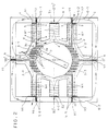
- Fig.1 is a plan view illustrating a magnetic circuit of a rotator basically according to the present invention.
- Fig.2 is a plan view of magnetic flow generated in the magnetic circuit of the rotator according to the present invention.
- Fig.3(A) and (B) are other embodiments of the rotator according to the present invention.
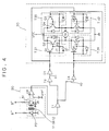
- Fig.4 is a diagram of a switching circuit according to the present invention.
- Fig.5 is an exploded perspective view of the rotator according to the present invention.
- Fig.1 is a basically illustrated plan view of a rotator according to the present invention.
- the rotator according to the present invention is largely divided into three components ; mechanical power generation means, electric power generation means, and magnetic flux circulation induction means.
- a revolving field magnet 2 fixed at a rotation axis 1 is located in the middle of the all means.
- the revolving field magnet 2 is made of a electromagnet to be magnetized by current, or a permanent magnet.
- the mechanical power generation means comprises the revolving field magnet 2 and one or more armatures 3 for generating the mechanical power.
- armatures 3 for generating the mechanical power At a plurality of magnetic pole sides of the armatures 3 for generating the mechanical power, many conductors of slot type 3a and 3b are formed being insulated and coils 3c are wound for applying a magnetic field to the revolving field magnet 2.
- the armatures 3 for generating the mechanical power comprise a first armature 3-1, a second armature 3-2, a third armature 3-3, and a fourth armature 3-4 which have the same and symmetric structure.
- the electric power generation means comprises the revolving field magnet 2 and one or more armatures 4 for generating the electric power by receiving magnetic flux during the rotation of the revolving field magnet 2.
- armatures 4 for generating the electric power many conductors are formed of slot or plane type and also wound by coils 4-3 for generating the electric power.
- the armatures 4 for generating the electric power comprise a first armature 4-1 and a second armature 4-2.
- the magnetic flux circulation induction means is formed of one body not only with the armatures 3 for generating mechanical power but also with the armatures 4 for generating electric power.
- electromagnets 5 are formed of a ferromagnetic material such as both armatures 3 and 4 for generating the mechanical and connected with each through wound coils 5-3 and 5-4.
- the induction electromagnets 5 for circulating the induced magnetic flux comprise a first to a fourth induction electromagnets 5-1, 5-2, 5-5 and 5-6.
- the induction electromagnets 5 can be formed into various shape of bar, triangle, circle, prominence and depression, T,H, or Y-type.
- the magnetic flux circulation induction means includes circulation conductors 6 for circulating the induced magnetic flux at the induction electromagnets 5.
- the circulation conductors 6 are made of the ferromagnetic material and comprise a first conductor 6-1 and a second conductor 6-2.
- the revolving field magnet 2 has a symmetric structure of the same left and right sides of the rotation axis 1.
- a coil 4-3 wound around an armature 4-1 for generating the electric power which is included in the electric power generation means, is taken out as an input P1 and the electromotive force is generated through the coil 4-3 when the magnetic flux is crossed thereto.
- a first and a second induction electromagnets 5-1 and 5-2 for circulating the magnetic flux are included in the magnetic flux induction means and wound with coils 5-3 and 5-4 in a constant direction, so that an identical magnetic field is formed and a pair of input lines P3 and P4 are are taken out from the coils 5-3 and 5-4 respectively in order to provide the electric power.
- a pair of output lines P1, P2 and two pairs of input lines P3, P4 and P5, P6 can be taken out from the coils.
- the revolving field magnet 2 is formed of a permanent magnet, if its N pole is located at the position of 180 degrees while its S pole is located at the position of zero degree, the coils 5-3 and 5-4 wound around the first and the second induction electromagnets 5-1 and 5-2 are magnetized by switching power supply applied to the input lines P3 and P4.
- FIG.2 A magnetic field to be generated by the induction electromagnets 5-1 and 5-2 is shown in Fig.2.
- the flow of the magnetic field is generated in the rotator of the present invention as shown in Fig.1.
- the N pole is formed around the center portions "a" of the magnetic pole sides by the law of the right-handed screw, while the S pole is formed around the center portions "b" of the magnetic pole sides.
- the N pole is then formed around the portion "c" of the magnetic pole side of the first induction electromagnet 5-1, and the N pole is also formed around the center portions "d” of the magnetic pole sides of the induction electromagnets 5-1 and 5-2 for circulating the magnetic flux which are connected to the armatures 4 for generating the electric power.
- the S pole is formed around the center portions "d” as the opposite polarity of the N pole.
- the switching power is supplied to the coil 3c wound around the slots 3a and 3b through terminals P11 and P12 as shown in Fig.1. Then the N pole is induced to the center portions "f" of the slots 3a and 3b of the armature 3-1 for generating the mechanical power and the S pole is induced to the positions "g", so the revolving field magnet 2 is repulsed by the same polarity with the induced pole at the center portions "f" of the sides.
- the revolving field magnet 2 is rotated by the repulsive force of the first armature 3-1 for generating the mechanical power and the attractive force of the first armature 4-1 for generating the electric power due to the induced S pole around the portion "e" of the magnetic pole side of the armature 4-1 for generating the electric power.
- the third armature 3-3 which is shown at the left side of the drawing generates the repulsive force to the revolving field magnet 2 and the second armature 4-2 for generating the electric power generates the attractive force so that the revolving field magnet 2 rotates around the axis 1.
- we can obtain the mechanical power by applying the repulsive and attractive force to the revolving field magnet 2 with the switching power supply to the coil 3c wound around the first and the third armatures 3-1 and 3-3 first, and next to a second and fourth armatures 3-2 and 3-4.
- the revolving field magnet 2 can be rotated by providing the switching power supply to the first, the second, the third and the fourth armatures 3-1, 3-2, 3-3 and 3-4 in sequence order for a constant duration.
- the rotation of the revolving field magnet 2 can be interrupted.
- the aagnetic flux toward the S pole around the portion "e” can be reduced arbitrarily by adjusting gaps Z1 and Z2 at the rear of the magnetic pole of the armature 4-1. Therefore, when the electromotive force is generated at the first armature 4-1, the electromotive force of the opposite direction is also generated at the second armature 4-2, so that the current due to the electromotive force flows through the output lines P1 and P2 of the coils 4-3 and 4-4.
- the coils 5-3 and 5-4 wound around the induction electromagnets 5-1 and 5-2 are applied for a primary coil of a transformer, while the coils 4-3 and 4-4 of the first and the second armatures 4-1 and 4-2 are applied for a the secondary coil of the transformer, since the magnetic flux flows through the first and second induction electromagnets 5-1 and 5-2.
- the induced current is able to flow and then a certain amount of the flux due to the induced current is supplied additionally when the revolving field magnet 2 rotates. Therefore, we can obtain a considerable amount of the electromotive force and take out the electric power from the output coil lines P1 and P2.
- Fig.3(A) and (B) show a diagram of driving state of the rotator according to embodiment of the modified structures of the electromagnets 5 and the circulation conductors 6 for the circulating the magnetic flux which are included in the magnetic flux induction means.
- the basic structures of the first, the second, the third and the fourth armatures 3-1, 3-2, 3-3 and 3-4 for generating the mechanical power, the first and the second armatures 4-1 and 4-2 for generating the electric power, the first and the second induction electromagnets 5-1 and 5-2, and the circulation conductors 6-1 and 6-2 are formed of similar structure in general.
- the switching power supply circuit 30 provides the electric power to the armature 3 and the magnetic flux circulation induction electromagnets 5.
- the N pole is induced to the third induction electromagnet 5-5 located at the left and lower side as shown in Fig.3(A).
- the N pole is induced to the first armature 3-1 for generating mechanical power while the S pole is also induced to the second induction electromagnet 5-2 located at the right and lower side, then the attractive force is provided to the revolving field magnet 2.
- the repulsive force is provided to the revolving field magnet 2 so as to rotate the revolving field magnet 2.
- the third induction electromagnet 5-5 induces the N pole to the second armature 4-2 at the left side and the magnetic flux of the N pole of the revolving field magnet 2 flows toward the S pole of the second armature 4-2.
- the S pole is induced to the first armature 4-1 from the second induction electromagnet 5-2 and the revolving field magnet 2 at the same time.
- the coil 4-4 wound around the left armature 4-2 and the coil 4-3 wound around the right armature 4-1 traverse the magnetic flux so as to generate electromotive force.
- a phase detector 20 detects the phase of the revolving field magnet 2 and the switching power supply circuit 30 converts the electric polarity of each armature, induction electromagnet and the like to rotate the revolving field magnet 2 continuously.
- the N pole is induced to the third armature 3-3 located at the left and lower side, while the S pole is induced to the fourth armature 3-4 located at the left and upper side.
- the N pole is induced to the second armature 3-2, while the S pole is induced to the first armature 3-1, so the revolving field magnet 2 can rotate continuously.
- the magnetic polarity of the first and the second induction electromagnets 4-1 and 4-2 is changed by every phase of 180 degrees of the revolving field magnet 2 and that of the armatures 3 is also changed by every phase of 90 degrees. And, the angles are adjustable.
- the switching power supply circuit 30 is necessary to change the phase of the revolving field magnet 2 as shown in Fig.4.
- Fig.4 shows a diagram of an example of the switching power supply circuit 30 which supplies the switching power to the rotator according the present invention.
- the circuit changes the polarity by every phase of 180 degrees of the revolving field magnet 2.
- the revolving field magnet phase detector 20 for detecting the phase of the revolving field magnet 2 includes a photosensor 31 comprising a photodiode PD and a phototransistor PQ.
- the first and the second phase-detecting plates 11 and 12 (shown in Fig.4) connected to the axis 1 of the revolving field magnet 2 are located between the photodiode PD and the phototransistor PQ for detecting rotated angles.
- An output terminal of the phototransistor PQ is connected to a comparator CP so that one output of the comparator CP is compared with a reference voltage and another output of the comparator CP is provided to different nodes n1 and n2 through inverters 11 and I2.
- the output of the node n1 is also connected to the switching power supply circuit 30 through an inverter I3, while the output of the node n2 is connected to the switching power supply circuit 30 through an inverter I4.
- the switching power supply circuit 30 comprises a first, a second a third and a fourth switching parts, T31, T32, T33 and T34 for providing the electric power to the rotator 10, the switching parts T33 and T34 being driven reversly in relation to the switching part T31 and T32.
- the switching parts T31, T32 and T33, T34 have the same configuration, in which the first switching part T31 comprises darlington transistors Q1 and Q2, voltage-dividing resistors R1 and R2, and diodes D1 and D2 to prevent the switching voltage from reverse.
- transistors Q1 and Q2 of the first switching part T31 and transistors Q7 and Q8 of the second switching part T32 are turned on at the same time.
- transistors Q3 and Q4 in the switching part T33 and transistors Q5 and Q6 in the switching part T34 are also turned on at the same time so that the rotator 10 is supplied with a switching pulse voltage of which phase is 180 degrees.
- the switching power supply circuit 30 changes the direction of the current applied to the induction electromagnets 5-1 and 5-2 whenever the revolving field magnet 2 changes by every 180 degrees.
- the switching current to be supplied to the first armature 3-1 to the fourth armature 3-4 is provided through the switching power supply circuit 30 in the same manner, since the switching power supply circuit 30 includes the second phase-detecting plate 12 to be sensed in the revolving field magnet phase detector 20 in which a photosensor 31 detects the second phase-detecting plate 12 by every 90 degrees of the revolving field magnet 2.
- the comparator CP of the revolving field magnet phase detector 20 in the switching power supply circuit 30 compares the reference voltage vref applied to an inverting input terminal (-) with an output voltage of the photosensor 31 applied to a noninverting input terminal (+).
- the photosensor 31 detects the rotated angle of the first phase-detecting plate 11 connected to the axis 1 of the revolving field magnet 2 (shown in Fig.4), so as to provide a low level signal to the noninverting terminal (+) of the comparator CP and turn on the phototransistor PQ if the light of the photodiode PD is transmitted, while a high level signal (B+) is provided when the light is not transmitted.
- the output becomes high level after passing through the inverters I1, I2 and I3.
- This high level signal makes the first and the second switching parts T31 and T32 turn on so that the current flows to the rotator 10.
- the high level signal applied to the first switching part 31 makes the transistors Q1 and Q2 turn on and the diodes D1 and D2 prevent the switching voltage from reversing.
- the high level signal after passing through the only inverter I1 becomes low level again through the inverter I4 and the low level signal is applied to the third and the fourth switching parts T33 and T34, thereby to keep them turn off.
- the high level signal which passed through the inverters I1 and I2 becomes the low level after passing through the inverter I3 to be applied to the first and the second switching parts T31 and T32 so that the switching parts T31 and T32 keep the turn off state.
- the high level signal passed through the inverters I1 and I4 is applied to the third and the fourth switching parts T33 and T34 so that they are turned on and the current flows to the rotator 10.
- the current has an opposite direction in relation to that of the first and the second switching part T31 and T32 which are turned on.
- phase detector 20 detects the angle of the first-phase detecting plate 11 as shown in Fig.5, a square-wave current which is switched by every 180 degrees of the revolving field magnet 2 must be provided in turns to the two pairs of input lines P3, P4 and P5, P6 in the rotator 10. And, in case that the phase detector 20 is used to detect the angle of the second phase-detecting plate 12, the square-wave current is provided in sequence order to the first armature 3-1 to the fourth armature 3-4 by every 90 degrees of the revolving field magnet 2.
- Fig.5 shows an embodiment of the rotator according to the present invention.
- the revolving field magnet 2 is formed by the electromagnet wound with coils or a permanent magnet and provided with a hole in its center for inserting the rotation axis 1.
- the first and the second phase detecting plates 11 and 12 are attached to the rotation axis 1.
- the first phase-detecting plate 11 controls the direction of the current applied to the coils 4-3 and 4-4 wound around the first and the second induction electromagnets 4-1 and 4-4 for generating the N and S poles.
- the second phase-detecting plate 12 controls the supply of the current through the coil 3c wound around the slots 3a of the first armature 3-1 to the fourth armature 3-4.
- the peripheral of the first and the second phase detecting plates 11 and 12 is cut as the desired angle so as to control the transmission time of the photosensor 31.
- a first and a second photosensor frames 21 and 22 are attached to both left and right sides of the first and the second phase-detecting plates 11 and 12 respectively, thereto the photosenser 31 is attached.
- the photosensor frames 21 and 22 are formed of " " shape and provided with wires 15 and 15′ for supplying the electric power.
- the rotation-phase detector 20 includes the first and the second phase-detecting plates 11 and 21, the first and the second photosensor frames 12 and 22, and the photosensor 31 to be attached to the photosensor frames 21 and 22.
- slip rings 13 are formed on peripheral of the axis 1 and connected to brushes 14 so that the direction of the current provided to the coils to be magnetized in the revolving field magnet 2 can be controlled.
- the armatures 4 for generating the electric power are divided into the first armature 4-1 and the second armature 4-2, and each armature 4-1 and 4-2 is fixed inside a cylindrical field plate 25 by screws 16 and 17.
- the coils for generating the electric power are wound around the armatures 4-1 and 4-2.
- the magnetic pole sides of the armatures 3 for generating the mechanical power are made of insulated conductors in the form of slots 3a and 3b wound with the coil 3c, and fixed on the inside of the cylindrical field plate 25 by screw.
- the armatures 3 for generating the mechanical power include the first armature 3-1 to the fourth armature 3-4 to be arranged in cylindrical field plate 25 symmetrically.
- the induction electromagnets 5 are made of the ferromagnetic material in the same manner with the armatures 3 and 4 as shown in Fig.1 and fixed inside of the cylindrical field plate 25.
- the cylindrical field plate 25 is to be the circulation conductor 6 in Fig.1.
- the armatures 3 for generating the mechanical power the armatures 4 for generating the electric power and the induction electromagnets 5 for circulating the magnetic flux are fixed inside the cylindrical field plate 25, the revolving field magnet 2 is inserted into its center hole and fixed together with the rotation-phase detector 20. Housings 27 and 29 provided with bearings 26 and 28 are joined to both left and right sides of the rotation axis 1 for fixing the position of the revolving field magnet 2, and then the rotator 10 is completed by screwing on.
- the phase-detected signals is provided to the switching power supply circuit 30 in Fig.4 by the first and the second phase-detecting plates 11 and 12 which rotate along with the revolving field magnet 2.
- magnetic fields are formed around the armatures 3 for generating the mechanical power and the induction electromagnets 5 according to the switching power supply circuit 30 correspondingly to the position of the revolving field magnet 2. This magnetic field gives the attractive and repulsive force to the revolving field magnet 2 for rotating around the axis 1 so as to obtain the mechanical power.
- both flux through the induction electromagnets 5 and the revolving field magnet 2 are induced toward the armatures 4 for generating the electric power to cross the wound coils 5-3 and 5-4 vertically so as to generate the electromotive force, the mechanical power and the electric power can be obtained at the same time.
- the 20 percent of the magnetic flux of the field magnet can be recovered to the electric energy, even though the input-to-output recovery ratio of energy is not 1 to 1. So that the external energy supply can be largely reduced due to the recovered energy.
- the rotator according the the present invention can be used in various fields such as the engines of the electric motorcars, ships, airplanes and heavy equipment, motors of controllers, various medical instruments, robot controllers, and magnet brakes.
- the current position of the revolving field magnet 2 is detected by the phase-detector 20 for generating the magnetic field to rotate the revolving field magnet 2, and then the electric power is provided in a selected direction to the one or more induction electromagnets 5 and one or more armatures 3 for generating the mechanical power. Therefore, the current is provided to the first armature 3-1 to the forth armature 3-4 in sequence order and the mechanical power is obtained by the attractive or repulsive forces of the revolving field magnet 2. Also, the magnetic flux caused by the current flowing through the electromagnets 5-1,5-2, 5-5 and 5-6 and the magnetic flux generated at the revolving field magnet 2 are concentrated toward the armatures 4 for generating the electric power to generate the electromotive force.
- the first electromagnet 5-1 to the fourth electromagnet 5-6 are provided with slits X1-X4 to increase the efficiency of the magnetic flux, as shown in Fig.2, thereby for generating the magnetic reluctance for the induced magnetic flux to circulate in a predetermined direction, as shown by the arrows, in the first and the second circulation conductors 6-1 and 6-2.
- the first and the second circulation conductors 6-1 and 6-2 is provided with slits Y1 to Y5.
- These slits X1-X4 and Y1-Y5 are formed by cutting the electromagnets and the conductors in a constant distance.
- the efficiency of the slits can be improved by inserting the antiferromagnetic material or the diamagnetic material.
- the induction electromagnets 5 are provided with slits Z1 and Z2 for improving the circulation efficiency of the magnetic flux, since the armatures 3 and 4 for generating the mechanical power and the electric power and the induction electromagnets are made of the ferromagnetic material to induce the magnetic field strongly according to the direction of the current.
- the strong magnetic field can be induced due to their high magnetic permeability of the core.
- the slits Z1 and Z2 can also be formed at the rear of the armatures 4 thereby for reducing the magnetic flux of the center portion e arbitrarily since the rotating motion of the revolving field magnet 2 is interrupted.
- the present invention described hereinabove has characteristics, in which consumption of the external electric energy can be minimized by generating the mechanical power and the electric power at the same time and applying the generated electric power to the rotator again in such a manner that the magnetic field to rotate revolving field magnet is formed by switching power supply at the one or more armatures for generating the mechanical power and both of the magnetic flux of the revolving field naguet and the magnetic flux of the induction electromagnets and the circulation conductors are supplied to the armatures for generating the electric power so that the rotating mechanical power and the electric power are generated at the same time.
- the rotator has been described in 2 poles and 4 phases configuration, it can be, however, applied in 2 pole and 3 phases or multi-pole configuration in the same manner.
Landscapes
- Engineering & Computer Science (AREA)
- Power Engineering (AREA)
- Permanent Magnet Type Synchronous Machine (AREA)
- Manipulator (AREA)
- Sealing Using Fluids, Sealing Without Contact, And Removal Of Oil (AREA)
- Sealing Devices (AREA)
Abstract
Claims (17)
- Circuit magnétique d'une machine tournante pour recevoir de l'énergie électrique externe et générer de l'énergie électrique et de l'énergie mécanique, comportant :a) un aimant de champ tournant (2) destiné à tourner sous l'effet des forces d'attraction et de répulsion d'un champ magnétique tournant ;b) des moyens de génération d'énergie mécanique (3) pour appliquer ledit champ magnétique tournant audit aimant tournant (2), comportant une ou plusieurs armatures (3-1, 3-2, 3-3, 3-4) et une pluralité de conducteurs (3a, 3b) du type à encoche au niveau des faces polaires magnétiques de celles-ci, portant des enroulements (3c) ;caractérisé par :c) des moyens de génération d'énergie électrique (4) formés par des conducteurs, comportant une ou plusieurs armatures (4-1, 4-2) pour générer l'énergie électrique lors de la réception d'un flux magnétique généré lorsque ledit aimant de champ tournant (2) tourne et des enroulements (4-3, 4-4) enroulés autour desdites armatures (4-1, 4-2) ; etd) des moyens d'induction de flux magnétique (5) comportant un ou plusieurs électroaimants à induction (5-1, 5-2, 5-5, 5-6) formés par les armatures des moyens de génération d'énergie mécanique (3) et les armatures des moyens de génération d'énergie électrique (4) sur lesquelles sont enroulés des enroulements (5-3, 5-4) pour contrôler l'écoulement dudit flux magnétique en fonction de la position dudit aimant de champ tournant (2), et comportant de plus des conducteurs ce circulation (6-1, 6-2, 6) pour faire circuler le flux magnétique induit dans lesdits électroaimants à induction (5-1, 5-2, 5-5, 5-6).
- Circuit magnétique selon la revendication 1, dans lequel ledit aimant de champ tournant (2) est formé par un aimant permanent ou un électroaimant sur lequel sont enroulés des enroulements destinés à être magnétisés.
- Circuit magnétique selon la revendication 1, dans lequel lesdits électroaimants à induction (5-1, 5-2, 5-5, 5-6) inclus dans les moyens d'induction de flux magnétique (5) comportent des premier à quatrième électroaimants (5-1, 5-2, 5-5, 5-6) et sont formés de façon à être fixés auxdites une ou plusieurs armatures desdits moyens de génération d'énergie mécanique (3) et desdits moyens de génération d'énergie électrique (4), ou formés d'un conducteur unique.
- Circuit magnétique selon la revendication 1, dans lequel une paire de lignes de sortie (P1, P2) sont raccordées aux enroulements (4-3, 4-4) enroulés autour d'une première et d'une deuxième armatures (4-1, 4-2) desdites armatures desdits moyens de génération d'énergie électrique (4), et deux paires de lignes d'entrée (P3, P4 ; P5, P6) sont raccordées aux enroulements (5-3, 5-4) enroulés autour d'un premier et d'un deuxième électroaimants à induction (5-1, 5-2) desdits moyens d'induction de flux magnétique (5) et à des enroulements enroulés autour d'un troisième et d'un quatrième électroaimants à induction (5-5, 5-6).
- Circuit magnétique selon la revendication 1, dans lequel un alliage supraconducteur est fixé aux côtés induits par le flux magnétique des armatures (4-1, 4-2) des moyens de génération d'énergie électrique (4) qui reçoivent le flux magnétique dudit aimant de champ tournant (2).
- Circuit magnétique selon la revendication 1, dans lequel les électroaimants à induction (5-1, 5-2, 5-5, 5-6) inclus dans les moyens d'induction de flux magnétique (5) sont formés sous l'une des formes suivantes : barre, triangle, cercle, forme proéminente et dépression, forme du type en T, en H ou en Y.
- Circuit magnétique selon l'une quelconque des revendications 1 à 6, dans lequel les fentes (X1 à X4) pour la réluctance magnétique sont formées au niveau des électroaimants à induction (5-1, 5-2, 5-5, 5-6) pour réduire ou augmenter la force du flux magnétique pour la partie nécessaire.
- Circuit magnétique selon l'une quelconque des revendications 1 à 7, dans lequel des fentes (Y1 à Y5) pour la réluctance magnétique sont formées au niveau des conducteurs de circulation (6-1, 6-2, 6) pour contrôler l'écoulement du flux magnétique.
- Circuit magnétique selon l'une quelconque des revendications 1 à 8, dans lequel des fentes (W1 à W4) pour la réluctance magnétique sont formées entre lesdites une ou plusieurs armatures desdits moyens de génération d'énergie mécanique (3) et lesdites une ou plusieurs armatures desdits moyens de génération d'énergie électrique (4) qui forment, réunies, lesdits électroaimants à induction (5-1, 5-2, 5-5, 5-6).
- Circuit magnétique selon l'une quelconque des revendications 1 à 9, dans lequel des fentes (Z1, Z2) sont formées à l'arrière des pôles magnétiques de l'armature ou des armatures (4-1, 4-2) des moyens de génération d'énergie électrique (4).
- Circuit magnétique selon l'une quelconque des revendications 7 à 9, dans lequel des matériaux diamagnétiques ou des matériaux anti-ferromagnétiques sont insérés dans lesdites fentes afin d'améliorer l'efficacité de la réluctance magnétique.
- Circuit magnétique selon l'une quelconque des revendications précédentes, comportant de plus :
un détecteur de phase (20) pour détecter la phase dudit aimant de champ tournant (2) et pour délivrer celle-ci à un circuit d'alimentation de commutation (30) pour délivrer ladite énergie électrique externe à l'armature ou aux armatures (3-1, 3-2, 3-3, 3-4) desdits moyens de génération d'énergie mécanique (3) et auxdits électroaimants à induction (5-1, 5-2, 5-5, 5-6) desdits moyens d'induction de flux magnétique (5). - Circuit magnétique selon la revendication 12, dans lequel ledit détecteur de phase (20) comporte :
un photodétecteur (31) comportant une photodiode (PD) et un phototransistor (PQ) ;
un comparateur (CP) pour comparer une tension de sortie dudit photodétecteur (31) et une tension de référence (Vref) ; et
un circuit pour délivrer à l'alimentation de commutation (30) une sortie dudit comparateur (CP). - Circuit magnétique selon la revendication 12, dans lequel lesdites armatures desdits moyens de génération d'énergie mécanique (3), lesdites armatures desdits moyens de génération d'énergie électrique (4) et lesdits électroaimants à induction (5-1, 5-2, 5-5, 5-6) sont fixés au niveau d'une plaque métallique cylindrique (25), ledit aimant de champ tournant (2) est fixé à un axe de rotation (1) ; des première et deuxième plaques de détection de phase (11, 12) sont fixées audit axe de rotation (1) ; et des premier et deuxième bâtis de photodétecteur (21, 22) sont fixés entre des boîtiers gauche et droit (27, 29) à l'aide de paliers (26, 28) devant être insérés dans la plaque de métal cylindrique (25).
- Circuit magnétique selon la revendication 14, dans lequel ladite plaque de métal cylindrique (25) constitue ledit conducteur de circulation (6).
- Circuit magnétique selon la revendication 14 ou 15, comportant de plus :
des bagues collectrices (13) formées sur l'axe de rotation (1) pour changer la polarité magnétique dudit aimant de champ tournant (2) ; et
des balais (14) devant être connectés auxdites bagues collectrices (13) pour délivrer du courant électrique. - Procédé d'induction magnétique utilisant ledit circuit magnétique de la revendication 1, comportant les étapes suivantes :a) la détection de la position dudit aimant de champ tournant (2) ;b) la sélection de la direction d'un courant de l'énergie électrique externe ;c) la délivrance dudit courant auxdites armatures desdits moyens de génération d'énergie mécanique (3) et auxdits électroaimants à induction (5-1, 5-2, 5-5, 5-6) ; etd) l'induction du flux magnétique à travers les électroaimants à induction (5-1, 5-2, 5-5, 5-6) vers lesdites armatures (4-1, 4-2) des moyens de génération d'énergie électrique (4) portant lesdits enroulements (4-3, 4-4) au moyen desdits conducteurs de circulation (6-1, 6-2, 6).
Applications Claiming Priority (3)
| Application Number | Priority Date | Filing Date | Title |
|---|---|---|---|
| KR38290 | 1990-01-12 | ||
| KR1019900000382A KR950000241B1 (ko) | 1990-01-12 | 1990-01-12 | 동력발생 및 전력발생용 회전장치의 자기회로 및 자기유도 방법 |
| PCT/KR1990/000007 WO1991011051A1 (fr) | 1990-01-12 | 1990-07-20 | Procede d'induction magnetique et circuit magnetique de rotateur servant a generer la puissance mecanique et electrique |
Publications (2)
| Publication Number | Publication Date |
|---|---|
| EP0509993A1 EP0509993A1 (fr) | 1992-10-28 |
| EP0509993B1 true EP0509993B1 (fr) | 1995-03-15 |
Family
ID=19295283
Family Applications (1)
| Application Number | Title | Priority Date | Filing Date |
|---|---|---|---|
| EP90911445A Expired - Lifetime EP0509993B1 (fr) | 1990-01-12 | 1990-07-20 | Procede d'induction magnetique et circuit magnetique de rotateur servant a generer la puissance mecanique et electrique |
Country Status (7)
| Country | Link |
|---|---|
| US (1) | US5350991A (fr) |
| EP (1) | EP0509993B1 (fr) |
| JP (1) | JP2624574B2 (fr) |
| KR (1) | KR950000241B1 (fr) |
| AU (1) | AU6145590A (fr) |
| DE (1) | DE69017919T2 (fr) |
| WO (1) | WO1991011051A1 (fr) |
Families Citing this family (13)
| Publication number | Priority date | Publication date | Assignee | Title |
|---|---|---|---|---|
| CA2139584A1 (fr) | 1992-07-09 | 1994-01-20 | Takashi Nagate | Moteur sans balais |
| MY127916A (en) * | 1994-12-22 | 2006-12-29 | Sony Corp | Recording medium for protecting copyrighted data |
| EP0845171A1 (fr) * | 1995-08-16 | 1998-06-03 | Youn Soo Bae | Circuits magnetiques equipant un systeme rotatif de production d'energie mecanique et electrique |
| US5783894A (en) * | 1995-10-31 | 1998-07-21 | Wither; Thomas A. | Method and apparatus for generating electrical energy |
| US6727621B1 (en) | 2003-04-22 | 2004-04-27 | Northland/Scott Fetzer Company | Motor-based electrical power supply |
| US7545056B2 (en) * | 2003-05-27 | 2009-06-09 | Pratt & Whitney Canada Corp. | Saturation control of electric machine |
| US7262539B2 (en) * | 2004-11-26 | 2007-08-28 | Pratt & Whitney Canada Corp. | Saturation control of electric machine |
| DE10343293B4 (de) * | 2003-09-18 | 2009-06-10 | Siemens Ag | Elektrische Maschine mit Dämpfungseinrichtung |
| KR20080063747A (ko) * | 2005-08-12 | 2008-07-07 | 파워 그룹 인터내셔널 인코포레이티드 | 자기조절 영구자석 발전기 |
| FR2893780A1 (fr) * | 2005-11-22 | 2007-05-25 | Schneider Electric Ind Sas | Dispositif autonome de generation d'energie electrique |
| US7288923B1 (en) * | 2006-04-21 | 2007-10-30 | Pratt & Whitney Canada Corp. | Voltage-limited electric machine |
| US20140001764A1 (en) * | 2011-12-22 | 2014-01-02 | Humancar, Inc. | Human-Powered Electrical Generating Device |
| US10770937B2 (en) | 2019-01-03 | 2020-09-08 | A&I Services Incorporated | High efficiency power generation system and a method of operating same |
Family Cites Families (24)
| Publication number | Priority date | Publication date | Assignee | Title |
|---|---|---|---|---|
| US588491A (en) * | 1897-08-17 | Multipolar dynamo | ||
| AT90845B (de) * | 1915-11-19 | 1923-01-10 | Neuland Patents Ltd | Als Dynamomaschine und Mehrphasenumformer verwendbarer Motor, bei dem auf Läufer und Ständer Verzahnungen mit verschiedener Teilung vorgesehen sind. |
| US2378668A (en) * | 1943-05-24 | 1945-06-19 | Theodore W Vickers | Electrical machine |
| JPS5317731B2 (fr) * | 1971-08-09 | 1978-06-10 | ||
| US3885302A (en) * | 1973-07-27 | 1975-05-27 | Garrett Corp | Methods of making dynamoelectric machinery |
| US4005347A (en) * | 1974-06-24 | 1977-01-25 | General Electric Company | Electronically commutated motor and method of making same |
| JPS53126107A (en) * | 1977-04-12 | 1978-11-04 | Fujitsu Fanuc Ltd | Dc motor |
| DE2733719A1 (de) * | 1977-07-26 | 1979-02-15 | Chitta Ranjan Mukherjee | Generator |
| DE2734223B2 (de) * | 1977-07-29 | 1979-06-07 | Apparatebau Gauting Gmbh, 8035 Gauting | Winkelstellglied mit optischer Abtastung |
| US4228396A (en) * | 1978-05-26 | 1980-10-14 | Dataproducts Corporation | Electronic tachometer and combined brushless motor commutation and tachometer system |
| JPS55127854A (en) * | 1979-03-24 | 1980-10-03 | Fanuc Ltd | Dc machine having e-type commutating pole |
| JPS5947946B2 (ja) * | 1979-03-24 | 1984-11-22 | ファナック株式会社 | E型補極を有する直流機 |
| JPS55127889A (en) * | 1979-03-24 | 1980-10-03 | Sony Corp | Motor-driving circuit |
| US4360769A (en) * | 1979-09-07 | 1982-11-23 | Honeywell Inc. | Optical counting motor shaft positioner |
| JPS56112837A (en) * | 1980-02-12 | 1981-09-05 | Fanuc Ltd | Direct current machine with e type commutating pole |
| US4346335A (en) * | 1981-04-07 | 1982-08-24 | Mcinnis Stirling A | Speed control of a D.C. electric motor |
| US4631456A (en) * | 1982-03-22 | 1986-12-23 | The Charles Stark Draper Laboratory, Inc. | Inertial energy storage device and synchronous rotary electrical machine for use therein |
| US4712028A (en) * | 1984-05-21 | 1987-12-08 | Sigma Instruments, Inc. | Magnetically assisted stepping motor |
| US4642539A (en) * | 1985-06-10 | 1987-02-10 | Northern Magnetics, Inc. | Torque motor with unlimited angular excursion |
| US5173651A (en) * | 1985-06-28 | 1992-12-22 | Kollmorgen Technologies Corporation | Electrical drive systems |
| DE3740697A1 (de) * | 1987-12-01 | 1989-06-22 | Pfaff Ind Masch | Antriebsmotor |
| US4982123A (en) * | 1989-11-17 | 1991-01-01 | Sunstrand Corporation | Integrated exciter generator and rotating transformer |
| US5122697A (en) * | 1990-04-30 | 1992-06-16 | Emerson Electric Co. | Hybrid single-phase variable reluctance motor |
| JPH04236190A (ja) * | 1991-01-11 | 1992-08-25 | Toyota Motor Corp | ブラシレスモータのための電気制御装置 |
-
1990
- 1990-01-12 KR KR1019900000382A patent/KR950000241B1/ko not_active Expired - Fee Related
- 1990-07-20 JP JP2510929A patent/JP2624574B2/ja not_active Expired - Fee Related
- 1990-07-20 AU AU61455/90A patent/AU6145590A/en not_active Abandoned
- 1990-07-20 WO PCT/KR1990/000007 patent/WO1991011051A1/fr not_active Ceased
- 1990-07-20 US US07/910,074 patent/US5350991A/en not_active Expired - Fee Related
- 1990-07-20 DE DE69017919T patent/DE69017919T2/de not_active Expired - Fee Related
- 1990-07-20 EP EP90911445A patent/EP0509993B1/fr not_active Expired - Lifetime
Also Published As
| Publication number | Publication date |
|---|---|
| JPH05505089A (ja) | 1993-07-29 |
| KR950000241B1 (ko) | 1995-01-12 |
| DE69017919T2 (de) | 1995-08-31 |
| WO1991011051A1 (fr) | 1991-07-25 |
| EP0509993A1 (fr) | 1992-10-28 |
| JP2624574B2 (ja) | 1997-06-25 |
| US5350991A (en) | 1994-09-27 |
| DE69017919D1 (de) | 1995-04-20 |
| KR910015093A (ko) | 1991-08-31 |
| AU6145590A (en) | 1991-08-05 |
Similar Documents
| Publication | Publication Date | Title |
|---|---|---|
| US5350991A (en) | Magnetic induction method and magnetic circuit of rotator for generating mechanical and electric power | |
| JP2832307B2 (ja) | 電動機 | |
| US5202599A (en) | Electric motor | |
| JPS6360720A (ja) | 射出成形機駆動装置 | |
| JPH01318593A (ja) | 正逆回転可能なステッピングモータ及びその制御方法 | |
| ZA200104617B (en) | A system for controlling a rotary device. | |
| US3504253A (en) | Rotary stepping motor having a d-c winding and a pulsed winding | |
| US5525848A (en) | Magnetic bearing system including a generator | |
| US10291162B1 (en) | Flyback mode process harnessing generator action in electric motor | |
| US20230238857A1 (en) | Magnetic levitation system | |
| US20200067380A1 (en) | Electric machine having an axial electrodynamic bearing | |
| RU2069441C1 (ru) | Синхронная машина | |
| US6359358B1 (en) | Magnetic circuits in the rotation system for generating both the mechanical power and the electric power | |
| KR20030039945A (ko) | 유도전류를 이용한 회전기의 자기회로 | |
| US4968921A (en) | Electromagnetic motor with secondary stator coils | |
| Wang et al. | Analysis of a spherical permanent magnet actuator | |
| KR100978828B1 (ko) | 분할 코일체를 갖는 회전판과 분할 자석체를 갖는 고정판에의한 전동장치 | |
| JPS634414B2 (fr) | ||
| JPH06302428A (ja) | 永久磁石可変磁場発生装置 | |
| KR0122862B1 (ko) | 4상 교류서보모터의 권선구조 | |
| JPH0365040A (ja) | 同性磁極誘導発電機 | |
| JP3408558B2 (ja) | 直流リニアブラシレスモータの制御装置 | |
| DE3936662A1 (de) | Wicklungsanordnung bei schrittmotoren, die hoehere schrittgeschwindigkeiten bei hohem drehmoment und hohem haltemoment ermoeglicht | |
| GB2189087A (en) | Improvements in or relating to rotor assembly for an electric machine | |
| JPS6364564A (ja) | 超電磁誘導モ−タ− |
Legal Events
| Date | Code | Title | Description |
|---|---|---|---|
| PUAI | Public reference made under article 153(3) epc to a published international application that has entered the european phase |
Free format text: ORIGINAL CODE: 0009012 |
|
| 17P | Request for examination filed |
Effective date: 19920709 |
|
| AK | Designated contracting states |
Kind code of ref document: A1 Designated state(s): BE DE FR GB NL |
|
| 17Q | First examination report despatched |
Effective date: 19930705 |
|
| GRAA | (expected) grant |
Free format text: ORIGINAL CODE: 0009210 |
|
| AK | Designated contracting states |
Kind code of ref document: B1 Designated state(s): BE DE FR GB NL |
|
| ET | Fr: translation filed | ||
| REF | Corresponds to: |
Ref document number: 69017919 Country of ref document: DE Date of ref document: 19950420 |
|
| PLBE | No opposition filed within time limit |
Free format text: ORIGINAL CODE: 0009261 |
|
| STAA | Information on the status of an ep patent application or granted ep patent |
Free format text: STATUS: NO OPPOSITION FILED WITHIN TIME LIMIT |
|
| 26N | No opposition filed | ||
| REG | Reference to a national code |
Ref country code: GB Ref legal event code: IF02 |
|
| PGFP | Annual fee paid to national office [announced via postgrant information from national office to epo] |
Ref country code: GB Payment date: 20050819 Year of fee payment: 16 |
|
| PGFP | Annual fee paid to national office [announced via postgrant information from national office to epo] |
Ref country code: DE Payment date: 20050823 Year of fee payment: 16 |
|
| PGFP | Annual fee paid to national office [announced via postgrant information from national office to epo] |
Ref country code: BE Payment date: 20050909 Year of fee payment: 16 |
|
| PGFP | Annual fee paid to national office [announced via postgrant information from national office to epo] |
Ref country code: FR Payment date: 20050915 Year of fee payment: 16 |
|
| PGFP | Annual fee paid to national office [announced via postgrant information from national office to epo] |
Ref country code: NL Payment date: 20050929 Year of fee payment: 16 |
|
| PG25 | Lapsed in a contracting state [announced via postgrant information from national office to epo] |
Ref country code: GB Free format text: LAPSE BECAUSE OF NON-PAYMENT OF DUE FEES Effective date: 20060720 |
|
| PG25 | Lapsed in a contracting state [announced via postgrant information from national office to epo] |
Ref country code: BE Free format text: LAPSE BECAUSE OF NON-PAYMENT OF DUE FEES Effective date: 20060731 |
|
| PG25 | Lapsed in a contracting state [announced via postgrant information from national office to epo] |
Ref country code: DE Free format text: LAPSE BECAUSE OF NON-PAYMENT OF DUE FEES Effective date: 20070201 Ref country code: NL Free format text: LAPSE BECAUSE OF NON-PAYMENT OF DUE FEES Effective date: 20070201 |
|
| GBPC | Gb: european patent ceased through non-payment of renewal fee |
Effective date: 20060720 |
|
| NLV4 | Nl: lapsed or anulled due to non-payment of the annual fee |
Effective date: 20070201 |
|
| REG | Reference to a national code |
Ref country code: FR Ref legal event code: ST Effective date: 20070330 |
|
| BERE | Be: lapsed |
Owner name: *BAE YOUN SOO Effective date: 20060731 |
|
| PG25 | Lapsed in a contracting state [announced via postgrant information from national office to epo] |
Ref country code: FR Free format text: LAPSE BECAUSE OF NON-PAYMENT OF DUE FEES Effective date: 20060731 |