EP0510332A2 - Dispositif pour changer les moules dans une machine de vulcanisation de pneus - Google Patents
Dispositif pour changer les moules dans une machine de vulcanisation de pneus Download PDFInfo
- Publication number
- EP0510332A2 EP0510332A2 EP92103471A EP92103471A EP0510332A2 EP 0510332 A2 EP0510332 A2 EP 0510332A2 EP 92103471 A EP92103471 A EP 92103471A EP 92103471 A EP92103471 A EP 92103471A EP 0510332 A2 EP0510332 A2 EP 0510332A2
- Authority
- EP
- European Patent Office
- Prior art keywords
- mold
- station
- tire
- plate
- manipulator
- Prior art date
- Legal status (The legal status is an assumption and is not a legal conclusion. Google has not performed a legal analysis and makes no representation as to the accuracy of the status listed.)
- Granted
Links
Images
























Classifications
-
- B—PERFORMING OPERATIONS; TRANSPORTING
- B29—WORKING OF PLASTICS; WORKING OF SUBSTANCES IN A PLASTIC STATE IN GENERAL
- B29D—PRODUCING PARTICULAR ARTICLES FROM PLASTICS OR FROM SUBSTANCES IN A PLASTIC STATE
- B29D30/00—Producing pneumatic or solid tyres or parts thereof
- B29D30/06—Pneumatic tyres or parts thereof (e.g. produced by casting, moulding, compression moulding, injection moulding, centrifugal casting)
-
- B—PERFORMING OPERATIONS; TRANSPORTING
- B29—WORKING OF PLASTICS; WORKING OF SUBSTANCES IN A PLASTIC STATE IN GENERAL
- B29D—PRODUCING PARTICULAR ARTICLES FROM PLASTICS OR FROM SUBSTANCES IN A PLASTIC STATE
- B29D30/00—Producing pneumatic or solid tyres or parts thereof
- B29D30/06—Pneumatic tyres or parts thereof (e.g. produced by casting, moulding, compression moulding, injection moulding, centrifugal casting)
- B29D30/0601—Vulcanising tyres; Vulcanising presses for tyres
- B29D30/0662—Accessories, details or auxiliary operations
-
- B—PERFORMING OPERATIONS; TRANSPORTING
- B29—WORKING OF PLASTICS; WORKING OF SUBSTANCES IN A PLASTIC STATE IN GENERAL
- B29C—SHAPING OR JOINING OF PLASTICS; SHAPING OF MATERIAL IN A PLASTIC STATE, NOT OTHERWISE PROVIDED FOR; AFTER-TREATMENT OF THE SHAPED PRODUCTS, e.g. REPAIRING
- B29C31/00—Handling, e.g. feeding of the material to be shaped, storage of plastics material before moulding; Automation, i.e. automated handling lines in plastics processing plants, e.g. using manipulators or robots
- B29C31/006—Handling moulds, e.g. between a mould store and a moulding machine
-
- B—PERFORMING OPERATIONS; TRANSPORTING
- B29—WORKING OF PLASTICS; WORKING OF SUBSTANCES IN A PLASTIC STATE IN GENERAL
- B29C—SHAPING OR JOINING OF PLASTICS; SHAPING OF MATERIAL IN A PLASTIC STATE, NOT OTHERWISE PROVIDED FOR; AFTER-TREATMENT OF THE SHAPED PRODUCTS, e.g. REPAIRING
- B29C33/00—Moulds or cores; Details thereof or accessories therefor
- B29C33/02—Moulds or cores; Details thereof or accessories therefor with incorporated heating or cooling means
- B29C33/04—Moulds or cores; Details thereof or accessories therefor with incorporated heating or cooling means using liquids, gas or steam
-
- B—PERFORMING OPERATIONS; TRANSPORTING
- B29—WORKING OF PLASTICS; WORKING OF SUBSTANCES IN A PLASTIC STATE IN GENERAL
- B29C—SHAPING OR JOINING OF PLASTICS; SHAPING OF MATERIAL IN A PLASTIC STATE, NOT OTHERWISE PROVIDED FOR; AFTER-TREATMENT OF THE SHAPED PRODUCTS, e.g. REPAIRING
- B29C33/00—Moulds or cores; Details thereof or accessories therefor
- B29C33/30—Mounting, exchanging or centering
- B29C33/305—Mounting of moulds or mould support plates
-
- B—PERFORMING OPERATIONS; TRANSPORTING
- B29—WORKING OF PLASTICS; WORKING OF SUBSTANCES IN A PLASTIC STATE IN GENERAL
- B29C—SHAPING OR JOINING OF PLASTICS; SHAPING OF MATERIAL IN A PLASTIC STATE, NOT OTHERWISE PROVIDED FOR; AFTER-TREATMENT OF THE SHAPED PRODUCTS, e.g. REPAIRING
- B29C35/00—Heating, cooling or curing, e.g. crosslinking or vulcanising; Apparatus therefor
- B29C35/02—Heating or curing, e.g. crosslinking or vulcanizing during moulding, e.g. in a mould
-
- B—PERFORMING OPERATIONS; TRANSPORTING
- B29—WORKING OF PLASTICS; WORKING OF SUBSTANCES IN A PLASTIC STATE IN GENERAL
- B29D—PRODUCING PARTICULAR ARTICLES FROM PLASTICS OR FROM SUBSTANCES IN A PLASTIC STATE
- B29D30/00—Producing pneumatic or solid tyres or parts thereof
- B29D30/06—Pneumatic tyres or parts thereof (e.g. produced by casting, moulding, compression moulding, injection moulding, centrifugal casting)
- B29D30/0601—Vulcanising tyres; Vulcanising presses for tyres
- B29D30/065—Tyre-vulcanising presses with two or more moulds, e.g. stacked upon each other
- B29D2030/0651—Tyre-vulcanising presses with two or more moulds, e.g. stacked upon each other the moulds being arranged side by side, or in a circle
-
- Y—GENERAL TAGGING OF NEW TECHNOLOGICAL DEVELOPMENTS; GENERAL TAGGING OF CROSS-SECTIONAL TECHNOLOGIES SPANNING OVER SEVERAL SECTIONS OF THE IPC; TECHNICAL SUBJECTS COVERED BY FORMER USPC CROSS-REFERENCE ART COLLECTIONS [XRACs] AND DIGESTS
- Y10—TECHNICAL SUBJECTS COVERED BY FORMER USPC
- Y10S—TECHNICAL SUBJECTS COVERED BY FORMER USPC CROSS-REFERENCE ART COLLECTIONS [XRACs] AND DIGESTS
- Y10S425/00—Plastic article or earthenware shaping or treating: apparatus
- Y10S425/20—Molding plants
- Y10S425/201—Diverse stations
Definitions
- the present invention relates to a mold changing apparatus for use in a tire vulcanizer having a plurality of mold stations.
- a typical conventional tire vulcanizing press is equipped with a tire mold that fits tires to be produced.
- the tire mold necessitates washing the inner surface thereof periodically, and it also needs to be replaced with another in the middle of production to change the size of tires to be produced or the pattern formed on the tire surface.
- the tire mold which is contaminated during production, is removed from the tire vulcanizing press for washing and remounted thereto after washing.
- the replacement is performed by canceling the clamping between the top press-heating plate on the press side and the top half of the mold and the clamping between the bottom press-heating plate on the press and the bottom half of the mold (in many cases the clamping is effected by using bolts), and taking the mold out of the press by use of a forklift truck or an overhead traveling crane, and then mounting a new mold by executing a procedure reverse to the above.
- the conventional tire vulcanizing press comprises various constituent devices, such as devices that display their functions only during the vulcanizing cycle, devices that display their functions only during the loading and unloading cycle, and devices that function during both the cycles.
- the vulcanizing cycle is about 10 minutes, while the loading and unloading cycle is about 1 minute.
- the loading and unloading process accounts for only about 10% of the production cycle, whereas the percentage of the total installation cost that is taken up by the loading and unloading equipment exceeds this level by a large margin.
- the cost proportion of the loading and unloading equipment is higher than that in the case of production of conventional tires.
- the shaping method (part of the loading process) disclosed in Japanese Patent Laid-Open (KOKAI) No. 02-200405 (1990) needs a complicated mechanism, which is not provided in the conventional press, so that the proportion taken up by the loading and unloading cost is high, although this method has been proved by an actual machine to be suitable for production of tires of higher accuracy.
- a mold preparing station is provided in the middle or terminal of a row of stationary tire molds so that it is possible to complete in this mold preparing station automatic centering of a new mold which is to replace an old one and preheating of the new mold to the same temperature as that in the production process.
- a mold can be installed in the mold preparing station only by an operator of a forklift or a crane, whereas an assistant to the operator has heretofore been needed in the prior art.
- a mold which is to be removed is automatically received from the mold station, transferred to the vicinity of the new mold in the mold preparing station and separated by a manipulator. Subsequently, the manipulator automatically receives the new mold which has already been heated, thereby enabling fully-automatic mold change.
- the manipulator is equipped with devices that are used for various operations carried out at each individual mold station, for example, operations of opening and closing a press, loading a green tire and removing the completed tire, and the manipulator is used for all the mold stations in common.
- Heating fluid supply and discharge systems can be automatically connected and disconnected at the time of the operation of opening and closing the press at each mold station.
- heating fluid supply and discharge systems for splittable mold parts can be automatically connected and disconnected at the time of replacement of a mold.
- a mold that has been centered and preheated completely in the mold preparing station is received by the mold open-close manipulator, and it is then transferred to and installed in a mold station where vulcanization is executed. These operations are all automatically carried out.
- a mold which is to be removed is automatically received from the mold station by the manipulator, and it is automatically transferred to the vicinity of the new mold in the mold preparing station and separated by the manipulator. Subsequently, the manipulator automatically receives the new mold which has already been heated. Thus, fully-automatic mold change is realized.
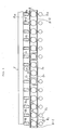
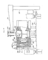
- mold stations A 1 to A 12 have tire molds installed therein, respectively.
- Green tire preparing stations E 1 to E 12 are disposed in front of the mold stations A 1 to A, 2, and discharge conveyors G 1 to G 12 2 and a belt conveyor F are disposed in the rear of the mold stations A 1 to A l 2 .
- the mold stations A 1 to A 12 2 are disposed at proper spacings on a common base frame B.
- a track is installed on the common base frame B for guiding a movable mold open-close manipulator C, which is moved and stopped in position at the request of each mold station A to execute operations of opening and closing a mold, loading a green tire, and unloading the completed tire.
- the system is provided with one or two manipulators C, which are denoted by reference numerals C 1 and C 2 .
- the number of manipulators is preferably two from the viewpoint of maintenance and the possibility that two mold stations will make a request at the same time.
- the number of mold stations is determined by considering the time required for the manipulator C to move and the time consumed in operations of opening and closing the mold, loading a green tire and unloading the completed tire at each station, together with the vulcanizing time (i.e., the period of time during which the mold is closed) at each mold station.
- the vulcanizing time i.e., the period of time during which the mold is closed
- a mold preparing station D is disposed at a proper position in the row of mold stations A 1 to A, 2 . Although in Fig. 1 the mold preparing station D is disposed in the center of the row of mold stations A 1 to A 12 , it may be disposed at either of the ends of the row of mold stations A 1 to A 12 .
- the mold preparing station D comprises a first station D 1 and a second station D 2 .
- the first station D 1 comprises a centering device and a heating device for a new mold which is to be used subsequently.
- the second station D 2 is a station where a mold removed from a mold station A is allowed to stand. Unlike the first station D 1 , the second station D 2 has neither centering device nor heating device. Although not shown in Fig. 1, the second station D 2 may be equipped with a washing device so that a tire washed in the second station D 2 is moved to the first station D 1 for preheating.
- a new mold can be carried into the first station D 1 by a forklift or a crane so as to be centered and preheated before being moved to a mold station A to replace an old mold.
- the manipulator C Upon completion of the release of the final tire produced at a mold station which should replace the mold with a new one, the manipulator C transfers the old mold to the second mold preparing station D 2 where the mold is allowed to stand, and the manipulator C subsequently receives a new mold which has already been heated and moves it to the mold station concerned.
- the new mold can be automatically installed in the mold station.
- situation judging control is effected to decide which manipulator is suitable for use in a particular mold change operation. The following is a detailed description of the main constituent devices, that is, the mold stations A, the common base frame B, the mold open-close manipulator C, the mold preparing station D, and the green tire preparing station E.
- the lower breach lock tube A-4 is rotatable but immovable vertically because it is engaged with a projection provided along the outer periphery of the base plate A-2, as illustrated.
- the inner peripheral wall of the upper end portion of the lower breach lock tube A-4 is provided with known intermittent teeth through which the lower breach lock tube A-4 is removably engaged with an upper breach lock tube A-14 (described later).
- the lower breach lock tube A-4 can be connected to and disconnected from the upper breach lock tube A-14 by rotating the former through an angle corresponding to one of the intermittent teeth by a driving device (not shown).
- the center line a-a in Fig. 8 is disposed to coincide with a radiating line of the base plate A-2.
- a plurality of mold thickness adjusting devices A-12 are disposed between the lower bolster plate A-7 and the base plate A-2.
- the mold thickness adjusting devices A-12 are used to adjust the lower-limit position of the lower bolster plate A-7 to a proper level during the mold closing operation by the lower breach lock tube A-4 and the upper breach lock tube A-14 when there is a change in the height of the tire mold received in the mold station A.
- the mold thickness adjusting devices A-12 are equally spaced at respective positions equidistant from the center of the base plate A-2.
- Each mold thickness adjusting device A-12 which is disposed between a pair of adjacent guide devices A-11, comprises a nut A-12a that is rigidly secured to the base plate A-2, a rod A-12b that is screwed into the nut A-12a, a gear A-12c provided on the end of the rod A-12b, a chain or a toothed belt (not shown) which is stretched to pass over the gears A-12c of all the adjusting devices A-12, and a rotational driving device (not shown).
- the top of the rod A-12b abuts against the lower side of the lower bolster plate A-7.
- the pressure cylinders A-5 contract to allow the lower bolster plate A-7 to abut on the rod A-12b, thereby retaining the lower bolster plate A-7 horizontally.
- the lower bolster plate A-7 is raised by the pressure cylinders A-5 in the mold release state shown in the right-hand half of Fig. 2, thereby creating a space between the top of each rod A-12b and the lower bolster plate A-7, and in this state all the rods A-12b are simultaneously driven by the driving device, thus enabling the height of the top of each rod to be changed precisely.
- a known bladder actuating mechanism A-13 is provided in the center of the lower bolster plate A-7. Since many bladder actuating mechanism have been proposed by the present applicant and also by other applicants and hence known, detailed description of the bladder actuating mechanism A-13 is omitted, and it will be explained briefly.
- the bladder actuating mechanism A-13 comprises a bladder A-13a, a bladder top clamp member A-13b, a bladder bottom clamp member A-13c, an accommodating tube A-13d that guides the bottom clamp member A-13c and accommodates the bladder A-13a, and a heat insulating material A-13e provided on the outer wall of the accommodating tube A-13d.
- the accommodating tube A-13d is secured to the central portion of the bottom bolster plate A-7.
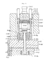
- Fig. 2 The left-hand half of Fig. 2 (i.e., Figs. 3 and 4) shows the bladder actuating mechanism A-13 during vulcanization.
- the top clamp member A-13b is fitted to a pressure receiving plate M-12 in the center of the upper half of the tire mold, and the bottom clamp member A-13c is held in the position shown in the figure by a known means against the pressure inside the tire.
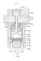
- Figs. 5 and 6 show a state where the bladder A-13a is accommodated.
- the top clamp member A-13b is placed closer to the bottom clamp member A-13c, so that both the top clamp member A-13b and the bottom clamp member A-13c are drawn into the bottom of the accommodating tube A-13d.
- the bladder A-13a which is expanded in the position shown in Fig. 3, is folded and, in this state, it is accommodated in the accommodating tube A-13d.
- the bottom clamp member A-13c is provided at proper positions thereof with a supply port and a discharge port for a heating pressure fluid supplied into and discharged from the bladder A-13a, together with pipes leading to these ports, although these elements are not illustrated.
- a plurality of mold clamping devices A-20 are mounted on the upper side of the upper bolster plate A-15 in each mold station, and driving devices C-c-1 to C-c-9 are mounted on the bolster plate C-b-2 of the mold open-close manipulator C at respective positions which face the clamping devices A-20.
- Each mold clamping device A-20 comprises a spring box A-20a, a housing A-20c slidably fitted on the spring box A-20a through a plurality of rods A-20b provided vertically on the bolster plate A-15 to extend through bores provided at proper positions in the outer peripheral portion of the housing A-20c, a plate A-20f threaded into the housing A-20c and having in its center a slide member A-20e for guiding a clamp rod A-20d, and a plurality of coned disc springs A-20g accommodated in between the plate A-20f and the spring box A-20a.
- the clamp rod A-20d is vertically movable by being guided through the slide member A-20e of the plate A-20f and a slide member A-20h provided in the spring box A-20a.
- the upper end portion of the rod A-20d has a larger diameter than that of the sliding portion thereof, and a friction plate A-20i is secured to the top surface of the rod A-20d.
- the other end portion of the rod A-20d extends through the bolster plate A-15, the heat insulating material A-16 and the heating plate A-17 and is fitted to a block M-2a that is buried in a proper portion of the outer ring M-2 of the tire mold M through thread engagement.
- Fig. 10 shows the clamp rod A-20d and the block M-2a seen from the lower end side of the rod A-20d.
- the lower end of the rod A-20d has an oval projection with such a shape that it can pass through a groove M-2b provided in the block M-2a, as shown by the one-dot chain line in the figure, and it can also be placed to intersect the groove M-2b, as shown by the solid line.
- the lower end face of the rod A-20d has a conical portion whose vertex is coincident with the axis.
- the driving devices C-c-1 to C-c-9 for the above-described connection and disconnection are mounted on the bolster plate C-b-2 of the mold open-close manipulator C. Since the manipulator C is used for a plurality of mold stations in common, the clamp driving devices C-c-1 to C-c-9 are provided on the manipulator C so as to be usable in common for the clamping devices A-20 of each mold station.
- the driving devices C-c-1 to C-c-9 are disposed on the bolster plate C-b-2 in such a manner as to face the clamping devices A-20, respectively. In other words, the number of driving devices C-c-1 to C-c-9 is the same as that of mold clamping devices A-20.
- a hydraulic cylinder c-c-1 is rigidly secured to the bolster plate C-b-2, and plate C-c-2 is secured to the rod end of the cylinder C-c-1.
- the plate C-c-2 has a plurality of guide rods C-c-3, which are guided by respective slide members C-c-4 provided in the bolster plate C-b-2.
- Below the rods C-c-3 are provided a slidable plate C-c-5 and spacers C-c-6 that limit the downward movement of the plate C-c-5.
- a spring C-c-7 is disposed between the plate C-c-2 and the plate C-c-5.
- a known rotational driving device C-c-8 such as that called “rotary cylinder” is secured to the lower side of the plate C-c-5.
- a friction plate C-c-9 is attached to the end of the output shaft of the driving device C-c-8 in such a manner as to face the friction plate A-20i of the clamping device A-20.
- the two friction plates C-c-9 and A-20i face each other across a gap, and the distal ends of the rods C-c-3 also face the housing A-20c of the clamping device A-20 across a gap without being in contact with it, as illustrated.
- the rods C-c-3 come into contact with the housing A-20c to deflect the springs A-20g, thereby releasing the clamp rod A-20d from the resilient force for abutment.
- the friction plate C-c-9 is brought into contact with the friction plate A-20i, so that the clamp rod A-20d can be rotated by the driving device C-c-8 through friction between the two friction plates that is maintained by the spring C-c-7.
- a plurality of mold clamping devices A-21 are mounted on the lower side of the lower bolster plate A-7 of each mold station.
- Each mold clamping device A-21 comprises: a spring box A-21 a; guide rods A-21 provided vertically on a housing A-21c slidably fitted on the spring box A-21 a; a housing A-21e rigidly secured to the bolster plate A-7 and having in the bottom thereof slide members A-21 for guiding the guide rods A-21 b; a hydraulic cylinder A-21f secured to the lower end of the housing A-21 e; a plate A-21 secured to the rod end of the cylinder A-21 and thread-engaged with the rods A-21 b; a plate A-21 i slidably fitted on the guide rods A-21 and limited in sliding movement by spacers A-21h; a spring A-21j disposed between the plate A-21 i and the plate A-21 g; a rotational driving device A-21 k secured to the plate A-21 i; a flange A-21 l secured to the end
- the upper end portion of the clamp rod A-21 p is arranged in the same way as in the case of the clamp rod A-20d of the clamping device A-20, while a block M-10a that is buried in the bottom plate M-10 is arranged in the same way as in the case of the block M-2a in the clamping device A-20.
- the housing A-21c is raised through the rods A-21b by a pushing-up operation of the hydraulic cylinder A-21f, causing the springs A-21m to be deflected.
- the clamp rod A-21 p is rotated by the driving device A-21 k, thereby allowing the oval projection at the distal end of the rod A-21 p to engage with or disengage from the block M-10a.
- the clamping devices C-ca are mounted on the bolster plate C-b-2 of the mold open-close manipulator C.
- the arrangement of each clamping device C-ca is the same as that of the clamping device A-21 except that these devices are in upside-down relation to each other and that a housing which is the counterpart of the housing A-21e of the clamping device A-21 is mounted on the bolster plate C-b-2 of the mold open-close manipulator C and a block A-15a that is engaged with a clamp rod is buried in the upper bolster plate A-15 by thread engagement, as shown in Figs. 13 and 14 in detail. Since the arrangement of the clamping device C-ca will readily be understood from Figs. 13 and 14 by those skilled in the art, detailed description thereof is omitted.
- the mold clamping devices A-21 are used to connect together the bottom plate M-10 and the lower bolster plate A-7 for a production operation.
- the clamping devices C-ca are held in a connected state while the manipulator C is moving between a mold station and a mold preparing station to receive and deliver a mold at the time of mold change.
- Constituent elements of each mold station which are to be movable slidably for opening and closing a mold are as follows: the upper bolster plate A-15, the upper breach lock tube A-14, the heat insulating materials A-16 and A-18, the ring A-19, the heating plate A-17, and constituent elements of the mold M, i.e., the outer ring M-2, the heat insulating material M-1, the divided segments M-3, the tread mold members M-4, the upper side mold member M-5, the ring M-7, and the top plate M-6.
- the heating plate A-17 and the outer ring M-2 need individually pipes for supplying and discharging a heating fluid that is circulated.
- each movable element is allowed to connect flexibly with a proper position of a stationary part of the press through a hose or a steel pipe through a swivel joint.
- the system herein proposed needs not only vertical movement for a production operation at each mold station but also movement from each mold station to a mold preparing station installed a long way from it for a mold changing operation and hence cannot attain the object of realizing automatic mold change with the conventional heating fluid supply and discharge method (using hoses or the like). Accordingly, the present applicant proposes arrangements described below in regard to:
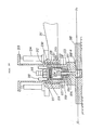
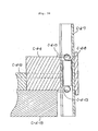
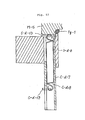
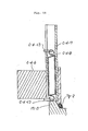
- FIGs. 15 to 20 are fragmentary views showing a mold and a mold station within a range adequate for illustration and description of the above-described heating fluid supply and discharge devices.
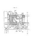
- Each mold station has a bottom pipe 101 secured to the stationary side of the mold station in such a manner as to extend vertically, the bottom pipe 101 having a flange portion 101 a with a seal member 100 buried in the upper end face thereof.
- a top pipe 102 is supported and guided by slide members 104, made of a heat insulating material, provided in a bracket 103 that is rigidly secured to a proper portion of the upper bolster plate A-15 of the mold station such that the end face of the top pipe 102 comes in and out of contact with the seal member 100.
- a projection 102a is provided on the upper portion of the top pipe 102, and a plurality of coned disc springs 106 are incorporated in between the projection 102a and a spring box 105 that is rigidly secured to the bracket 103, thereby enabling the seal member 100 and the end face of the pipe 102 to abut against each other with satisfactorily high holding force during the vulcanizing operation carried out with the mold closed.
- a hose 107a having a known joint is connected to the upper portion of the top pipe 102 that is above the spring box 105, the hose 107a being connected through a joint to a pipe 108 that is secured to the heating plate A-17 in such a manner as to extend therefrom vertically.
- hose 107a in the first set is connected to the pipe 108 for supplying a heating fluid to the heating plate A-17.
- the hose 107b in the second set is connected to a pipe 109 that is secured to the heating plate A-17 in such a manner that it extends therefrom vertically and the inner end of the pipe 109 extends as far as the bottom of the heating plate A-17, thereby being used for discharging the fluid from the circulating passage A-22 in the heating plate A-17.
- the hose 107c in the third set is connected to a pipe 115 that is communicated with an inlet port 110 for supplying the fluid to a circulating passage provided in the outer ring M-2 of the mold M.
- the hose 107d in the fourth set is connected to a pipe 116 that is communicated with an outlet port 111 for discharging the fluid from the bottom of the outer ring M-2 of the mold M.
- Piping passages for supplying and discharging the heating fluid can also be automatically formed when the top movable members of the mold station move upwardly at the time of opening the mold, and when the manipulator C moves to the first or second mold preparing station D 1 or D 2 for mold change, and also when the vulcanizing operation at the mold station is resumed after a new mold has been carried thereto by the manipulator C.
- valves (not shown) disposed at proper positions on the bottom pipe side, and after the completion of the contact between the lower end of the top pipe 102 and the seal member 100, the supply of the heating fluid is resumed by the above-described valves, as a matter of course. Since a control circuit comprising valves can readily be arranged by combining known valves, detailed description thereof is omitted.
- the outer ring M-2 of the mold M is equipped with a supply port 110 provided with a seal member 112 and a discharge port 111, which has a structure similar to that of the supply port 110 provided with the seal member 112 but is disposed at a proper position that is separate from the supply port 110.
- the lower end of the discharge port 111 extends as far as the bottom of the circulating passage in the outer ring M-2.
- a top supply pipe 115 is slidably supported by a spring box 11 rigidly secured to the upper bolster plate A-15 and slide members 114, made of a heat insulating material, which are fixedly buried in the upper bolster plate A-15, and it is biased by a plurality of coned disc springs 117 so that the inner end of the top supply pipe 115 abuts against the seal member 112 attached to the supply port 110, thus enabling the seal member 112 and the top pipe 115 to come in contact with each other firmly when the outer ring M-2 of the mold M is tightly secured to the heating plate A-17 by the mold clamping devices A-20 (see Figs. 9 and 10).
- the upper end of the top pipe 115 is connected to the above-described third device by a known hose 107 through a joint.
- the supply and discharge devices at the outer ring M-2 of the mold M are automatically disconnected. Then, the manipulator C receives a new mold at the first mold preparing station Di. At the same time as connection is made by the mold clamping devices A-20, the supply and discharge devices are also automatically connected. Further, when the mold is closed after being moved to the mold station concerned, the movable parts of the mold are automatically connected to the corresponding parts on the stationary side of the mold station.
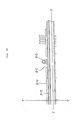
- beams B-2 are laid over the entire length of a plurality of mold stations.
- cross beams B-1 are disposed at proper positions in each mold station, and the mold stations A 1 to A12 2 and the first and second mold preparing stations D 1 and D 2 are each provided upright on the cross beams B-1.
- Each beam B-2 has a precision track member (generally known as "LM guide") B-3 rigidly secured to the top thereof.
- the track member B-3 is engaged with a bearing nut C-a-3 attached to a frame C-a-1 of the mold open-close manipulator C (described later).
- a rack B-4 (see Fig.
- the rack B-4 is in mesh with a pinion C-a-5 attached to the end of the output shaft of a rotational driving device C-a-4 rigidly provided on a truck constituting the manipulator C (see Fig. 41).
- Figs. 2 to 6 and Figs. 16 to 20 show a positioning device which is designed so that the mold open-close manipulator C is positioned accurately at each of the mold stations and the first mold preparing station Di.
- the positioning device comprises a pin C-a-8 that is vertically movable by a cylinder C-a-6 mounted on the truck of the mold open-close manipulator C, a guide bracket C-a-7 for the pin C-a-8, and pin guides B-5 that are secured to the common base frame B-2 so as to be fitted with the pin C-a-8.
- the positioning device is provided on each of the front and rear ends of the truck. The arrangement of the positioning device is shown in Figs. 17 to 20.
- the mold preparing station is disposed at each or either of the two ends of a row of mold stations or at an intermediate position of the row in such a manner as to align with the center line of the mold stations disposed in a straight line.
- the mold preparing station comprises a first station D 1 and a second station D 2 .
- the first station D 1 is used to heat and center a new mold which is to replace an old one, while the second station D 2 is used to leave a mold as it is, which is carried thereto from a mold station A by the mold open-close manipulator C for replacement.
- the first station D 1 and the second station D 2 are disposed at an intermediate position of the row of mold stations in such a way that the first and second stations D 1 and D 2 are adjacent to each other (where to dispose the first and second stations D 1 and D 2 is decided in accordance with various circumstances at each particular factory where the production system is used).
- the second station D 2 only needs a space and a support frame which are required to allow a used mold M to stand.
- the support frame is comprised only of a plurality of supports D 2 -1 of the same height which are stood on the cross beams B-1 of the common base frame B.
- Figs. 21 to 25 the second station D 2 is shown in a state where a mold M is left as it is.
- the first station D 1 comprises a bottom heating device, a top heating device, a heating fluid supply device, a loader for the top heating device, a mold centering device, a device for operating the pressure receiving plate M-12 and lifting a mold, and a positioning device for the mold open-close manipulator C.
- the bottom heating device has supports 200 of the same height which are secured to the cross beams B-1 of the common base frame B in such a manner as to extend vertically.
- the bottom heating device comprises a bottom heating plate 203 secured to the supports 200 through a heat insulating material 201 and having therein a flow passage 202 in which a heating fluid is circulated through a known pipeline, and a heat insulating material 204 attached to the outer periphery of the bottom heating plate 203.
- the upper end face of the bottom heating plate 203 is at substantially the same height as that of the bottom heating plate A-7 in each mold station A.
- the top heating device comprises a top heating plate 206 having a heating fluid circulating passage 205 therein, a heat insulating material 207, and a connecting plate 208 secured to the top heating plate 206 through the heat insulating material 207.
- the connecting plate 208 has a block 209 buried therein which is connected to and disconnected from a top heating device loader (described later).
- the top heating device is provided with heating fluid supply and discharge devices for supplying and discharging a heating fluid to and from the heating fluid passage 205 in the top heating plate 206 and the heating fluid passage M-11 in the outer ring M-2 of the mold M.
- the heating fluid supply and discharge devices have structures similar to those of the heating fluid supply and discharge devices in the mold stations A.
- the coordinate positions of the contact portions of the first to fourth heating fluid supply and discharge devices in the mold station A, shown in Figs. 21 to 25, with respect to the center of the mold station A are the same as the coordinate positions of the contact portions of the first to fourth heating fluid supply and discharge devices in the first mold preparing station D 1 with respect to the center of the first station D 1 so that when a mold M that has already been preheated and centered in the first station D 1 is moved to a mold station A with its centered state maintained, the heating fluid supply and discharge ports of the mold M are coincident with the corresponding ports in the mold station A.
- the arrangements of the heating fluid supply and discharge devices shown in Fig. 37 are so similar to those of the supply and discharge devices shown in Fig. 15 that no description is needed. Therefore, detailed description thereof is omitted.
- the top heating device loader is used to move the top heating device so that a mold lifting operation that is carried out with a forklift or the like can be conducted above the bottom heating device when the above-described heating devices receive a new mold which is to be preheated.
- the loader is also designed so as not to interfere with the movement of the mold open-close manipulator C 1 or C 2 from one mold station to another even when the top heating device is preheating a new mold from above it.
- the loader comprises a support 210 fixedly stood at a proper position out of the region where the mold open-close manipulators C 1 and C 2 pass, an arm 211 provided on the upper end of the support 210 such that the arm 211 is capable of being pivoted by a known method, a known swivel driving device (not shown), and a connecting and disconnecting device provided on the distal end of the arm 211.
- the details of the connecting and disconnecting device are shown in Figs. 29 to 32.
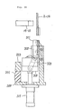
- a slide member 212 is attached to the distal end of the arm 211, and a tube 213 is slidably fitted in the slide member 212.
- the tube 231 is driven to slide by cylinders 214 stood at proper positions on the arm 211.
- a cylinder 215 is mounted at a proper position inside the tube 213.
- a plate 216 is attached to the rod end of the cylinder 215, and guide rods 218 are in thread engagement with the plate 216.
- the guide rods 218 are guided by respective slide members 217 provided in the tube 213.
- the other ends of the guide rods 218 are threaded into a block 219.
- a cover plate 220 is thread-engaged with the block 219 and has a slide member 222 provided in its center for guiding a lock shaft 221.
- a spring box 223 is disposed in the block 219, and coned disc springs 224 are accommodated in the area between the spring box 223 and the cover plate 220.
- the spring box 223 has a slide member 225 that enables the spring box 223 to be slidable in the block 219, and a slide member 226 provided in the center of the spring box 223 for guiding the lock shaft 221.
- a stopper tube 227 is provided on the side of each guide rod 218 which is closer to the block 219.
- a plate 229 is slidably fitted on the guide rods 218 through slide members 228 serving as guides, and a spring 230 is incorporated in between the plate 216 and the plate 229.
- a known crank and rocker cylinder 231 is secured to the lower side of the plate 229, and the lock shaft 221 is secured to the end of the output shaft of the cylinder 231 through flanges 232 and 233.
- the lower end portion of the lock shaft 221 is arranged in the same way as in the case of the clamp rod A-20d shown in Fig. 9 so that it can be engaged with and disengaged from a block 208-a buried in the connecting plate 208.
- the spring 230 which is provided for safety, functions in such a manner that if the oval projection at the end of the lock shaft 221 approaches the oval groove in the block 208-a in an out-of-phase state, the spring 230 is deflected to thereby protect each portion from an excessive load.
- the spring 230 is also used to sense an abnormal movement of the plate 229 with a limit switch or the like (not shown) to thereby stop the approaching operation effected by the cylinders 214.
- the loader can pivot between the central position in the first mold preparing station D 1 and the stand-by position.
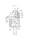
- Fig. 33 shows the mold centering device which is in a state where a mold M is lifted by a forklift or the like.
- Fig. 34 shows the mold centering device which is in a state where centering has been completed.
- Fig. 35 is a view of the mold centering device seen from the center of the mold toward the outside.
- the left-hand side of Fig. 35 corresponds to Fig. 33, while the right-hand side corresponds to Fig. 34.
- the upper half of Fig. 36 shows the mold centering device which is in the state corresponding to Fig. 33, while the lower half of Fig. 36 shows the mold centering device which is in the state corresponding to Fig. 34.
- a total of three mold centering devices are disposed as shown in Fig. 21.
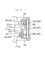
- a bracket 300 is secured to the bottom heating plate 203 through a heat insulating material 201, and isometric links 303, 304, 305 and 306 are pivotably attached to the bracket 300 through rods 301 and 302, the links being connected to a centering block 311 by pins 307, 308, 309 and 310 such that the links and the centers of the rods define a parallelogram.
- the centering block 311 has slant surfaces 311 a and 311 b on the side thereof which is closer to the center of the mold M, as shown in Fig. 36, so that the slant surfaces 311 a and 311 b can engage with slant surfaces M-10a and M-10b provided on a projecting portion of the bottom plate M-10 of the mold M (see the lower half of Fig. 36).
- the centering block 311 is connected to a plate 318 through pins 312 and 313 provided on the lower portion of the centering block 311 and through isometric links 314 and 315 and pins 316 and 317.
- the plate 318 is connected to the end of the output shaft of a cylinder 319 that is secured to the bracket 300.
- a non-oriented bearing 320 which is generally known as "free bearing" is secured to the upper side of the plate 318.
- Side portions 311 and 311 of the centering block 311 are guided by side plates 321 and 322 secured to the bracket 300 so that the centering block 311 slides accurately.
- the bottom plate M-10 of the mold M suspended by a forklift or the like is supported by the free bearing 320 in such a manner as to be movable in any direction, as shown in Fig. 33, which illustrates the mold centering device in a state where the bearing 320 is raised above the upper end face of the bottom heating plate 203.
- the centering block 311 lowers with the slant surfaces 311 a and 311 b abutting against the slant surfaces M-10a and M-10b of the bottom plate M-10, thereby centering the mold M on the bearing 320 with ease.
- the slant surfaces of the mold M abut against the corresponding slant surfaces of the three centering devices, thus completing the mold centering operation, as shown in the lower half of Fig. 36.
- the slant surfaces of the three centering devices are set at respective positions which are equidistant from the center of the first mold preparing station D 1 and the center lines of the slant surfaces are coincident with the center of the mold M, it is possible to center the mold M with high accuracy.
- This device is used in the mold preparing station D to lift and lower the pressure receiving plate M-12 in the mold M which is carried to the station D and also to raise the whole mold M to a level convenient for delivery of the mold M completely preheated at the mold preparing station D to the mold open-close manipulator C.
- Figs. 25 to 27 show a state where the upper end part of the mold clamping device is installed above the mold M and the pressure receiving plate M-12 is placed in contact with the upper side mold member M-5 which is under heating. Accordingly, the pressure receiving plate M-12 is also heated through the area of contact with the mold M.
- Fig. 28 shows a state where the loader is about to install or remove the top heating device onto or from the mold M.
- Figs. 29 to 32 show a state where the pressure receiving plate M-12 is placed in contact with the upper side mold member M-5, while the right-hand halves of these figures show a state the pressure receiving plate M-12 that is placed on the lower side mold member M-8 of the mold M is pushed to reach the state shown in the left-hand halves of the figures.
- the common base frame B is disposed in the center of the first mold preparing station Di.
- the common base frame B has a plurality of guide tubes 401 stood on a plate 400 secured to proper portions of the cross beams B-1, rods 402 that are guided by the guide tubes 401, and a lifting block 403 attached to the upper ends of the rods 402, the block 403 having a diameter larger than the inner diameter of the bottom plate M-10 of the mold M.
- the block 403 is secured to the ends of the output shafts of a plurality of hydraulic cylinders 404 stood on the plate 400 such that the block 404 is movable vertically by being guided through the rods 402 and the tubes 401.
- a pneumatic cylinder 405 is rigidly secured to the upper side of the block 403.
- a flange 406 is provided on the upper end of the output shaft of the pneumatic cylinder 405 so that when the cylinder 405 extends, the flange 406 causes the pressure receiving plate M-12 to abut against the upper side mold member M-5, whereas, when the cylinder 405 contracts, the flange 406 leaves the pressure receiving plate M-12 on the lower side mold member M-8.
- a cylinder that is the same as the air cylinder 405 is installed on the cross beams B-1, and a flange that is similar to the flange 406 is attached to the upper end of the rod of the cylinder.
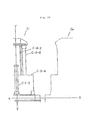
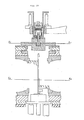
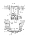
- Figs. 2 to 6 show a state where either the first mold open-close manipulator C 1 or the second mold open-close manipulator C 2 is disposed at any one of the mold stations A 1 to Ai2.
- the left-hand halves of these figures show a state where the mold operating device provided on the manipulator C is connected to the mold M in the mold station A and the mold M is closed, while the right-hand halves of the figures show a state where the mold M is opened by the manipulator C.
- Figs. 16 to 20 are front views showing the general arrangement of the manipulator C.
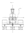
- Figs. 39 to 42 show the general arrangement of the manipulator C as seen from the direction of travel thereof.
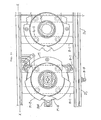
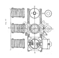
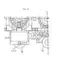
- Figs. 43 to 47 are plan views of the first manipulator C 1 and the second manipulator C 2 respectively placed at mold stations A which are adjacent to each other.
- the first manipulator C 1 is shown as seen from the arrow Q-Q in Fig. 40, while the second manipulator C 2 is shown as seen from the arrow P-P in Fig. 5.
- the second manipulator C 2 the following four positions are shown by one-dot chain lines: the first position (the center of mold station) that is reached immediately before the completed tire is removed by the unloader; the second position where the completed tire is being discharged; the third position where the completed tire is discharged; and the fourth position, which is the stand-by position assumed by the second manipulator C 2 when traveling.
- the following four positions are shown by one-dot chain lines: the first position that is reached immediately before a green tire is loaded by the loader; the second position where the green tire is being loaded; the third position where the loader is in the center of the mold; and the fourth position, which is the stand-by position assumed by the second manipulator C 2 when traveling.
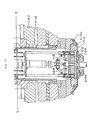
- Figs. 48 to 50 show a state where movable parts of the manipulator C are disconnected from the corresponding parts of the mold station A
- Figs. 51 to 53 show a state where the movable parts of the manipulator C are connected to the corresponding parts of the mold station A.
- the first manipulator C 1 and the second manipulator C 2 which constitute the mold open-close manipulator C, have the same arrangement and are controlled individually in operation.
- Reference symbol C-xx will be used in the following description of the arrangement of the manipulator C.
- the mold open-close manipulator C comprises a frame and travel driving device C-a, a vertical movement guide and driving device C-b, a device C-c for connection with and disconnection from the vertical movable parts in each mold station A, a bead lock mechanism C-d for installing the upper bead of a green tire on the upper bead of the mold M, a green tire loader C-e that holds a green tire and delivers it to the carcass bead loader, a green tire transfer device C-f that transfers a green tire from a green tire rest to the green tire loader C-e, and a tire unloader C-g that removes the completed tire from the tire mold M and discharges it to a known conveyor.
- the frame comprises a bottom frame C-a-1 that is designed so that it can smoothly pass the upper breach lock cylinder A-14, the lower breach lock cylinder A-4, etc. in each of the mold stations A 1 to A 12 2 which are closed to effect a vulcanizing operation when the manipulator C travels by being guided by the straight track members B-3 on the common base frame B, and a top frame C-a-2 that is designed so that the vertically movable parts can be raised and lowered with high accuracy.
- the bottom frame C-a-1 is provided with four bearings C-a-3 engaged with the straight track members B-3, a pinion C-a-5 secured to the output shaft of a rotational driving device C-a-4 secured to a proper portion of the bottom frame C-a-1, the pinion C-a-5 being in mesh with the rack B-4 provided on the common base frame B, and a lock pin C-a-8 that is vertically moved by a cylinder C-a-6 and a guide block C-a-7, which are rigidly provided in a proper portion of the bottom frame C-a-1, with respect to a positioning block disposed for each mold station A.
- the bottom frame C-a-1 is provided with the green tire loader C-e and the tire unloader C-g, as shown in Figs. 39 to 47 (the green tire loader C-e and the tire unloader C-g will be detailed later).
- the top frame C-a-2 is provided with the green tire transfer device C-f and the vertical movement guide and driving device C-b.
- the top frame C-a-2 has two parallel straight track members C-b-1 that are laid on the opposing vertical surfaces of the top frame C-a-2 in opposing relation to each other, brackets C-b-3 rigidly provided on a bolster plate C-b-2, bearings C-b-4 engaged with the track members C-b-1 and secured to the brackets C-b-3, and hydraulic cylinders C-b-5 rigidly secured at the output shaft ends thereof to the bolster plate C-b-2.
- the other ends of the hydraulic cylinders C-b-5 are secured to proper portions of the top frame C-a-2.
- a known hydraulic pressure generating device C-b-6 is provided on a proper portion of the top frame C-a-2.
- the connecting and disconnecting device C-c has the above-described members C-c-1 to C-c-9 and C-c', which are provided on the bolster plate C-b-2.
- a tube C-c-10 is secured to the center of the bolster plate C-b-2 in such a manner as to extend vertically, and a slide member C-c-11 is disposed at the lower end of the tube C-c-10, as shown in Figs. 40 and 49.
- the connecting and disconnecting device C-c further has a tube C-c-13 that is connected to the end of the output shaft of a hydraulic cylinder C-c-12 provided at the upper end of the tube C-c-10, a block C-c-14 secured to the tube C-c-13, a connecting tube C-c-15 rotatably engaged with the block C-c-14 and having on the lower end thereof intermittent teeth meshed with the intermittent teeth formed on the ring M-7 of the mold M installed in the mold station A, a circular gear C-c-16 provided on the upper end of the tube C-c-15, and a rotational driving device C-c-18 rigidly provided on a proper portion of the tube C-c-13 and having a pinion C-c-17 on the end of the output shaft thereof, the pinion C-c-17 being meshed with the gear C-c-16.
- the respective intermittent teeth of the ring M-7 and the connecting tube C-c-15 can be connected and disconnected as desired by rotating the tube C-c-15 with the driving device C-c-18 when the bolster plate C-b-2 of the manipulator C is placed in contact with the upper bolster plate A-15 of the mold station A (see Figs. 51 to 53).
- the configurations of the intermittent teeth are determined so that when these teeth are in connection with each other, force for lowering and force for raising can be transmitted to the ring M-7 from the tube C-c-15 by the operation of the hydraulic cylinder C-c-12.
- Japanese Patent Laid-Open (KOKAI) No. 02-200405 (1990) discloses a tire vulcanizer which is designed for the conventional vertical action type hydraulic press, whereas the present invention proposes an arrangement in which a bead lock mechanism is provided on the bolster plate C-b-2 of the mold open-close manipulator C so as to be usable in common for a plurality of mold stations.
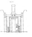
- Figs. 48 to 50 show the bead lock mechanism that is incorporated in the tube C-c-13 and the connecting tube C-c-15 of the connecting and disconnecting device.
- a lifting cylinder C-d-1 is mounted in the tube C-c-13.
- Guide rods C-d-2 guide vertical movement caused by the lifting cylinder C-d-1.
- a guide plate C-d-5 is supplied by six tie rods C-d-4 attached to a plate C-d-3 that is in turn attached to the lower ends of the lifting cylinder C-d-1 and the guide rods C-d-2.
- chucks C-d-6 are guided by the guide plate C-d-5.
- the chucks C-d-6 each having a sector C-d-7 retained thereon by a spring C-d-8 are slidable on the guide plate C-d-5.
- This sliding motion is effected by a chuck open-close cylinder C-d-9 through links C-d-12 to open or close the chucks C-d-6.
- the degree of opening of the chucks C-d-6 may be adjusted by making the chucks C-d-6 abut against the bead portion of the green tire or by adjusting the stroke of the cylinder C-d-9 by use of a known controller.
- Figs. 48 to 50 show a state where a tire vulcanizing opeation is under way, in which the bladder A-13a is disposed at the inner side of the vulcanized tire T and retained by a center post A-13f of the bladder actuating mechanism A-13, and the tire mold members M-4, M-5 and M-8 are disposed outside the vulcanized tire T.
- Fig. 54 is a sectional view seen from the arrow R-R in Fig. 50.
- each link C-d-12 is retained by guide brackets C-d-10 through a pin C-d-11.
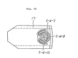
- Figs. 55 and 56 show in detail a chuck C-d-6 having a sector C-d-7 retained thereon.
- the sector C-d-7 is retained in a neutral position on the chuck C-d-6 by the spring C-d-8 attached to a pair of upper and lower spring retainers C-d-13.
- the upper bead Tg-1 of the green tire Tg that is retained by the sector C-d-7 is pushed into the top bead ring M-5 by the end of the chuck C-d-6 when pushed up by the raising force from the bead lock lifting cylinder C-d-1 with the spring C-d-8 being expanded.
- the lower bead Tg-2 of the green tire Tg is similarly inserted into the bottom bead ring M-8 by the lowering force from the bead lock lifting cylinder C-d-1.
- a lock cylinder C-d-14 is secured to the center of the guide plate C-d-5, and a guide pin C-d-15 is provided on the upper end of the cylinder C-d-1.
- the guide pin C-d-15 is engaged with a slide member C-d-17 in the center of a distal end block C-d-16 of the cylinder C-d-9, thereby guiding the distal end block C-d-16 accurately.
- the guide plate C-d-5 has a bore in the center thereof to allow a rod M-13 to pass therethrough which is stood on the center of the pressure receiving plate M-12 engaged with the mold member M-5 so that when the top clamp member A-13b of the bladder actuating mechanism A-13 is pressed upwardly by the pressure inside the bladder A-13a, the mold member M-5 bears this upward force.
- the rod M-13 is allowed to pass through the lock cylinder C-d-14 freely when a pressure fluid is supplied to the cylinder C-d-14. When the supply of the pressure fluid is cut off, the cylinder C-d-14 holds the rod M-13.
- the pressure receiving plate M-12 is engaged with the tire mold member M-5 so that the force acting on the bladder clamp member A-13b owing to the pressure inside the bladder A-13a can be born by the mold member M-5.
- the rod M-13 can pass through the lock cylinder C-d-14 freely when the bolster plate C-b-2 of the manipulator C lowers to abut against the bolster plate A-15 in the mold station A, as shown in Fig. 51.
- the lock cylinder C-d-14 holds the rod M-13, so that the rod M-13 is united with the guide plate C-d-5.
- the pressure receiving plate M-12 can be kept secured to the guide plate C-d-5.
- the chuck assembly of the bead lock device and the pressure receiving plate M-12 can be lowered below the tire mold member M-5 (see Fig. 59).
- the green tire loader C-e is mounted on the bottom frame C-a-1 of the manipulator C at the position shown in Figs. 39 to 47.
- the green tire loader C-e has three shoes C-e-1 formed to support the tread shoulder portion of the green tire Tg, and a guide plate C-e-2 having known guide grooves (not shown), with which the shoes C-e-1 are engaged.
- the guide plate C-e-2 is provided with pneumatic cylinders and shoe open-close links (not shown) so that the shoes C-e-1 can be opened and closed by the cylinders under control so as to conform to the size of a green tire received.
- a known loader basket assembly is adopted in the present invention.
- a first arm C-e-5 is pivotably attached through a pin C-e-4 to a bracket C-e-3 that is rigidly secured on the frame C-a-1
- a second arm C-e-7 is pivotably attached to the first arm C-e-5 through a pin C-e-6.
- the loader basket assembly is provided on the distal end of the second arm C-e-7.
- a cylinder C-e-8 is used to pivot the first arm C-e-5, while a cylinder C-e-9 is used to pivot the second arm C-e-7.
- the control of the four positions shown in Figs. 43 to 47 is executed by combination of extension and contraction of the two cylinders C-e-8 and C-e-9:
- the third position is coincident with the center of the mold M in the mold station A.
- the first position is coincident with the respective centers of the green tire rest E and the green tire transfer device C-f.
- the fourth position is assumed by the loader basket during the time when the manipulator C is moving between mold stations A and during the time when the green tire transfer device C-f (described later) receives a green tire from the green tire rest E and moves above the green tire loader C-e.
- the green tire transfer device C-f is rigidly provided on a proper portion of the frame C-a-2 of the manipulator C such that when the manipulator C is at rest in a mold station A, the device C-f is coincident with the center of the green tire rest E in the station A.
- the green tire transfer device C-f comprises a plurality of shoes C-f-1 each having a configuration suitable for holding the upper bead portion of the green tire Tg from the inner side thereof, a guide plate C-f-2 arranged to enable the shoes C-f-1 to expand and contract radially and synchronously, and a driving cylinders for the open-close operation, together with links, which are not shown.
- a known basket assembly is formed.
- the basket assembly is attached to the lower end of the rod of a cylinder C-f-3 vertically provided on the frame C-a-2. Accordingly, the following operation can be effected: That is, while the manipulator C is removing the tire from the mold M at a mold station A according to a predetermined procedure, the basket assembly of the transfer device C-f lowers with the shoes C-f-1 contracted so as to have a diameter smaller than the inner diameter of the bead portion of the green tire Tg on the green tire rest E, holds the green tire Tg and then moves upward with it. Thereafter, the basket assembly of the green tire loader C-e is moved from the fourth position to the first position, and subsequently the transfer device C-f lowers to install the green tire Tg on the shoes C-e-1 of the green tire loader basket assembly.
- the tire unloader C-g for the completed tire Tc is mounted on the bottom frame C-a-1 of the manipulator C at the position shown in Figs. 39 to 47.
- the unloader C-g is used to separate the completed tire Tc from the tire mold member M-8 by holding the upper bead portion of the tire Tc and moving upward, and it is also used to discharge the tire Tc onto a roller conveyor G that transfers the tire Tc to a belt conveyor F of the factory at a position outside the mold M.
- the unloader C-g comprises a plurality of shoes C-g-1 designed to be suitable for holding the tire bead portion from the inner side thereof, and a guide plate C-g-2 having known guide grooves (not shown), with which the shoes C-g-1 are engaged.
- pneumatic cylinders and shoe opening and closing links which are not shown, are provided on the guide plate C-g-2 so that the shoes C-g-1 are opened and closed by the cylinders.
- a known unloader basket assembly is adopted.
- the tire unloader C-g includes a straight track C-g-3 rigidly provided on the frame C-a-1, bearings C-g-4 engaged with the track C-g-3, a bracket C-g-5 attached to the bearings C-g-4, a hydraulic cylinder C-g-6 that enables the bracket C-g-5 to move vertically on the straight track C-g-3, a first arm C-g-8 pivotably attached to the bracket C-g-5 through a pin C-g-7, and a second arm C-g-10 pivotably attached to the first arm C-g-8 through a pin C-g-9.
- the unloader basket is secured to the distal end of the second arm C-g-10.
- the tire unloader C-g is movable between the following four positions in accordance with the combination of the two cylinders: the first position which is coincident with the center of the mold M; the second position which is assumed in the middle of the tire discharging operation; the third position which is the tire discharge position; and the fourth position which is a stand-by position for the tire unloader C-g during the time when the manipulator C is moving between mold stations A.
- the tire unloader C-g can be moved up and down by the operation of the cylinder C-g-6.
- the connecting tube C-c-15 and the ring M-6 in the mold station are connected together.
- the rod M-13 in the mold station and the lock cylinder C-d-14 are connected together.
- the heating fluid is evacuated from the bladder A-13a, and the bladder A-13a is separated from the tire and accommodated in the accommodating tube A-13d.
- the pressure cylinders A-5 are evacuated of the pressure fluid to remove the mold clamping force, resulting in a slight gap between the engaged intermittent teeth of the breach lock tubes A-4 and A-14. Thereafter, the lower breach lock tube A-4 is rotated to disengage the upper and lower intermittent teeth from each other.
- the tire unloader C-g moves upward to separate the tire from the mold member M-8 and moves to the discharge position, where the shoes C-g-1 are activated to release the tire onto the discharge conveyor G, thus completing the removal of the completed tire. Thereafter, the unloader is moved to the stand-by position. (f) During the period of time elapsed from the moment the manipulator stops at the mold station until the completed tire removing operation is started, preparations for loading of a green tire have been completed in front of the press.
- the basket assembly of the green tire transfer device C-f lowers and holds the upper bead portion of a green tire on the green tire rest E from the inner side thereof, and in this state, the basket assembly moves upward. Thereafter, the basket assembly of the green tire loader C-e is moved from the stand-by position to a position directly below the basket assembly of the transfer device C-f. Subsequently, the transfer device C-f lowers to transfer the green tire to the basket of the green tire loader C-e and then moves upward. Thus, the green tire loading preparations are completed.
- the bead lock device C-d moves upward to install the upper bead portion of the green tire to the bead mold member of the tire mold.
- the green tire loader is returned to the stand-by position from the tire mold center position.
- the bead lock device C-d executes installation of the lower bead portion.
- the manipulator lowers the bolster plate C-d-2 only for a part of the entire stroke. Since the operation that is carried out from the time when the upper bead portion is installed until the lower bead portion is installed is detailed in Japanese Patent Laid-Open (KOKAI) No. 02-200405 (1990), description thereof is herein omitted.
- the bladder A-13a is supplied with the pressure fluid, and the upper and lower bladder clamp rings A-13b and A-13c are raised to insert the bladder A-13a into the green tire.
- the bead lock device C-d is folded and accommodated such that the pressure receiving plate M-12 abuts against the upper side mold member M-5.
- the bolster plate C-b-2 of the manipulator is lowered by the cylinders C-b-5 while pressing back the cylinder C-c-12, thus closing the mold completely.
- the constituent elements are placed in the state shown in the left-hand half of Fig. 2 and Fig. 51.
- the centralized control board is instructed about a mold station which needs mold change and a designated time for replacement or a designated number of tires to be produced.
- Time at which heating of a new mold should be started is determined by calculating backward on the basis of the designated time for replacement or the replacement time calculated from the designated number of tires to be produced. Since the time required for a mold to heat up can be found in advance, it is calculated for each of various kinds of mold. Instructions are issued for the mold preparing section to prepare a mold in advance of the heating starting time calculated, and the mold preparing section carries a mold to the first mold preparing station at proper time before the heating starting time to preheat the mold until the time for replacement of the old mold.
- two manipulators may be used in such a manner that a manipulator that has been engaged in the production of the final tire at a mold station is used to close the mold and then disconnected from the mold station to move to a mold station demanding a mold open-close operation, while another manipulator moves to the mold station that needs mold change to continue the mold changing operation, in accordance with the position of the mold station needing mold change relative to the mold preparing station and in accordance with the positional relationship between the mold station needing mold change and a mold station that demands a mold open-close operation during the mold changing operation.
- the pressure receiving plate is continuously pressed against the bead ring portion during the heating process, and it is also kept pressed until the pressure receiving plate is connected to the manipulator that comes to receive the mold.
- the heating fluid is supplied to circulate through the top heating plate and the mold outer ring via the heating fluid supply and discharge devices.
- the supply of the heating fluid to the bottom heating plate is effected through a conventional fluid pipeline provided on the stationary member.
- the arm of the loader is moved from the stand-by position to the mold position to receive the top heating device. Thereafter, the arm of the loader is moved to the stand-by position.
- the process (b) in the above-described operation (3) is executed.
- the present invention provides a mold changing apparatus for use in a tire vulcanizer including a mold station having tire molds disposed in a row, a movable mold open-close manipulator, and a mold preparing station provided at a proper position in the row of tire molds for centering and preheating a tire mold, wherein the mold open-close manipulator is arranged to receive a tire mold from the mold station, to transfer it to the mold preparing station, to release it there, to receive a new mold which has already been centered and preheated at the mold preparing station, to transfer the new mold to the mold station and to install it there.
- the mold changing method it is necessary to dispose personnel for transport of a mold in accordance with the time at which the production of the final tire by a mold that should be removed from the press is completed.
- the mold may be transported when it is convenient for the mold transporting personnel.
- the mold changing operation can be executed extremely efficiently without being restricted by time.
- the present invention enables a mold to be installed in the mold preparing station only by the forklift or crane operator. Further, it is possible to lower by a large margin the costs of equipment related to loading and unloading in the tire vulcanizer and hence possible to reduce the overall cost of equipment of the tire vulcanizer.
Landscapes
- Engineering & Computer Science (AREA)
- Mechanical Engineering (AREA)
- Robotics (AREA)
- Physics & Mathematics (AREA)
- Health & Medical Sciences (AREA)
- Oral & Maxillofacial Surgery (AREA)
- Thermal Sciences (AREA)
- Moulds For Moulding Plastics Or The Like (AREA)
- Heating, Cooling, Or Curing Plastics Or The Like In General (AREA)
- Tyre Moulding (AREA)
Applications Claiming Priority (2)
| Application Number | Priority Date | Filing Date | Title |
|---|---|---|---|
| JP3092165A JP2686375B2 (ja) | 1991-04-23 | 1991-04-23 | タイヤ製造装置 |
| JP92165/91 | 1991-04-23 |
Publications (3)
| Publication Number | Publication Date |
|---|---|
| EP0510332A2 true EP0510332A2 (fr) | 1992-10-28 |
| EP0510332A3 EP0510332A3 (en) | 1993-12-08 |
| EP0510332B1 EP0510332B1 (fr) | 1998-05-06 |
Family
ID=14046818
Family Applications (1)
| Application Number | Title | Priority Date | Filing Date |
|---|---|---|---|
| EP92103471A Expired - Lifetime EP0510332B1 (fr) | 1991-04-23 | 1992-02-28 | Dispositif pour changer les moules dans une machine de vulcanisation de pneus |
Country Status (5)
| Country | Link |
|---|---|
| US (1) | US5271727A (fr) |
| EP (1) | EP0510332B1 (fr) |
| JP (1) | JP2686375B2 (fr) |
| KR (1) | KR960002222B1 (fr) |
| DE (1) | DE69225351T2 (fr) |
Cited By (7)
| Publication number | Priority date | Publication date | Assignee | Title |
|---|---|---|---|---|
| WO1999025542A1 (fr) * | 1997-11-14 | 1999-05-27 | The Goodyear Tire And Rubber Company | Systeme et procede de vulcanisation |
| WO2000066336A1 (fr) | 1999-04-30 | 2000-11-09 | Mitsubishi Heavy Industries, Ltd. | Installation de vulcanisation de pneus, ouverture/fermeture de cette installation, et postes de vulcanisation |
| EP1002632A3 (fr) * | 1998-11-20 | 2000-11-29 | Mitsubishi Heavy Industries, Ltd. | Appareil de vulcanisation de pneus. |
| US6610238B1 (en) | 1997-11-14 | 2003-08-26 | The Goodyear Tire And Rubber Company | Tire curing system and method |
| CN103286894A (zh) * | 2013-06-13 | 2013-09-11 | 慈溪市鸿时捷橡胶制品有限公司 | 一种橡胶件生产自动化设备 |
| CN110871535A (zh) * | 2018-09-03 | 2020-03-10 | 钜钢机械股份有限公司 | 直线多模站成型加工机械的模具交换机构 |
| CN111469449A (zh) * | 2020-04-08 | 2020-07-31 | 北京天域科技有限公司 | 一种模压多机联动自动化生产线 |
Families Citing this family (21)
| Publication number | Priority date | Publication date | Assignee | Title |
|---|---|---|---|---|
| JP3450027B2 (ja) * | 1993-05-07 | 2003-09-22 | 株式会社神戸製鋼所 | タイヤ加硫機における型交換台車 |
| US5820885A (en) * | 1993-09-14 | 1998-10-13 | Mitsubishi, Jukogyo Kabushiki Kaisha | Tire vulcanizing system |
| JPH0857858A (ja) * | 1994-08-25 | 1996-03-05 | Kobe Steel Ltd | タイヤ加硫システム |
| EP0712704A3 (fr) * | 1994-11-16 | 1996-11-13 | Mitsubishi Heavy Ind Ltd | Assemblage de moule de vulcanisation de pneumatiques |
| JP3219643B2 (ja) * | 1994-11-18 | 2001-10-15 | 三菱重工業株式会社 | タイヤ金型運搬装置 |
| JP3637156B2 (ja) * | 1996-07-29 | 2005-04-13 | 三菱重工業株式会社 | タイヤ加硫機 |
| US5773041A (en) * | 1997-06-11 | 1998-06-30 | Mcneil & Nrm, Inc. | Mold clamping system |
| US6086811A (en) * | 1998-04-29 | 2000-07-11 | The Goodyear Tire & Rubber Company | Molding system for rubber tractor tracks |
| US6177042B1 (en) * | 1998-11-23 | 2001-01-23 | The Goodyear Tire & Rubber Company | Method and apparatus for making integral rubber tractor tracks |
| AU1919199A (en) * | 1998-12-16 | 2000-07-03 | Goodyear Tire And Rubber Company, The | Automated green tire conveyance system |
| US6051178A (en) * | 1999-02-19 | 2000-04-18 | Goodyear Tire & Rubber Company | Method and apparatus for making an endless rubber tractor track |
| JP4909040B2 (ja) * | 2006-12-13 | 2012-04-04 | 三菱重工業株式会社 | タイヤ加硫設備及びタイヤ加硫方法 |
| JP4473907B2 (ja) * | 2007-12-12 | 2010-06-02 | 株式会社神戸製鋼所 | ポストキュアインフレータおよびそのリム交換方法並びにリム |
| FR2951401B1 (fr) * | 2009-10-20 | 2016-12-30 | Soc De Tech Michelin | Presse de vulcanisation |
| DE102014001644A1 (de) * | 2013-02-26 | 2014-08-28 | Harburg-Freudenberger Maschinenbau Gmbh | Vorrichtung zum Vorheizen von mindestens einer Form |
| US10779838B1 (en) | 2013-11-13 | 2020-09-22 | Joseph W Blake, III | Instrument for serially applying clips to a surgical site |
| US10098641B1 (en) | 2014-08-21 | 2018-10-16 | Joseph W Blake, III | Jaws and cams for clip applying instruments |
| US9968363B2 (en) | 2014-10-20 | 2018-05-15 | Joseph W. Blake, III | Multi-clip applier |
| DE102016003071A1 (de) | 2015-05-28 | 2016-12-01 | Harburg-Freudenberger Maschinenbau Gmbh | Schließkrafteinheit |
| CN109622774A (zh) * | 2018-12-26 | 2019-04-16 | 无锡新瑞驰科技有限公司 | 一种模具头更换装置 |
| CN114274439B (zh) * | 2022-03-07 | 2022-07-05 | 成都航利航空科技有限责任公司 | 基于智造单元的橡胶产品三维布局生产架构及生产方法 |
Family Cites Families (10)
| Publication number | Priority date | Publication date | Assignee | Title |
|---|---|---|---|---|
| US3550196A (en) * | 1967-01-30 | 1970-12-29 | Nrm Corp | Tire vulcanizing apparatus |
| US3783241A (en) * | 1971-06-03 | 1974-01-01 | B E Goodrich Co | Apparatus for heat conditioning of green tires for vulcanization |
| US3918861A (en) * | 1974-10-11 | 1975-11-11 | Cooper Tire & Rubber Co | Vulcanizing press with rotary locking mechanism |
| US3932079A (en) * | 1975-01-29 | 1976-01-13 | Valery Leonidovich Legostaev | Pneumatic tire vulcanizing apparatus |
| US4025251A (en) * | 1975-11-06 | 1977-05-24 | Nrm Corporation | Vulcanizer lock means |
| JPS5970536A (ja) * | 1982-10-15 | 1984-04-21 | Mitsubishi Heavy Ind Ltd | タイヤ加硫機の金型交換装置 |
| JPH0237844B2 (ja) * | 1982-10-15 | 1990-08-28 | Mitsubishi Heavy Ind Ltd | Taiyakaryukinokanagatakokanhoho |
| IT1176523B (it) * | 1984-08-01 | 1987-08-18 | Pirelli | Perfezionamenti nelle presse per la vulcanizzazione |
| US4880792A (en) * | 1986-11-06 | 1989-11-14 | Mazda Motor Corporation | Molding installation using die |
| IT1198210B (it) * | 1986-12-01 | 1988-12-21 | Pirelli | Stampo per pneumatici e dispositivo automatico per lo smontaggio rapido dalla relativa pressa |
-
1991
- 1991-04-23 JP JP3092165A patent/JP2686375B2/ja not_active Expired - Fee Related
-
1992
- 1992-02-28 EP EP92103471A patent/EP0510332B1/fr not_active Expired - Lifetime
- 1992-02-28 DE DE69225351T patent/DE69225351T2/de not_active Expired - Lifetime
- 1992-04-22 US US07/871,985 patent/US5271727A/en not_active Expired - Lifetime
- 1992-04-23 KR KR1019920006868A patent/KR960002222B1/ko not_active Expired - Lifetime
Cited By (11)
| Publication number | Priority date | Publication date | Assignee | Title |
|---|---|---|---|---|
| WO1999025542A1 (fr) * | 1997-11-14 | 1999-05-27 | The Goodyear Tire And Rubber Company | Systeme et procede de vulcanisation |
| US6610238B1 (en) | 1997-11-14 | 2003-08-26 | The Goodyear Tire And Rubber Company | Tire curing system and method |
| EP1002632A3 (fr) * | 1998-11-20 | 2000-11-29 | Mitsubishi Heavy Industries, Ltd. | Appareil de vulcanisation de pneus. |
| US6338620B1 (en) | 1998-11-20 | 2002-01-15 | Mitsubishi Heavy Industries, Ltd. | Tire-vulcanizing machine |
| WO2000066336A1 (fr) | 1999-04-30 | 2000-11-09 | Mitsubishi Heavy Industries, Ltd. | Installation de vulcanisation de pneus, ouverture/fermeture de cette installation, et postes de vulcanisation |
| EP1125708A4 (fr) * | 1999-04-30 | 2002-07-10 | Mitsubishi Heavy Ind Ltd | Installation de vulcanisation de pneus, ouverture/fermeture de cette installation, et postes de vulcanisation |
| US6547548B1 (en) | 1999-04-30 | 2003-04-15 | Mitsubishi Heavy Industries, Ltd. | Tire vulcanizing system and mold opening/closing and vulcanizing station therefor |
| EP1477295A1 (fr) * | 1999-04-30 | 2004-11-17 | Mitsubishi Heavy Industries, Ltd. | Système de vulcanisation de pneus, ouverture/fermeture de ce système, et poste de vulcanisation |
| CN103286894A (zh) * | 2013-06-13 | 2013-09-11 | 慈溪市鸿时捷橡胶制品有限公司 | 一种橡胶件生产自动化设备 |
| CN110871535A (zh) * | 2018-09-03 | 2020-03-10 | 钜钢机械股份有限公司 | 直线多模站成型加工机械的模具交换机构 |
| CN111469449A (zh) * | 2020-04-08 | 2020-07-31 | 北京天域科技有限公司 | 一种模压多机联动自动化生产线 |
Also Published As
| Publication number | Publication date |
|---|---|
| KR920019524A (ko) | 1992-11-19 |
| JP2686375B2 (ja) | 1997-12-08 |
| EP0510332A3 (en) | 1993-12-08 |
| DE69225351T2 (de) | 1998-10-15 |
| JPH04323010A (ja) | 1992-11-12 |
| EP0510332B1 (fr) | 1998-05-06 |
| US5271727A (en) | 1993-12-21 |
| DE69225351D1 (de) | 1998-06-10 |
| KR960002222B1 (ko) | 1996-02-13 |
Similar Documents
| Publication | Publication Date | Title |
|---|---|---|
| EP0510332B1 (fr) | Dispositif pour changer les moules dans une machine de vulcanisation de pneus | |
| US6113833A (en) | Segmented toroidal core for manufacturing pneumatic tires | |
| EP1568475B1 (fr) | Systeme de moulage de pneumatiques et procede de fabrication d'un pneumatique en utilisant ce systeme | |
| KR0168510B1 (ko) | 타이어 가황장치 | |
| US7281916B2 (en) | Tire vulcanizing system and tire manufacturing method to be used therefor | |
| SK144295A3 (en) | Tyre moulds transporting device | |
| JP3798545B2 (ja) | タイヤ加硫設備 | |
| EP0955153B1 (fr) | Appareil de vulcanisation de pneus avec moule à secteurs | |
| EP0712704A2 (fr) | Assemblage de moule de vulcanisation de pneumatiques | |
| EP1477295B1 (fr) | Station d' ouverture/fermeture d'une forme et de vulcanisation de pneus | |
| JP4623884B2 (ja) | タイヤの製造方法および加硫システム | |
| US6461134B1 (en) | Mold exchanger system for tire vulcanizing machine | |
| JP3009567B2 (ja) | タイヤ加硫設備 | |
| JP4119576B2 (ja) | タイヤ加硫設備 | |
| EP1092530A2 (fr) | Installation de vulcanisation de pneumatiques | |
| JPH0929746A (ja) | タイヤ加硫用金型組立体 | |
| JP3181180B2 (ja) | タイヤ加硫設備 | |
| JP4623892B2 (ja) | タイヤ加硫システム | |
| JP2003053731A (ja) | タイヤ加硫システム | |
| JP4623882B2 (ja) | タイヤ加硫システム | |
| JPH08323768A (ja) | タイヤ金型運搬装置 | |
| JP2001322126A (ja) | タイヤ加硫機の中心機構 |
Legal Events
| Date | Code | Title | Description |
|---|---|---|---|
| PUAI | Public reference made under article 153(3) epc to a published international application that has entered the european phase |
Free format text: ORIGINAL CODE: 0009012 |
|
| 17P | Request for examination filed |
Effective date: 19920325 |
|
| AK | Designated contracting states |
Kind code of ref document: A2 Designated state(s): DE FR GB |
|
| PUAL | Search report despatched |
Free format text: ORIGINAL CODE: 0009013 |
|
| RHK1 | Main classification (correction) |
Ipc: B29C 33/04 |
|
| AK | Designated contracting states |
Kind code of ref document: A3 Designated state(s): DE FR GB |
|
| 17Q | First examination report despatched |
Effective date: 19950915 |
|
| GRAG | Despatch of communication of intention to grant |
Free format text: ORIGINAL CODE: EPIDOS AGRA |
|
| GRAG | Despatch of communication of intention to grant |
Free format text: ORIGINAL CODE: EPIDOS AGRA |
|
| GRAH | Despatch of communication of intention to grant a patent |
Free format text: ORIGINAL CODE: EPIDOS IGRA |
|
| GRAH | Despatch of communication of intention to grant a patent |
Free format text: ORIGINAL CODE: EPIDOS IGRA |
|
| GRAA | (expected) grant |
Free format text: ORIGINAL CODE: 0009210 |
|
| AK | Designated contracting states |
Kind code of ref document: B1 Designated state(s): DE FR GB |
|
| REF | Corresponds to: |
Ref document number: 69225351 Country of ref document: DE Date of ref document: 19980610 |
|
| ET | Fr: translation filed | ||
| PLBE | No opposition filed within time limit |
Free format text: ORIGINAL CODE: 0009261 |
|
| STAA | Information on the status of an ep patent application or granted ep patent |
Free format text: STATUS: NO OPPOSITION FILED WITHIN TIME LIMIT |
|
| 26N | No opposition filed | ||
| REG | Reference to a national code |
Ref country code: GB Ref legal event code: IF02 |
|
| PGFP | Annual fee paid to national office [announced via postgrant information from national office to epo] |
Ref country code: DE Payment date: 20110223 Year of fee payment: 20 Ref country code: FR Payment date: 20110218 Year of fee payment: 20 |
|
| PGFP | Annual fee paid to national office [announced via postgrant information from national office to epo] |
Ref country code: GB Payment date: 20110223 Year of fee payment: 20 |
|
| REG | Reference to a national code |
Ref country code: DE Ref legal event code: R071 Ref document number: 69225351 Country of ref document: DE |
|
| REG | Reference to a national code |
Ref country code: DE Ref legal event code: R071 Ref document number: 69225351 Country of ref document: DE |
|
| REG | Reference to a national code |
Ref country code: GB Ref legal event code: PE20 Expiry date: 20120227 |
|
| PG25 | Lapsed in a contracting state [announced via postgrant information from national office to epo] |
Ref country code: DE Free format text: LAPSE BECAUSE OF EXPIRATION OF PROTECTION Effective date: 20120229 |
|
| PG25 | Lapsed in a contracting state [announced via postgrant information from national office to epo] |
Ref country code: GB Free format text: LAPSE BECAUSE OF EXPIRATION OF PROTECTION Effective date: 20120227 |