EP0510342B1 - Trockner für Teigwaren - Google Patents
Trockner für Teigwaren Download PDFInfo
- Publication number
- EP0510342B1 EP0510342B1 EP92104139A EP92104139A EP0510342B1 EP 0510342 B1 EP0510342 B1 EP 0510342B1 EP 92104139 A EP92104139 A EP 92104139A EP 92104139 A EP92104139 A EP 92104139A EP 0510342 B1 EP0510342 B1 EP 0510342B1
- Authority
- EP
- European Patent Office
- Prior art keywords
- pasta
- chamber
- conveyor
- drier according
- drying
- Prior art date
- Legal status (The legal status is an assumption and is not a legal conclusion. Google has not performed a legal analysis and makes no representation as to the accuracy of the status listed.)
- Expired - Lifetime
Links
Images





Classifications
-
- F—MECHANICAL ENGINEERING; LIGHTING; HEATING; WEAPONS; BLASTING
- F26—DRYING
- F26B—DRYING SOLID MATERIALS OR OBJECTS BY REMOVING LIQUID THEREFROM
- F26B15/00—Machines or apparatus for drying objects with progressive movement; Machines or apparatus with progressive movement for drying batches of material in compact form
- F26B15/10—Machines or apparatus for drying objects with progressive movement; Machines or apparatus with progressive movement for drying batches of material in compact form with movement in a path composed of one or more straight lines, e.g. compound, the movement being in alternate horizontal and vertical directions
- F26B15/12—Machines or apparatus for drying objects with progressive movement; Machines or apparatus with progressive movement for drying batches of material in compact form with movement in a path composed of one or more straight lines, e.g. compound, the movement being in alternate horizontal and vertical directions the lines being all horizontal or slightly inclined
- F26B15/14—Machines or apparatus for drying objects with progressive movement; Machines or apparatus with progressive movement for drying batches of material in compact form with movement in a path composed of one or more straight lines, e.g. compound, the movement being in alternate horizontal and vertical directions the lines being all horizontal or slightly inclined the objects or batches of materials being carried by trays or racks or receptacles, which may be connected to endless chains or belts
- F26B15/143—Machines or apparatus for drying objects with progressive movement; Machines or apparatus with progressive movement for drying batches of material in compact form with movement in a path composed of one or more straight lines, e.g. compound, the movement being in alternate horizontal and vertical directions the lines being all horizontal or slightly inclined the objects or batches of materials being carried by trays or racks or receptacles, which may be connected to endless chains or belts the receptacles being wholly or partly foraminous, e.g. containing a batch of loose material
-
- F—MECHANICAL ENGINEERING; LIGHTING; HEATING; WEAPONS; BLASTING
- F26—DRYING
- F26B—DRYING SOLID MATERIALS OR OBJECTS BY REMOVING LIQUID THEREFROM
- F26B15/00—Machines or apparatus for drying objects with progressive movement; Machines or apparatus with progressive movement for drying batches of material in compact form
- F26B15/10—Machines or apparatus for drying objects with progressive movement; Machines or apparatus with progressive movement for drying batches of material in compact form with movement in a path composed of one or more straight lines, e.g. compound, the movement being in alternate horizontal and vertical directions
-
- F—MECHANICAL ENGINEERING; LIGHTING; HEATING; WEAPONS; BLASTING
- F26—DRYING
- F26B—DRYING SOLID MATERIALS OR OBJECTS BY REMOVING LIQUID THEREFROM
- F26B15/00—Machines or apparatus for drying objects with progressive movement; Machines or apparatus with progressive movement for drying batches of material in compact form
- F26B15/10—Machines or apparatus for drying objects with progressive movement; Machines or apparatus with progressive movement for drying batches of material in compact form with movement in a path composed of one or more straight lines, e.g. compound, the movement being in alternate horizontal and vertical directions
- F26B15/20—Machines or apparatus for drying objects with progressive movement; Machines or apparatus with progressive movement for drying batches of material in compact form with movement in a path composed of one or more straight lines, e.g. compound, the movement being in alternate horizontal and vertical directions the lines being all vertical or steeply inclined
- F26B15/22—Machines or apparatus for drying objects with progressive movement; Machines or apparatus with progressive movement for drying batches of material in compact form with movement in a path composed of one or more straight lines, e.g. compound, the movement being in alternate horizontal and vertical directions the lines being all vertical or steeply inclined the objects or batches of materials being carried by endless belts the objects or batches of material being carried by trays or holders supported by endless belts or chains
-
- F—MECHANICAL ENGINEERING; LIGHTING; HEATING; WEAPONS; BLASTING
- F26—DRYING
- F26B—DRYING SOLID MATERIALS OR OBJECTS BY REMOVING LIQUID THEREFROM
- F26B25/00—Details of general application not covered by group F26B21/00 or F26B23/00
- F26B25/001—Handling, e.g. loading or unloading arrangements
-
- F—MECHANICAL ENGINEERING; LIGHTING; HEATING; WEAPONS; BLASTING
- F26—DRYING
- F26B—DRYING SOLID MATERIALS OR OBJECTS BY REMOVING LIQUID THEREFROM
- F26B25/00—Details of general application not covered by group F26B21/00 or F26B23/00
- F26B25/008—Seals, locks, e.g. gas barriers or air curtains, for drying enclosures
-
- F—MECHANICAL ENGINEERING; LIGHTING; HEATING; WEAPONS; BLASTING
- F26—DRYING
- F26B—DRYING SOLID MATERIALS OR OBJECTS BY REMOVING LIQUID THEREFROM
- F26B2210/00—Drying processes and machines for solid objects characterised by the specific requirements of the drying goods
- F26B2210/08—Short pasta, e.g. macaroni, vermicelli
-
- Y—GENERAL TAGGING OF NEW TECHNOLOGICAL DEVELOPMENTS; GENERAL TAGGING OF CROSS-SECTIONAL TECHNOLOGIES SPANNING OVER SEVERAL SECTIONS OF THE IPC; TECHNICAL SUBJECTS COVERED BY FORMER USPC CROSS-REFERENCE ART COLLECTIONS [XRACs] AND DIGESTS
- Y10—TECHNICAL SUBJECTS COVERED BY FORMER USPC
- Y10S—TECHNICAL SUBJECTS COVERED BY FORMER USPC CROSS-REFERENCE ART COLLECTIONS [XRACs] AND DIGESTS
- Y10S198/00—Conveyors: power-driven
- Y10S198/952—Heating or cooling
Definitions
- the present invention relates to a drier for pasta a disclosed in the preamble of independent claim 1 (see EP-A-0 195 394 ).
- dry pasta generally means pasta with a water content of between 11.5 and 12.5% by weight.
- the ability to withstand cooking is correlated to a known parameter called the cooking factor.
- This parameter takes account of the chewability, palatability, consistency and organoleptic characteristics of the pasta after cooking.
- the pasta must have good chewing strength (it should not be hard or stick to the teeth) but should have the consistency typical of so-called "al dente" pasta, it should be slippery and flexible in the dish, and it should not develop a patina which makes its surface sticky or glutinous.
- Another important factor associated with the drying method is constituted by the danger of the nutritive properties (in particular the essential aminoacids) of the pasta being degraded by heat, the extent of this degradation being considered by many to depend on the drying temperature and period.
- the best known is carried out entirely at a low temperature within the range of between 40° and 60°C.
- the organoleptic and nutritive qualities of the dry pasta thus produced remain almost unaltered but, according to some critics, it has high acidity and a poor cooking factor which adversely affect its commercial qualities.
- EP-A-0 195 394 describes a drier which allows to dry pasta in a shorter time, comprising a pre-heater, a first and a second drying chamber with pasta-holders which are transported from the pre-heater to the drying chambers by a conveyor mechanism.
- EP-A-0 195 394 does not disclose means for hermetically closing and opening inlet and outlet ports of the different chambers.
- Another equally widespread method which was established in order to overcome the long periods of time (of the order of 16-24 hours) required to carry out the method mentioned above and to reduce the considerable lengths of the driers needed as a result, provides for treatment at very high temperatures of up to 110-120°C. Whilst this method of treatment can drastically reduce the dimensions of the driers, the nutritional and organoleptic properties of the durum wheat semolina used cannot always be kept intact since they may be altered substantially by the high temperatures which, in particular, cause thermal degradation of the essential aminoacids in the dry pasta produced.
- the drying is carried out in a plurality of successive isothermal heat-treatment stages, with a gradual increase of the temperature within the range of from 40° to 110°C.
- the present invention is based on the problem of devising and providing a drier for pasta which has structural and functional characteristics such that it can completely satisfy the requirements of any drying method and any variant thereof by means of a few quick and easy alterations of those characteristics.
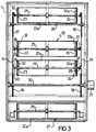
- a pasta drier includes a plurality of structurally independent drying chambers (four in the embodiment shown) 1, 2, 3 and 4 aligned and spaced apart on a base 5.
- the drying chambers are all the same and are all similarly equipped, that is to say, they are modular chambers and, in the following description, reference will therefore be made to only one chamber unless otherwise stated.
- Each drying chamber (1 to 4) contains conventional means, not shown, for regulating, controlling and monitoring all the parameters which affect the pasta-drying process, particularly the temperature, the relative humidity, the pressure, etc., as well as devices, shown schematically, for admitting steam, air and anything else required to achieve and maintain climatic-ambient conditions determined beforehand in dependence on a preferred pasta-drying curve.
- each chamber (1 to 4) is a pasta-inlet port 6 and a pasta-outlet port 7 which can be closed hermetically by respective pairs of gates 8, 9 and 10, 11 operated, for example, by respective pneumatic cylinders 12 and 12a.
- the vertical conveyor 13 is preferably constituted by two parallel, spaced-apart chains 14, 15 supported and driven by respective sprockets 16, 17 and 18, 19.
- the sprockets 16 and 18 are keyed to the same shaft 20 which extends in correspondence with the pasta-inlet and outlet ports 6 and 7 and is driven by a motor 21 supported outside the drying chamber in question.
- Containers or holders 22 for the pasta to be treated in the drying chambers are connected removably to corresponding links of the opposed chains 14, 15.
- the containers 22 are constituted essentially by baskets, preferably cylindrical baskets, for holding predetermined modest quantities of pasta to be dried. They are permeable to air and steam (Fig. 4) and, for this purpose, each preferably has a cylindrical wall 22a of netting fixed at opposite ends to the peripheries of discs 23,24 keyed to a shaft 25 coaxial with its cylindrical wall. Outwardly of the discs 23 and 24, the shaft 25 defines two opposed hubs 26, 27 by means of which the container 22 is connected to the opposed chains 14, 15 of the vertical conveyor 13.
- a pin 28 projects from each of corresponding links of the opposed chains 14, 15 and the upper end of a rod-like support 29 (a hanger), whose other end 31 is substantially cradle-shaped with a semicylindrical base 30, is rotatable thereon.
- the cylindrical hubs 26, 27 are supported in the cradles 31 of the supports 29 of the opposed chains 14, 15.
- Respective sprockets 32 and 32a are keyed to the hubs 26 and 27 of each container 22 for engaging respective rod-like racks 33 supported vertically near the chains 14, 15.
- each container 22 rotates about its own axis whilst it is transported within the drying chamber by the chains 14, 15.
- cylindrical wall of the container 22 has a hole 34 with a door 35, also preferably of netting, for loading the pasta into the container and unloading it therefrom.
- the drying chambers (1 to 3) are connected to each other by respective tunnels 36 (or air-tight chambers).
- tunnels 36 or air-tight chambers.
- there are three tunnels 36 which, to advantage, are all the same and are all similarly equipped, that is to say, they are modular elements.
- Each tunnel 36 is fixed releasably to two adjacent drying chambers (1-2; 2-3; 3-4) in correspondence with their respective outlet and inlet ports 7 and 6 in a pressurised-fluid-tight manner by known means, not shown, and is separated therefrom by the gates 10, 11 and 8, 9 which can thus also be considered as tunnel-inlet and tunnel-outlet gates respectively.
- the pneumatic cylinders 12, 12a for operating the gates are installed in the tunnels 36.
- the tunnels may have their own gates operated independently of those of the chambers.
- a device, generally indicated 37, is disposed in each tunnel 36 for transferring a container 22 from one drying chamber to the next, as will become clear from the following description.
- the device 37 preferably comprises a trolley 38 slidable on horizontal guides 39, 40 extending from the tunnel-inlet gates 8, 9 to the tunnel-outlet gates 10, 11.
- the trolley is driven by conventional drive means represented schematically by a pair of chains 41, 41 and, on its upper part has two horizontal arms 42, 43 spaced apart by a distance at least equal to the length of a cylindrical basket 22.
- Cradle-shaped supports are fixed to the opposite ends of the arms 42 and 43 for receiving the hubs 26 and 27 of a cylindrical basket 22.
- the arms 42, 43 are of a length such that, when the trolley 38 reaches the end of its travel near the outlet door of a drying chamber (for example, the chamber 1), their ends with their cradle-shaped supports 44 are beside (Fig. 4) the descending passes of the chains 14, 15 of the conveyor 13 and interfere with the downward path of the supports 29 thereof whilst, when the trolley is at the end of its travel near the inlet door of the next drying chamber (for example, the chamber 2), their ends and their cradle-shaped supports 45 are beside the ascending passes of the chains 14, 15 of the conveyor 13 of that chamber, interfering with the upward paths of the supports 29.
- a conventional weighing station 47 also installed in each tunnel 36 comprises a pair of hydraulic cylinders 48, 49 with vertical axes spaced from the arms 42, 43 of the trolley 38. Respective cradle-shaped supports 50, 51 are fixed to the rods 48a, 49a of the hydraulic cylinders for engaging the hubs 26, 27 of a cylindrical basket 22.
- Respective transfer devices 52, 53 just like the device 37 described above are positioned and operative at the inlet side and the outlet side of the first and last drying chambers (1, 4) of the drier of the invention to supply the pasta to be dried thereto and discharge the dried pasta therefrom, as will become clear from the following description.
- the transfer devices 52 and 53 operate in respective tunnels 52a, 53a which are closed to the exterior by pairs of pneumatically-operated gates 60, 61.
- a tunnel 54 extends longitudinally through the base beneath the plurality of drying chambers 1 to 4.
- a conveyor, generally indicated 55, disposed in the tunnel 54 is preferably of the type constituted by a pair of parallel chains just like the chains used for the conveyors 13 in the individual drying chambers 1 to 4.
- the conveyor 55 extends from a pasta-loading station 58 upstream of the transfer device 52 to a dried-pasta discharge station 59 downstream of the transfer device 53.
- the conveyor 55 is used for returning the containers or holders 22 (in particular, for example, the cylindrical baskets 22) from the dried-pasta discharge station to the station for the loading of fresh pasta to be dried.
- the drier of the invention operates as follows.
- a drier according to the invention is formed by assembling that number of drying chambers, in each of which ambient conditions exactly corresponding to one of the operating stages is created.
- the containers are taken from the station 58 one after another by the transfer device 52 on the input side of the drier and transferred to the ascending pass of the conveyor 13 of the drying chamber 1 (or first chamber).
- the transfer device 52 on the input side of the drier and transferred to the ascending pass of the conveyor 13 of the drying chamber 1 (or first chamber).
- the containers of fresh pasta remain in the first drying chamber for a predetermined "staying period" during which they are circulated through the chamber continuously and, in the case of the cylindrical baskets described above, are rotated about their own axes.
- the pasta is thus treated as uniformly as possible. Only when the predetermined time for which a container remains in the first drying chamber has fully elapsed is the container removed by the transfer device 37 in the first tunnel 36 and carried to the ascending pass of the conveyor 13 in the second drying chamber (the chamber 2).
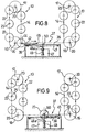
- the trolley 38 is brought to the end of its travel near the outlet port 7 of the drying chamber 1. In this position, the cradle-shaped supports 44 of the arms 42 are engaged by the hubs 26, 27 of the container 22 in question. As soon as the container is disengaged from the cradles 31 of the hangers 29, the trolley 38 is moved along the tunnel 36 to a position such that the hubs 26 and 27 of the container 20 transported thereby are aligned vertically with the cradle-shaped supports 50, 51 of the hydraulic cylinders 48 and 49 of the weighing station 47.
- the container 22 Whilst the gates 10, 11 are closed, the container 22 is lifted and simultaneously weighed by the operation of the hydraulic cylinders 48 and 49.
- the trolley 38 returns to the drying chamber 1 and stops in a position such that its cradle-shaped supports 45 (Fig. 10) are aligned vertically with the hubs 26, 27 of the container 22.
- the cylinders 48, 49 are lowered again until the container 22 is taken over by the cradle-shaped supports 45 of the trolley 38.
- the trolley 38 is moved to the end of its travel near the inlet door 6 to the drying chamber 2 (Fig. 11). In this position, the container 22 is placed in the path of the ascending passes of the chains 14, 15 of the conveyor 13 of this chamber and is picked up thereby.
- the trolley 38 re-enters into the tunnel 36 where, after the gates 8, 9 are closed, it returns to its starting position ready for the next transfer operation.
- the dried pasta is discharged from the containers at the station 59 and the containers are quickly sent back to the loading station 58 by the chain conveyor 55 through the tunnel 54 in the base 5 of the drier.
- the drier also affords many other advantages.
- a distinct improvement has been achieved in the quality of the finished product due to a large extent to the fact that the drying curve for the product can be divided up and the thermal stress controlled, thus substantially attentuating the reduction in the nutritional quality of the treated pasta.
- a further advantage is constituted by rapid adaptability to the optimum conditions for each form of pasta.
- the containers or holders for the pasta to be dried may differ from the cylindrical baskets described by way of example.
- the supports may be conventional rods for supporting spaghetti, conveyor belts or the like.
Landscapes
- Engineering & Computer Science (AREA)
- Mechanical Engineering (AREA)
- General Engineering & Computer Science (AREA)
- Drying Of Solid Materials (AREA)
- Noodles (AREA)
- Manufacturing And Processing Devices For Dough (AREA)
- Addition Polymer Or Copolymer, Post-Treatments, Or Chemical Modifications (AREA)
- Intermediate Stations On Conveyors (AREA)
- Specific Conveyance Elements (AREA)
- Inorganic Insulating Materials (AREA)
Claims (12)
- Trockner für Teigwaren, mit- mehreren konstruktiv unabhängigen Trockenkammern (1 bis 4), die jeweils ihre eigenen herkömmlichen Einrichtungen zur unabhängigen Erzeugung, Regulierung und Überwachung vorgegebener klimatischer Raumbedingungen sowie eine Teigwaren-Einlaßöffnung (6) und eine Teigwaren-Auslaßöffnung (7) aufweisen,- einem endlosen Teigwarenförderer (13), der sich in jeder Trockenkammer (1 bis 4) erstreckt und an einer Position angeordnet ist, an der er durch die Teigwaren-Einlaßöffnung (6) und die Teigwaren-Auslaßöffnung (7) zugänglich ist,- mehreren entfernbaren Teigwarenbehältern (22) am Förderer (13),- mehreren Gängen (36), die die Trockenkammern (1 bis 4) miteinander verbinden, wobei jeder der Gänge (36) zwei aufeinanderfolgende, benachbarte Kammern (1 - 2, 2 - 3, 3 - 4) verbindet und sich von der Teigwaren-Auslaßöffnung (7) einer Kammer zur Teigwaren-Einlaßöffnung (6) der nächsten Kammer erstreckt,
dadurch gekennzeichnet,
daß der Trockner weiterhin umfaßt- unabhängig voneinander arbeitende Mittel zum hermetischen Schließen und Öffnen der Öffnungen (6, 7) sowie- eine in jedem der Gänge (36) angebrachte Transporteinrichtung (37), die einen Teigwarenbehälter (22) aus dem Förderer (13) einer Trockenkammer (1, 2, 3) entnimmt und auf den Förderer (13) der nächsten, benachbarten Trockenkammer (2, 3, 4) lädt. - Trockner nach Anspruch 1, dadurch gekennzeichnet, daß die Mittel zum hermetischen Schließen und Öffnen der Teigwaren-Einlaßöffnung (6) und der Teigwaren-Auslaßöffnung (7) Verschlußpaare (8, 9; 10, 11) umfassen, die unabhängig voneinander betätigt werden.
- Trockner nach Anspruch 2, dadurch gekennzeichnet, daß jedes der Verschlußpaare (8, 9; 10, 11) von zwei Druckluftzylindern (12, 12a) betätigt wird.
- Trockner nach Anspruch 1, dadurch gekennzeichnet, daß der Förderer (13) zwei mit Abstand angeordnete vertikale Ketten (14, 15) umfaßt, die von zugehörigen Kettenrädern (16, 17, 18, 19) gehalten und angetrieben werden, und daß die Teigwarenbehälter zylindrische Behälter (22) mit luft- und dampfdurchlässigen zylindrischen Wänden (22a) sind und in an den Ketten (14, 15) angebrachten, einander gegenüberliegenden wiegenartigen Stützen (29) entfernbar eingehängt werden.
- Trockner nach Anspruch 1, dadurch gekennzeichnet, daß jeder der Gänge (36) mit zwei benachbarten Trockenkammern (1-2,2 - 3, 3 - 4) an deren Teigwaren-Einlaßöffnung (6) bzw. Teigwaren-Auslaßöffnung (7) dergestalt entfernbar verbunden ist, daß der Gasdruck aufrechterhalten bleibt.
- Trockner nach Anspruch 3, dadurch gekennzeichnet, daß die Druckluftzylinder (12, 12a) zur Betätigung der Verschlußpaare (8, 9; 10, 11) in den Gängen (36) angebracht sind.
- Trockner nach Anspruch 4, dadurch gekennzeichnet, daß die Transporteinrichtung (37) einen Schlitten (38) umfaßt, der auf Führungen (39, 40) verschiebbar ist, die sich von der Teigwaren-Auslaßöffnung (7) einer Trockenkammer (1, 2, 3) zur Teigwaren-Einlaßöffnung (6) der nächsten Trockenkammer (2, 3, 4) erstrecken, und auf der Oberseite zu den Führungen (39, 40) parallele Arme (42, 43) mit wiegenartigen Stützen (44, 45) zum Halten der zylindrischen Behälter (22) an deren entgegengesetzten Enden aufweist.
- Trockner nach Anspruch 7, dadurch gekennzeichnet, daß der Schlitten (38) auf den Führungen (39, 40) bewegbar ist zwischen einer ersten Position, an der die Stützen (44) an einem Ende der Arme (42, 43) in die Bahn der sich nach unten bewegenden Stützen (29), die an den Ketten (14, 15) einer Trockenkammer (1, 2, 3) angebracht sind, gelangen, und einer zweiten Position, an der die Stützen (45) am anderen Ende der Arme (42, 43) in die Bahn der sich nach oben bewegenden Stützen (29), die an den Ketten (14, 15) der nächsten Trockenkammer (2, 3, 4) angebracht sind, gelangen, wobei der Schlitten (38) außerdem mindestens an einer sich zwischen der ersten und der zweiten Position befindenden dritten Position angehalten werden kann.
- Trockner nach Anspruch 1, dadurch gekennzeichnet, daß er in jedem der Gänge (36) eine Wiegestation (47) zum Wiegen eines Behälters (22) umfaßt.
- Trockner nach Anspruch 9, dadurch gekennzeichnet, daß die Wiegestation (47) an der dritten Halteposition des Schlittens (38) arbeitet.
- Trockner nach Anspruch 1, dadurch gekennzeichnet, daß er eine weitere Transporteinrichtung (52) umfaßt, die an der Einlaßöffnung (6) der ersten Trockenkammer (1) angeordnet ist und in diese einen Behälter (22) einführt und auf den Förderer (13) der ersten Kammer lädt.
- Trockner nach Anspruch 1, dadurch gekennzeichnet, daß er eine weitere Transporteinrichtung (53) umfaßt, die an der Auslaßöffnung (7) der letzten Trockenkammer (4) angeordnet ist und vom Förderer (13) dieser Kammer einen Behälter (22) ablädt und von dort abtransportiert.
Applications Claiming Priority (2)
| Application Number | Priority Date | Filing Date | Title |
|---|---|---|---|
| ITMI911114 | 1991-04-23 | ||
| ITMI911114A IT1246974B (it) | 1991-04-23 | 1991-04-23 | Essiccatoio per pasta alimentare |
Publications (2)
| Publication Number | Publication Date |
|---|---|
| EP0510342A1 EP0510342A1 (de) | 1992-10-28 |
| EP0510342B1 true EP0510342B1 (de) | 1996-05-29 |
Family
ID=11359739
Family Applications (1)
| Application Number | Title | Priority Date | Filing Date |
|---|---|---|---|
| EP92104139A Expired - Lifetime EP0510342B1 (de) | 1991-04-23 | 1992-03-11 | Trockner für Teigwaren |
Country Status (11)
| Country | Link |
|---|---|
| US (1) | US5184542A (de) |
| EP (1) | EP0510342B1 (de) |
| JP (1) | JPH07115738B2 (de) |
| AT (1) | ATE138731T1 (de) |
| AU (1) | AU638890B2 (de) |
| CA (1) | CA2063659C (de) |
| DE (1) | DE69211051T2 (de) |
| DK (1) | DK0510342T3 (de) |
| ES (1) | ES2088039T3 (de) |
| GR (1) | GR3020793T3 (de) |
| IT (1) | IT1246974B (de) |
Families Citing this family (8)
| Publication number | Priority date | Publication date | Assignee | Title |
|---|---|---|---|---|
| FR2795937B1 (fr) * | 1999-07-09 | 2001-09-14 | Air Liquide | Machine de croutage en ligne |
| EP1098154B1 (de) * | 1999-11-03 | 2002-10-16 | Food Machinery Espanola S.A. | Tunnel zur Trocknung von Obst und Gemüse |
| JP4782811B2 (ja) * | 2008-06-09 | 2011-09-28 | 株式会社新井機械製作所 | 菓子類の製造方法並びにその製造装置 |
| ITPR20080059A1 (it) * | 2008-09-26 | 2010-03-27 | Imas S P A | Procedimento ed apparato per l essiccazione di prodotti ceramici |
| DE102009014020A1 (de) * | 2009-03-23 | 2010-09-30 | Bühler AG | Verfahren und Vorrichtung zum Trocknen von Gütern |
| CN104359294A (zh) * | 2014-11-21 | 2015-02-18 | 信阳凯米特环保工程有限公司 | 膨胀珍珠岩保温板烘干系统 |
| US10834944B2 (en) * | 2016-09-14 | 2020-11-17 | Allpax Products Llc | Retort load/unload system and method |
| ES2684054B1 (es) * | 2017-03-28 | 2019-07-29 | Corporacion Omegazeta S L | Horno para el fraguado de paneles de mortero de cemento e instalación correspondiente |
Family Cites Families (22)
| Publication number | Priority date | Publication date | Assignee | Title |
|---|---|---|---|---|
| DE293416C (de) * | ||||
| US1391939A (en) * | 1919-11-20 | 1921-09-27 | Charles W Collins | Ventilating appliance for clothes-drying machines |
| US1498774A (en) * | 1922-02-09 | 1924-06-24 | U S Bobbin & Shuttle Company | Drying machine |
| US1539976A (en) * | 1923-09-18 | 1925-06-02 | Vernaci Joseph | Macaroni drier |
| US1839628A (en) * | 1929-09-11 | 1932-01-05 | Francis C Williams | Barrel steamer and drier |
| US1891873A (en) * | 1930-06-10 | 1932-12-20 | Elbe Rudolf | Apparatus for treating food stuffs such as meat and fish |
| US2632378A (en) * | 1945-08-20 | 1953-03-24 | Carvallo Pierre | Can cooker |
| NL82451C (de) * | 1948-04-19 | |||
| US2583847A (en) * | 1948-11-22 | 1952-01-29 | Buehler Ag Geb | Continuous-type spaghetti drier |
| FR1027391A (fr) * | 1950-09-09 | 1953-05-11 | Machine pour assurer le séchage des pâtes alimentaires dites longues | |
| US2988819A (en) * | 1956-10-24 | 1961-06-20 | Buehler Ag Geb | Method for drying macaroni products |
| US3165055A (en) * | 1959-05-02 | 1965-01-12 | Stork & Co Nv | Apparatus for the continuous sterilization or pasteurization of foodstuffs packed incontainers |
| US3202115A (en) * | 1961-08-21 | 1965-08-24 | Baker Perkins Inc | Pusher type transfer apparatus for baking ovens and the like |
| US3323227A (en) * | 1963-03-18 | 1967-06-06 | Bassano Joseph | Drying apparatus for macaroni and the like |
| US3268055A (en) * | 1963-08-24 | 1966-08-23 | Stein Karl | Drying device for the soles of shoes |
| DE1429984B2 (de) * | 1964-01-04 | 1971-11-04 | F. Küppersbusch & Söhne AG, 4650 Gelsenkirchen | Bratautomat |
| US3258103A (en) * | 1964-01-31 | 1966-06-28 | Francisci Machine Corp De | Continuous drier apparatus |
| DE2702247A1 (de) * | 1977-01-20 | 1978-07-27 | Ventilazione Italiana Sas | Vertikaler trockenofen |
| CH635042A5 (de) * | 1979-02-15 | 1983-03-15 | Buehler Ag Geb | Verfahren zum herstellen von verkaufsfertigen teigwarenportionenverpackungen. |
| US4538363A (en) * | 1984-02-01 | 1985-09-03 | Zagoroff Dimiter S | Shrink oven |
| IT1188509B (it) * | 1985-03-21 | 1988-01-14 | Mario Pavan | Macchina perfezionata per l'essiccazione ad alta temperatura di paste alimentari o prodotti similari |
| IT1234383B (it) * | 1989-02-02 | 1992-05-15 | Patrizio Fazion | Impianto di essiccamento per paste alimentari o prodotti similari. |
-
1991
- 1991-04-23 IT ITMI911114A patent/IT1246974B/it active IP Right Grant
-
1992
- 1992-03-11 ES ES92104139T patent/ES2088039T3/es not_active Expired - Lifetime
- 1992-03-11 AT AT92104139T patent/ATE138731T1/de not_active IP Right Cessation
- 1992-03-11 DK DK92104139.8T patent/DK0510342T3/da active
- 1992-03-11 DE DE69211051T patent/DE69211051T2/de not_active Expired - Fee Related
- 1992-03-11 EP EP92104139A patent/EP0510342B1/de not_active Expired - Lifetime
- 1992-03-16 AU AU12883/92A patent/AU638890B2/en not_active Ceased
- 1992-03-20 CA CA002063659A patent/CA2063659C/en not_active Expired - Fee Related
- 1992-04-03 JP JP4082150A patent/JPH07115738B2/ja not_active Expired - Lifetime
- 1992-04-23 US US07/872,328 patent/US5184542A/en not_active Expired - Fee Related
-
1996
- 1996-08-14 GR GR960402173T patent/GR3020793T3/el unknown
Also Published As
| Publication number | Publication date |
|---|---|
| ES2088039T3 (es) | 1996-08-01 |
| ATE138731T1 (de) | 1996-06-15 |
| CA2063659A1 (en) | 1992-10-24 |
| DK0510342T3 (da) | 1996-10-14 |
| GR3020793T3 (en) | 1996-11-30 |
| ITMI911114A0 (it) | 1991-04-23 |
| IT1246974B (it) | 1994-12-01 |
| DE69211051T2 (de) | 1996-11-21 |
| EP0510342A1 (de) | 1992-10-28 |
| JPH069038A (ja) | 1994-01-18 |
| DE69211051D1 (de) | 1996-07-04 |
| JPH07115738B2 (ja) | 1995-12-13 |
| US5184542A (en) | 1993-02-09 |
| CA2063659C (en) | 1994-09-20 |
| ITMI911114A1 (it) | 1992-10-23 |
| AU638890B2 (en) | 1993-07-08 |
| AU1288392A (en) | 1992-10-29 |
Similar Documents
| Publication | Publication Date | Title |
|---|---|---|
| US6442866B2 (en) | Method and apparatus for drying or heat-treating products | |
| CN104769377B (zh) | 有机材料的微波真空干燥 | |
| US5184542A (en) | Drier for pasta | |
| US2583847A (en) | Continuous-type spaghetti drier | |
| US5523053A (en) | Sterilization method and apparatus for spices and herbs | |
| JP3752621B2 (ja) | ソーセージを製造する方法および処理すべきソーセージを収納するコンテナ | |
| US4790335A (en) | Tobacco curer | |
| EP0541896B1 (de) | Fördergerät zum Transportieren von Lasagne und ähnlichen Formen von Teigwaren durch einen Trockner | |
| US3864846A (en) | Automated steaming apparatus | |
| US5860356A (en) | System for production of sterile-packed rice | |
| KR101102816B1 (ko) | 굴 건조장치 및 방법 | |
| JP2676561B2 (ja) | パスタ等の製品の乾燥装置 | |
| KR101893742B1 (ko) | 곡물 가공용 증자기 | |
| KR200395889Y1 (ko) | 터널 수하식 농산물 건조장치 | |
| KR101030181B1 (ko) | 유과 제조장치 및 제조방법 | |
| US2833095A (en) | Packing | |
| JP3414010B2 (ja) | パック食品の加熱調理方法及びその装置 | |
| JP4770372B2 (ja) | 無菌パック米飯の製造方法及びその装置 | |
| AU640084B2 (en) | A conveyor for transporting lasagne and similar forms of pasta through a drier | |
| CN216775985U (zh) | 一种发芽糯稻保湿干燥装置 | |
| CZ276097A3 (cs) | Způsob zpracování šarží potravin zráním a zařízení k provádění tohoto způsobu | |
| WO1999044432A1 (en) | Method and apparatus for food processing | |
| JP2025059122A (ja) | 麺線群の蒸煮・搬送装置及び蒸煮方法 | |
| HK1208524B (en) | Microwave vacuum-drying of organic materials | |
| ITMI940948A1 (it) | Procedimento per la produzione in continuo di un prodotti alimentare granulare a base di amido, cotto ed espanso |
Legal Events
| Date | Code | Title | Description |
|---|---|---|---|
| PUAI | Public reference made under article 153(3) epc to a published international application that has entered the european phase |
Free format text: ORIGINAL CODE: 0009012 |
|
| AK | Designated contracting states |
Kind code of ref document: A1 Designated state(s): AT BE CH DE DK ES FR GB GR IT LI LU MC NL PT SE |
|
| 17P | Request for examination filed |
Effective date: 19920827 |
|
| RAP1 | Party data changed (applicant data changed or rights of an application transferred) |
Owner name: BARILLA G. E R. F.LLI - SOCIETA PER AZIONI |
|
| RAP3 | Party data changed (applicant data changed or rights of an application transferred) |
Owner name: BARILLA G. E R. F.LLI - SOCIETA PER AZIONI |
|
| 17Q | First examination report despatched |
Effective date: 19930916 |
|
| GRAH | Despatch of communication of intention to grant a patent |
Free format text: ORIGINAL CODE: EPIDOS IGRA |
|
| GRAA | (expected) grant |
Free format text: ORIGINAL CODE: 0009210 |
|
| AK | Designated contracting states |
Kind code of ref document: B1 Designated state(s): AT BE CH DE DK ES FR GB GR IT LI LU MC NL PT SE |
|
| REF | Corresponds to: |
Ref document number: 138731 Country of ref document: AT Date of ref document: 19960615 Kind code of ref document: T |
|
| ITF | It: translation for a ep patent filed | ||
| REG | Reference to a national code |
Ref country code: CH Ref legal event code: NV Representative=s name: JACOBACCI & PERANI S.A. |
|
| ET | Fr: translation filed | ||
| REG | Reference to a national code |
Ref country code: ES Ref legal event code: BA2A Ref document number: 2088039 Country of ref document: ES Kind code of ref document: T3 |
|
| REF | Corresponds to: |
Ref document number: 69211051 Country of ref document: DE Date of ref document: 19960704 |
|
| REG | Reference to a national code |
Ref country code: ES Ref legal event code: FG2A Ref document number: 2088039 Country of ref document: ES Kind code of ref document: T3 |
|
| SC4A | Pt: translation is available |
Free format text: 960530 AVAILABILITY OF NATIONAL TRANSLATION |
|
| REG | Reference to a national code |
Ref country code: DK Ref legal event code: T3 |
|
| REG | Reference to a national code |
Ref country code: GR Ref legal event code: FG4A Free format text: 3020793 |
|
| PLBE | No opposition filed within time limit |
Free format text: ORIGINAL CODE: 0009261 |
|
| STAA | Information on the status of an ep patent application or granted ep patent |
Free format text: STATUS: NO OPPOSITION FILED WITHIN TIME LIMIT |
|
| 26N | No opposition filed | ||
| REG | Reference to a national code |
Ref country code: GB Ref legal event code: IF02 |
|
| PGFP | Annual fee paid to national office [announced via postgrant information from national office to epo] |
Ref country code: AT Payment date: 20050221 Year of fee payment: 14 |
|
| PGFP | Annual fee paid to national office [announced via postgrant information from national office to epo] |
Ref country code: NL Payment date: 20050222 Year of fee payment: 14 Ref country code: MC Payment date: 20050222 Year of fee payment: 14 |
|
| PGFP | Annual fee paid to national office [announced via postgrant information from national office to epo] |
Ref country code: SE Payment date: 20050223 Year of fee payment: 14 Ref country code: PT Payment date: 20050223 Year of fee payment: 14 Ref country code: DK Payment date: 20050223 Year of fee payment: 14 |
|
| PGFP | Annual fee paid to national office [announced via postgrant information from national office to epo] |
Ref country code: LU Payment date: 20050224 Year of fee payment: 14 Ref country code: GR Payment date: 20050224 Year of fee payment: 14 Ref country code: CH Payment date: 20050224 Year of fee payment: 14 |
|
| PGFP | Annual fee paid to national office [announced via postgrant information from national office to epo] |
Ref country code: GB Payment date: 20050225 Year of fee payment: 14 Ref country code: DE Payment date: 20050225 Year of fee payment: 14 |
|
| PGFP | Annual fee paid to national office [announced via postgrant information from national office to epo] |
Ref country code: BE Payment date: 20050301 Year of fee payment: 14 |
|
| PGFP | Annual fee paid to national office [announced via postgrant information from national office to epo] |
Ref country code: ES Payment date: 20050308 Year of fee payment: 14 |
|
| PGFP | Annual fee paid to national office [announced via postgrant information from national office to epo] |
Ref country code: FR Payment date: 20050325 Year of fee payment: 14 |
|
| PG25 | Lapsed in a contracting state [announced via postgrant information from national office to epo] |
Ref country code: GB Free format text: LAPSE BECAUSE OF NON-PAYMENT OF DUE FEES Effective date: 20060311 Ref country code: AT Free format text: LAPSE BECAUSE OF NON-PAYMENT OF DUE FEES Effective date: 20060311 |
|
| PG25 | Lapsed in a contracting state [announced via postgrant information from national office to epo] |
Ref country code: SE Free format text: LAPSE BECAUSE OF NON-PAYMENT OF DUE FEES Effective date: 20060312 |
|
| PG25 | Lapsed in a contracting state [announced via postgrant information from national office to epo] |
Ref country code: ES Free format text: LAPSE BECAUSE OF NON-PAYMENT OF DUE FEES Effective date: 20060313 |
|
| PG25 | Lapsed in a contracting state [announced via postgrant information from national office to epo] |
Ref country code: MC Free format text: LAPSE BECAUSE OF NON-PAYMENT OF DUE FEES Effective date: 20060331 Ref country code: LU Free format text: LAPSE BECAUSE OF NON-PAYMENT OF DUE FEES Effective date: 20060331 Ref country code: LI Free format text: LAPSE BECAUSE OF NON-PAYMENT OF DUE FEES Effective date: 20060331 Ref country code: DK Free format text: LAPSE BECAUSE OF NON-PAYMENT OF DUE FEES Effective date: 20060331 Ref country code: CH Free format text: LAPSE BECAUSE OF NON-PAYMENT OF DUE FEES Effective date: 20060331 Ref country code: BE Free format text: LAPSE BECAUSE OF NON-PAYMENT OF DUE FEES Effective date: 20060331 |
|
| PGFP | Annual fee paid to national office [announced via postgrant information from national office to epo] |
Ref country code: IT Payment date: 20060331 Year of fee payment: 15 |
|
| PG25 | Lapsed in a contracting state [announced via postgrant information from national office to epo] |
Ref country code: PT Free format text: LAPSE BECAUSE OF NON-PAYMENT OF DUE FEES Effective date: 20060911 |
|
| PG25 | Lapsed in a contracting state [announced via postgrant information from national office to epo] |
Ref country code: NL Free format text: LAPSE BECAUSE OF NON-PAYMENT OF DUE FEES Effective date: 20061001 |
|
| PG25 | Lapsed in a contracting state [announced via postgrant information from national office to epo] |
Ref country code: DE Free format text: LAPSE BECAUSE OF NON-PAYMENT OF DUE FEES Effective date: 20061003 |
|
| REG | Reference to a national code |
Ref country code: DK Ref legal event code: EBP |
|
| REG | Reference to a national code |
Ref country code: PT Ref legal event code: MM4A Effective date: 20060911 |
|
| REG | Reference to a national code |
Ref country code: CH Ref legal event code: PL |
|
| EUG | Se: european patent has lapsed | ||
| GBPC | Gb: european patent ceased through non-payment of renewal fee |
Effective date: 20060311 |
|
| NLV4 | Nl: lapsed or anulled due to non-payment of the annual fee |
Effective date: 20061001 |
|
| REG | Reference to a national code |
Ref country code: FR Ref legal event code: ST Effective date: 20061130 |
|
| REG | Reference to a national code |
Ref country code: ES Ref legal event code: FD2A Effective date: 20060313 |
|
| BERE | Be: lapsed |
Owner name: *BARILLA G. E R. F.LLI - S.P.A. Effective date: 20060331 |
|
| PG25 | Lapsed in a contracting state [announced via postgrant information from national office to epo] |
Ref country code: FR Free format text: LAPSE BECAUSE OF NON-PAYMENT OF DUE FEES Effective date: 20060331 |
|
| PG25 | Lapsed in a contracting state [announced via postgrant information from national office to epo] |
Ref country code: GR Free format text: LAPSE BECAUSE OF NON-PAYMENT OF DUE FEES Effective date: 20061002 |
|
| PG25 | Lapsed in a contracting state [announced via postgrant information from national office to epo] |
Ref country code: IT Free format text: LAPSE BECAUSE OF NON-PAYMENT OF DUE FEES Effective date: 20070311 |