EP0510351A2 - Outil d'enfoncement d'attaches - Google Patents
Outil d'enfoncement d'attaches Download PDFInfo
- Publication number
- EP0510351A2 EP0510351A2 EP92104549A EP92104549A EP0510351A2 EP 0510351 A2 EP0510351 A2 EP 0510351A2 EP 92104549 A EP92104549 A EP 92104549A EP 92104549 A EP92104549 A EP 92104549A EP 0510351 A2 EP0510351 A2 EP 0510351A2
- Authority
- EP
- European Patent Office
- Prior art keywords
- slide
- driving tool
- guide rail
- magazine
- jacket
- Prior art date
- Legal status (The legal status is an assumption and is not a legal conclusion. Google has not performed a legal analysis and makes no representation as to the accuracy of the status listed.)
- Granted
Links
- 238000010304 firing Methods 0.000 claims abstract description 28
- 239000002184 metal Substances 0.000 claims abstract description 8
- 239000000463 material Substances 0.000 abstract description 5
- 238000003780 insertion Methods 0.000 abstract description 2
- 230000037431 insertion Effects 0.000 abstract description 2
- 238000004519 manufacturing process Methods 0.000 description 6
- 238000000034 method Methods 0.000 description 4
- 238000013461 design Methods 0.000 description 3
- 230000007257 malfunction Effects 0.000 description 3
- 239000003795 chemical substances by application Substances 0.000 description 2
- 230000001419 dependent effect Effects 0.000 description 2
- 238000007373 indentation Methods 0.000 description 2
- 239000002023 wood Substances 0.000 description 2
- 229910000831 Steel Inorganic materials 0.000 description 1
- 239000000853 adhesive Substances 0.000 description 1
- 230000001070 adhesive effect Effects 0.000 description 1
- 239000011324 bead Substances 0.000 description 1
- 238000005452 bending Methods 0.000 description 1
- 230000015572 biosynthetic process Effects 0.000 description 1
- 239000002131 composite material Substances 0.000 description 1
- 238000011161 development Methods 0.000 description 1
- 230000018109 developmental process Effects 0.000 description 1
- 230000008030 elimination Effects 0.000 description 1
- 238000003379 elimination reaction Methods 0.000 description 1
- 239000004744 fabric Substances 0.000 description 1
- 239000011888 foil Substances 0.000 description 1
- 238000001746 injection moulding Methods 0.000 description 1
- 238000003754 machining Methods 0.000 description 1
- 238000004806 packaging method and process Methods 0.000 description 1
- 230000002093 peripheral effect Effects 0.000 description 1
- 238000003825 pressing Methods 0.000 description 1
- 238000012545 processing Methods 0.000 description 1
- 230000035939 shock Effects 0.000 description 1
- 239000007787 solid Substances 0.000 description 1
- 239000010959 steel Substances 0.000 description 1
- -1 upholstery Substances 0.000 description 1
- 238000003466 welding Methods 0.000 description 1
Images




Classifications
-
- B—PERFORMING OPERATIONS; TRANSPORTING
- B25—HAND TOOLS; PORTABLE POWER-DRIVEN TOOLS; MANIPULATORS
- B25C—HAND-HELD NAILING OR STAPLING TOOLS; MANUALLY OPERATED PORTABLE STAPLING TOOLS
- B25C5/00—Manually operated portable stapling tools; Hand-held power-operated stapling tools; Staple feeding devices therefor
- B25C5/16—Staple-feeding devices, e.g. with feeding means, supports for staples or accessories concerning feeding devices
- B25C5/1696—Staple support displaceable relative to the tool to allow re-loading
-
- B—PERFORMING OPERATIONS; TRANSPORTING
- B25—HAND TOOLS; PORTABLE POWER-DRIVEN TOOLS; MANIPULATORS
- B25C—HAND-HELD NAILING OR STAPLING TOOLS; MANUALLY OPERATED PORTABLE STAPLING TOOLS
- B25C5/00—Manually operated portable stapling tools; Hand-held power-operated stapling tools; Staple feeding devices therefor
- B25C5/16—Staple-feeding devices, e.g. with feeding means, supports for staples or accessories concerning feeding devices
- B25C5/1637—Supports for the staples being fed
- B25C5/1641—Supports for the staples being fed allowing the feeding of a variety of elements
- B25C5/1644—Supports for the staples being fed allowing the feeding of a variety of elements of different shapes
- B25C5/1651—Supports for the staples being fed allowing the feeding of a variety of elements of different shapes of T-shaped staples or nails
-
- B—PERFORMING OPERATIONS; TRANSPORTING
- B25—HAND TOOLS; PORTABLE POWER-DRIVEN TOOLS; MANIPULATORS
- B25C—HAND-HELD NAILING OR STAPLING TOOLS; MANUALLY OPERATED PORTABLE STAPLING TOOLS
- B25C5/00—Manually operated portable stapling tools; Hand-held power-operated stapling tools; Staple feeding devices therefor
- B25C5/16—Staple-feeding devices, e.g. with feeding means, supports for staples or accessories concerning feeding devices
- B25C5/1637—Supports for the staples being fed
- B25C5/1641—Supports for the staples being fed allowing the feeding of a variety of elements
- B25C5/1658—Supports for the staples being fed allowing the feeding of a variety of elements of different sizes of staples
Definitions
- the invention is based on a driving tool according to the preamble of claim 1.
- Such devices are very susceptible to malfunctions in the event of insufficient dimensional accuracy or wear of the firing channel. It is easy for staples to jam.
- the devices therefore require a high degree of dimensional accuracy and manufacturing precision and usually only allow the use of a certain type of tack in the same shot channel.
- From DE-PS 35 00 279 a generic wrapping device is known, with which two slightly different U-shaped staple types can be processed in their back width.
- the magazine cannot be used for narrow and long staples made of stronger wire or for nails.
- the device has a mouth that is too short for use in inaccessible places.
- the driving tool according to the invention with the characterizing features of claim 1 has the advantage that it is user-friendly and universally applicable and at the same time high Functional reliability guaranteed. In particular, it is also easily possible to look up stapling materials that have not been fully driven in. In addition, the precise manufacture of the magazine in particular is simple and easy to assemble.
- the device enables easy filling of the magazine with staples of very different widths and with nails. Wide brackets are more suitable for fastening foils, upholstery, fabrics etc. and for furniture. Long, narrow staples with thicker wire are preferred for panels, ceilings, profiled wood and packaging wood.
- a one-piece curved tacking slide according to claim 7 simplifies manufacture and assembly.
- a one-sided from the outside movable bar according to claim 8 serves as an insertion aid for narrow brackets and as a lateral guide for nails and pens.
- the arrangement of a tension spring leads to a pressing force on the tacking means which remains largely independent of the filling level of the magazine.
- a end plate or scraper plate profiled according to the dimensions of the stapling means prevents malfunctions due to inclined or jammed stapling means in the firing channel; this applies in particular to narrow brackets.
- the detachable end plate has the further advantage that the magazine is easy to manufacture, assemble and service.
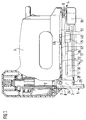
- FIG. 1 shows a partially sectioned overall view of a driving tool and FIG. 2 shows a longitudinal section through a magazine
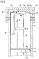
- FIG. 3 shows a cross section through the magazine according to line III in FIG. 2
- FIG. 4 shows a stripping plate as a detail
- FIG. 5 shows a cross section according to line V in FIG. 2
- FIG. 6 shows a longitudinal section through the firing channel.
- Figure 7 shows a view of an end plate.
- a driving tool has in a housing 1 a shock knife 2, which is driven in particular by a current-carrying coil and is guided in a firing channel 3.
- the firing channel 3 extends into a magazine 4 and ends in a land-stretched mouth 5.
- the magazine 4 is mounted at the front near the firing channel 3 in an elongated hole 7, which is penetrated by a pin 8 fixed to the housing, with limited vertical movement.
- the magazine 4 is connected to the housing 1 so that it can rotate about a horizontal axis 9.
- the magazine 4 consists essentially of a U-shaped, downwardly open jacket 11 and a slider 12 engaging therein, which will be described later with reference to FIG. 3.
- the jacket 11 has in one of its flanks 13 a longitudinal slot 14 which is penetrated by a handle 15.
- the handle 15 is connected to a bar 16 which is displaceable within the casing 11.
- the strip 16 constricts the interior of the magazine 4 in a partial area and can be designed as a sheet metal part or as a plastic-steel composite part.
- the upper middle part 17 of the casing 11, which connects the flanks 13, has a narrow slot 18.
- the magazine 4 has latching locking parts 19 (not shown in more detail) for fixing the slide 12.
- the magazine 4 is delimited by a U-shaped jacket end 21 attached to the flanks of the jacket 11 and encompassing the firing channel 3.
- the jacket end 21 forms a quiver running in the direction of the firing channel 3 for inserting an end plate 22 in which the stapling means 23 to be processed are guided. This will be described in more detail later with reference to FIG. 5.
- the end plate is held by a spring clip 24.
- a retaining pin 25 is fastened to the spring clip 24 or beads or tabs are formed on the spring clip 24, which engage in a recess 26 on the end plate 22 (cf. FIG. 2).
- the spring clip 24 is hooked onto the jacket end 21.
- Support flaps 28 are bent away from the jacket face 21 below the flanks and engage around the slide 12 and fix it in its vertical position (see FIG. 1).
- the slide 12 itself has a base plate 30, on which a one-piece guide rail 31 for guiding the stapling means 23 is fastened in the middle, for example welded on.
- the guide rail 31 designed as a bent sheet metal profile is preferably about 4 millimeters wide, so that staples 32 of the back width can be guided thereon 4 millimeters.
- the guide rail has in the upper area an indentation 33, in which the heads of nails 34 to be processed find space.
- the guide rail 31 is fastened to the base plate 30 with its bent feet 35.
- a guide tab 36 extends from the bent feet 35 upward.
- the guide tabs 36 guide the jacket 11 laterally on its flanks 13.
- a stripping plate 39 engages in the inside hollow guide rail 31 from below through a slot 37 in the base plate 30.
- the scraper plate 39 contains all adhesive shear edges, outlet slopes and guide surfaces. The metal injection molding technique eliminates the need for expensive machining.
- the bracing plate 39 shown in more detail in FIG. 4 consists of an angle piece 40 which delimits the mouth 5 of the weft channel 3 with its one leg 41. With its second leg 42, which is angled by 90 °, the angle piece 40 bears against the base plate 30 of the slide 12.
- a tongue 43 which extends in the longitudinal direction of the magazine and extends into the open guide rail 31 and fills it out, extends centrally and at right angles from the leg 42.
- the stripping plate 39 is firmly connected to both the base plate and the guide rail 31, for example by welding. Because of the large supporting surfaces, this ensures that the wiper plate 39 is mounted at an angle relative to the slide 12, with reworking of the leg 41 delimiting the firing channel 3. Because of the solid connection of the scraper plate 39 and slide 12, a long mouth 5 is possible.
- the stripping plate 39 forms, together with the end plate 22, a hardened firing channel 3.
- the magazine parts, slide 12 and jacket 21, 11 can remain unhardened. This prevents major warping problems when hardening the long sheet metal parts.
- the spring clip 24 serves as a hard latching edge for the latching spring mounted in the housing 1.
- FIG. 3 three different types of stapling means 23 are shown for illustration. It can be seen that, in addition to the narrow staples 32 and the nails 34, wide staples 45 with a back width of, for example, 10 mm can also be guided in the magazine 4. The legs of the staples 45 rest directly on the flanks 13 of the jacket 11. The bar 16 constricting the space between the jacket 11 and the guide rail 31 is required as an insert half for narrow clamps and for holding the nails 34. It therefore remains in the rear position shown in FIG. 2 when processing wide staples.
- a one-piece tacking slide 46 is guided on the guide rail 31.
- This consists of a sheet metal profile with a cross section in the shape of the narrow staple 32.
- the stapling slide 46 similar to the guide rail 31, is bent sideways and then upwards again, forming flaps 44, around a contact surface 47 on the legs of the wide ones To form staples 45.
- the stitching slide 46 has a tab 48 with an integrally formed hook 49 which extends through the slot 18 and which is upward away from the guide rail 31. When the magazine is empty, the tab 48 of the stapling slide 46 comes to rest on the front edge of the slot 18 made in the magazine jacket 11.
- the tab 48 is attached to the rear end of the particularly long stitching slide 46. As a result, the slot 18 comes out of the filling space when the magazine is open lie. This means that it is avoided that tack (individual staples, nails or pens) can fall into the space between the magazine jacket 11 and the housing base.
- the flap 48 passes through the slot 18 of the casing 11 and a slot 50 on a bracket 51 connected to the slide 12.
- the bracket 51 is detachably connected to the slide 12 for assembly and disassembly purposes.
- the bracket 51 carries at its front end facing the firing channel 3 a deflecting roller 52 and a hook approximately in its central region.
- a tension spring 53 is suspended in the two hooks on the tacking slide 46 and the bracket 51 and looped around the deflection roller 52. It thus exerts a pull on the tack slide 46 in the direction of the firing channel 3; this forces the stapling means 23 into the firing channel.
- the bracket 51 takes the tacking slide 46 with it, so that the filling opening for inserting tacking materials is freely accessible.
- the firing channel 3 is delimited in the area in which stapling agents are guided by the profiled end plate 22 (cf. FIG. 5).
- the end plate 22 is profiled in such a way that the firing channel 3, seen in the longitudinal direction of the magazine, is formed lower in the central region than in the peripheral regions.
- the end plate 22 has a first pair of lateral guide surfaces 55, on which the legs of the wide staples 45 are guided over their entire leg width.
- the legs of the narrower staples 32 are wider than those of the wide-backed staples 45.
- the face plate 22 has a recessed second pair of guide surfaces 56 which delimit a guide groove 54 and serve at least part of the width of the legs of the narrow clamps 32 for contact.
- a third pair of guide surfaces 57 are provided, which in turn guide the part of the heads of the nails 34 that is the width of the narrower staples tower over.
- Three steps or two steps are formed in the end plate 22, since on this side the guide surface 56 merges into the guide surface 57 without a step. In this way, all of the stapling means 23 to be processed are guided laterally in a single end plate 22.
- the guide groove 54 delimited by the two guide surfaces 56 is made deeper than the wire thickness of the clamps 32 would require. So that the clamps 32 leave the firing channel 3 in this advanced position during the driving-in process, the leg 41 is provided with a small guide rib 58, the height of which corresponds exactly to the lowering of the guide channel.
- the guide rib 58 is designed so that it deforms the back of the wide brackets 45 as little as possible and does not damage it. For this reason, the guide rib 58 is narrow and only provided with a widening 59 at the end of the mouth 5. In the area of the widening 59, the guide surfaces 55 for the wide brackets 45 are widened, so that the wide brackets are guided over the last millimeters of the driving-in process without bending the back.
- edges of the guide surfaces 56 and 57 is decisive for the driving result of narrow clamps 32 and nails 34 and the service life of the profiled end plate 32: they should be as sharp as possible. Since this can only be achieved very cost-intensively with conventional manufacturing processes, sintered parts have been tried with great success.
- the guide surfaces 56, 57 do not have to run parallel, they can advantageously be funnel-shaped.
- the sintered material can be soaked in oil, which further reduces wear.
Landscapes
- Engineering & Computer Science (AREA)
- Mechanical Engineering (AREA)
- Physics & Mathematics (AREA)
- Geometry (AREA)
- Portable Nailing Machines And Staplers (AREA)
Applications Claiming Priority (2)
| Application Number | Priority Date | Filing Date | Title |
|---|---|---|---|
| DE4109362A DE4109362A1 (de) | 1991-03-22 | 1991-03-22 | Eintreibgeraet fuer heftmittel |
| DE4109362 | 1991-03-22 |
Publications (3)
| Publication Number | Publication Date |
|---|---|
| EP0510351A2 true EP0510351A2 (fr) | 1992-10-28 |
| EP0510351A3 EP0510351A3 (en) | 1993-02-03 |
| EP0510351B1 EP0510351B1 (fr) | 1996-11-20 |
Family
ID=6427917
Family Applications (1)
| Application Number | Title | Priority Date | Filing Date |
|---|---|---|---|
| EP92104549A Expired - Lifetime EP0510351B1 (fr) | 1991-03-22 | 1992-03-17 | Outil d'enfoncement d'attaches |
Country Status (4)
| Country | Link |
|---|---|
| US (1) | US5337945A (fr) |
| EP (1) | EP0510351B1 (fr) |
| JP (1) | JPH0596475A (fr) |
| DE (2) | DE4109362A1 (fr) |
Cited By (3)
| Publication number | Priority date | Publication date | Assignee | Title |
|---|---|---|---|---|
| FR2728824A1 (fr) * | 1994-12-30 | 1996-07-05 | Bossard Jacques Jean Claude | Agrafeuse pour au moins deux sortes d'agrafes |
| US5580066A (en) * | 1994-04-07 | 1996-12-03 | Acco Usa, Inc. | Cartridge stapler with jam resistant mechanism |
| CN1796056B (zh) * | 2004-12-30 | 2010-05-05 | 罗伯特·博世有限公司 | 用于将固定件钉入工件的钉件机 |
Families Citing this family (16)
| Publication number | Priority date | Publication date | Assignee | Title |
|---|---|---|---|---|
| US5816470A (en) * | 1995-08-30 | 1998-10-06 | Black & Decker Inc. | Fastening device |
| US5695108A (en) * | 1996-03-05 | 1997-12-09 | De Poan Pneumatic Corporation | Magazine system of a stapler |
| US6059165A (en) * | 1999-07-13 | 2000-05-09 | Deng; Jinn-Yi | Stapler |
| ITBO20010543A1 (it) * | 2001-09-12 | 2003-03-12 | Fasco Spa | Caricatore di elementi di fissaggio per pistola pneumatica |
| JP2005279815A (ja) * | 2004-03-29 | 2005-10-13 | Kanematsu Nnk Corp | 釘打機 |
| DE602004010721T2 (de) * | 2004-04-20 | 2008-12-04 | Romeo Maestri & Figli S.P.A. | Heftmaschine mit adapter |
| EP1872962B1 (fr) * | 2006-06-23 | 2011-09-28 | Müller Martini Holding AG | Dispositif d'agrafage de produits imprimés comprenant un composant céramique |
| US8511530B2 (en) * | 2007-05-10 | 2013-08-20 | Canon Finetech Inc. | Stapler and staple |
| DE102007038520A1 (de) | 2007-08-16 | 2009-02-19 | Robert Bosch Gmbh | Eintreibgerät zum Eintreiben von Befestigungsmitteln |
| CN102133747B (zh) * | 2010-01-27 | 2012-07-25 | 丰民金属工业股份有限公司 | 适用多种尺寸钉针的钉枪 |
| TW201507827A (zh) * | 2013-08-16 | 2015-03-01 | Same Yong Ind Co Ltd | 自動適用於多種釘子的釘槍 |
| DE202016103936U1 (de) | 2016-07-20 | 2016-08-04 | Kompernaß Handelsgesellschaft mbH | Handwerkzeugmaschine |
| CN109277988B (zh) * | 2017-07-19 | 2021-08-17 | 丰民金属工业股份有限公司 | 钉匣组件及包含其的钉枪 |
| DE102017118271A1 (de) * | 2017-08-10 | 2019-02-14 | Apex Mfg. Co., Ltd. | Klammermagazin und Tacker mit diesem Klammermagazin |
| DE102017118272B4 (de) * | 2017-08-10 | 2021-09-02 | Apex Mfg. Co., Ltd. | Klammermagazin und Tacker mit diesem Klammermagazin |
| US11130221B2 (en) | 2019-01-31 | 2021-09-28 | Milwaukee Electric Tool Corporation | Powered fastener driver |
Family Cites Families (23)
| Publication number | Priority date | Publication date | Assignee | Title |
|---|---|---|---|---|
| FR748111A (fr) * | 1933-06-28 | |||
| US3058114A (en) * | 1962-10-16 | Haubold | ||
| US2086922A (en) * | 1936-02-15 | 1937-07-13 | Hotchkiss Co E H | Staple driving machine |
| GB618079A (en) * | 1946-10-17 | 1949-02-16 | Thomas Quick | A new or improved stapling or tacking machine |
| DE1204599B (de) * | 1961-01-13 | 1965-11-04 | Behrens Friedrich Joh | Stoesselfuehrung fuer Geraete zum Eintreiben von Heftklammern od. dgl. |
| GB936639A (en) * | 1961-08-11 | 1963-09-11 | Ofrex Ltd | Improvements relating to stapling machines |
| DE1273448B (de) * | 1962-12-19 | 1968-07-18 | Dieter Haubold Ind Nagelgeraet | Klammereintreibgeraet mit einem am Geraetkoerper befestigten Magazin |
| BE632234A (fr) * | 1963-03-06 | |||
| US3510043A (en) * | 1967-05-22 | 1970-05-05 | Larson Co Charles O | Stapling machine |
| DE1908012A1 (de) * | 1969-02-18 | 1970-08-27 | Behrens Friedrich Joh | Geraet zum Eintreiben von verschiedenartigen Befestigungsmitteln |
| US3905535A (en) * | 1973-09-13 | 1975-09-16 | Duo Fast Corp | Fastener driving tool |
| US3958738A (en) * | 1974-10-18 | 1976-05-25 | Usm Corporation | Staple gun for accommodating a range of staple sizes |
| IT7723010U1 (it) * | 1977-12-13 | 1979-06-13 | Monacelli Umberto | Organo di caricatore per il contenimento di elementi da infiggere |
| US4206863A (en) * | 1979-03-26 | 1980-06-10 | Savino Dominick J | Staple and anviless stapling apparatus therefor |
| US4304349B1 (en) * | 1979-10-09 | 1996-02-27 | Duo Fast Cord | Fastener driving tool |
| IT8153404U1 (it) * | 1981-07-02 | 1983-01-02 | Falcone Giovanni | Chiodatrice portatile |
| DE3201706C2 (de) * | 1982-01-21 | 1985-12-12 | Heinz Emil 2000 Norderstedt Bade | Stößelführung für mit Druckluft betriebene Geräte für Klammern, Stifte, Nägel o. dgl. |
| US4556161A (en) * | 1983-02-16 | 1985-12-03 | Daichiku Co., Ltd. | Stapler and staples to be mounted |
| US4732309A (en) * | 1984-08-10 | 1988-03-22 | Black & Decker, Inc. | Staple magazine |
| DE3500279C2 (de) * | 1985-01-05 | 1987-03-26 | Esco Metallwaren, Martin Hühnken, 2072 Bargteheide | Magazin für kraftgetriebene Eintreibgeräte |
| DE3533840A1 (de) * | 1985-09-23 | 1987-04-02 | Bosch Gmbh Robert | Kraftbetriebenes einschlaggeraet, insbesondere fuer heftklammern |
| DE3572324D1 (en) * | 1985-12-14 | 1989-09-21 | Behrens Ag Friedrich Joh | Magazine for a power-driven tool for driving pins or nails or the like |
| DE8710524U1 (de) * | 1987-07-31 | 1987-10-01 | Erwin Müller GmbH & Co, 4450 Lingen | Magazin eines Eintreibgeräts zur Aufnahme von Befestigungsmitteln |
-
1991
- 1991-03-22 DE DE4109362A patent/DE4109362A1/de not_active Withdrawn
-
1992
- 1992-03-17 EP EP92104549A patent/EP0510351B1/fr not_active Expired - Lifetime
- 1992-03-17 DE DE59207530T patent/DE59207530D1/de not_active Expired - Lifetime
- 1992-03-18 JP JP4061962A patent/JPH0596475A/ja active Pending
- 1992-11-13 US US07/976,173 patent/US5337945A/en not_active Expired - Fee Related
Cited By (4)
| Publication number | Priority date | Publication date | Assignee | Title |
|---|---|---|---|---|
| US5580066A (en) * | 1994-04-07 | 1996-12-03 | Acco Usa, Inc. | Cartridge stapler with jam resistant mechanism |
| FR2728824A1 (fr) * | 1994-12-30 | 1996-07-05 | Bossard Jacques Jean Claude | Agrafeuse pour au moins deux sortes d'agrafes |
| WO1996020817A1 (fr) * | 1994-12-30 | 1996-07-11 | Bossard Jacques Jean Claude | Agrafeuse pour au moins deux sortes d'agrafes |
| CN1796056B (zh) * | 2004-12-30 | 2010-05-05 | 罗伯特·博世有限公司 | 用于将固定件钉入工件的钉件机 |
Also Published As
| Publication number | Publication date |
|---|---|
| DE59207530D1 (de) | 1997-01-02 |
| DE4109362A1 (de) | 1992-09-24 |
| US5337945A (en) | 1994-08-16 |
| JPH0596475A (ja) | 1993-04-20 |
| EP0510351B1 (fr) | 1996-11-20 |
| EP0510351A3 (en) | 1993-02-03 |
Similar Documents
| Publication | Publication Date | Title |
|---|---|---|
| EP0510351B1 (fr) | Outil d'enfoncement d'attaches | |
| DE69605187T2 (de) | Gurtbefestiger mit voreingestellten klammern | |
| DE2712294C3 (de) | Vorrichtung an Werkzeugen zum Eintreiben von Befestigungsmitteln | |
| EP2606766A1 (fr) | Guidage d'extraction pour tiroirs coulissants avec crochet de préhension | |
| DE1946587C3 (de) | Magazin an einem Nagler für kopflose Nägel | |
| DE3836327A1 (de) | Vorrichtung zur stufenweisen hoehenverstellung eines befestigungs- oder umlenkpunktes fuer einen sicherheitsgurt o. dgl. | |
| EP0229195A1 (fr) | Magasin pour un outil motorisé apte à enfoncer des pointes ou clous ou similaires | |
| DE3528279A1 (de) | Klammermagazin fuer ein geraet zum eintreiben von klammern | |
| DE2851408A1 (de) | Heftmaschine | |
| DE69312856T2 (de) | Werkzeug zum eintreiben spitzer befestigungselemente in objekte | |
| DE2453646A1 (de) | Lademagazin fuer heftmaschinen | |
| DE19604243C2 (de) | Beschlag zum Verbinden von Bauteilen | |
| DE3315411C2 (de) | Magazin für kraftgetriebenes Eintreibgerät | |
| DE2620396B2 (de) | Eintreibklammer | |
| DE2229079C3 (de) | Rolladenpanzer und Vorrichtung zu dessen Herstellung | |
| DE10225816B4 (de) | Heftgerät | |
| DE2163557C3 (de) | Magazin für ein Gerät zum Eintreiben von Befestigungsmitteln | |
| DE10313924A1 (de) | Klammerformungsanordnung in einem Heftapparat | |
| AT526395B1 (de) | Schubladenseitenwand für eine Schublade | |
| DE3500279C2 (de) | Magazin für kraftgetriebene Eintreibgeräte | |
| DE2233333C2 (de) | Verfahren zum Befestigen eines Kabels mittels einer Schelle | |
| DE3150414C2 (de) | Einschlaggerät für mit Köpfen versehene Nägel oder dgl. | |
| DE20200539U1 (de) | Heftklammerausstoßvorrichtung für Heftklammergeräte | |
| EP4124709B1 (fr) | Profilé de guidage pour un verrou de tiroir, verrou de tiroir, meuble et procédé de montage d'un profilé de guidage | |
| DE2537460A1 (de) | Stiftartiges befestigungsmittel |
Legal Events
| Date | Code | Title | Description |
|---|---|---|---|
| PUAI | Public reference made under article 153(3) epc to a published international application that has entered the european phase |
Free format text: ORIGINAL CODE: 0009012 |
|
| AK | Designated contracting states |
Kind code of ref document: A2 Designated state(s): CH DE FR GB IT LI |
|
| PUAL | Search report despatched |
Free format text: ORIGINAL CODE: 0009013 |
|
| AK | Designated contracting states |
Kind code of ref document: A3 Designated state(s): CH DE FR GB IT LI |
|
| 17P | Request for examination filed |
Effective date: 19930707 |
|
| 17Q | First examination report despatched |
Effective date: 19950112 |
|
| GRAG | Despatch of communication of intention to grant |
Free format text: ORIGINAL CODE: EPIDOS AGRA |
|
| GRAH | Despatch of communication of intention to grant a patent |
Free format text: ORIGINAL CODE: EPIDOS IGRA |
|
| GRAH | Despatch of communication of intention to grant a patent |
Free format text: ORIGINAL CODE: EPIDOS IGRA |
|
| GRAA | (expected) grant |
Free format text: ORIGINAL CODE: 0009210 |
|
| AK | Designated contracting states |
Kind code of ref document: B1 Designated state(s): CH DE FR GB IT LI |
|
| REG | Reference to a national code |
Ref country code: CH Ref legal event code: NV Representative=s name: SCINTILLA AG, DIREKTION |
|
| REF | Corresponds to: |
Ref document number: 59207530 Country of ref document: DE Date of ref document: 19970102 |
|
| ET | Fr: translation filed | ||
| ITF | It: translation for a ep patent filed | ||
| GBT | Gb: translation of ep patent filed (gb section 77(6)(a)/1977) |
Effective date: 19970123 |
|
| PLBE | No opposition filed within time limit |
Free format text: ORIGINAL CODE: 0009261 |
|
| STAA | Information on the status of an ep patent application or granted ep patent |
Free format text: STATUS: NO OPPOSITION FILED WITHIN TIME LIMIT |
|
| 26N | No opposition filed | ||
| REG | Reference to a national code |
Ref country code: GB Ref legal event code: IF02 |
|
| PGFP | Annual fee paid to national office [announced via postgrant information from national office to epo] |
Ref country code: GB Payment date: 20030227 Year of fee payment: 12 |
|
| PGFP | Annual fee paid to national office [announced via postgrant information from national office to epo] |
Ref country code: FR Payment date: 20030319 Year of fee payment: 12 |
|
| PGFP | Annual fee paid to national office [announced via postgrant information from national office to epo] |
Ref country code: CH Payment date: 20030325 Year of fee payment: 12 |
|
| PG25 | Lapsed in a contracting state [announced via postgrant information from national office to epo] |
Ref country code: GB Free format text: LAPSE BECAUSE OF NON-PAYMENT OF DUE FEES Effective date: 20040317 |
|
| PG25 | Lapsed in a contracting state [announced via postgrant information from national office to epo] |
Ref country code: CH Free format text: LAPSE BECAUSE OF NON-PAYMENT OF DUE FEES Effective date: 20040331 Ref country code: LI Free format text: LAPSE BECAUSE OF NON-PAYMENT OF DUE FEES Effective date: 20040331 |
|
| GBPC | Gb: european patent ceased through non-payment of renewal fee |
Effective date: 20040317 |
|
| REG | Reference to a national code |
Ref country code: CH Ref legal event code: PL |
|
| PG25 | Lapsed in a contracting state [announced via postgrant information from national office to epo] |
Ref country code: FR Free format text: LAPSE BECAUSE OF NON-PAYMENT OF DUE FEES Effective date: 20041130 |
|
| REG | Reference to a national code |
Ref country code: FR Ref legal event code: ST |
|
| PGFP | Annual fee paid to national office [announced via postgrant information from national office to epo] |
Ref country code: IT Payment date: 20090325 Year of fee payment: 18 |
|
| PG25 | Lapsed in a contracting state [announced via postgrant information from national office to epo] |
Ref country code: IT Free format text: LAPSE BECAUSE OF NON-PAYMENT OF DUE FEES Effective date: 20100317 |
|
| PGFP | Annual fee paid to national office [announced via postgrant information from national office to epo] |
Ref country code: DE Payment date: 20110525 Year of fee payment: 20 |
|
| REG | Reference to a national code |
Ref country code: DE Ref legal event code: R071 Ref document number: 59207530 Country of ref document: DE |
|
| REG | Reference to a national code |
Ref country code: DE Ref legal event code: R071 Ref document number: 59207530 Country of ref document: DE |
|
| PG25 | Lapsed in a contracting state [announced via postgrant information from national office to epo] |
Ref country code: DE Free format text: LAPSE BECAUSE OF EXPIRATION OF PROTECTION Effective date: 20120320 |