EP0510649A2 - Steuerung mit Rückkoppelung - Google Patents
Steuerung mit Rückkoppelung Download PDFInfo
- Publication number
- EP0510649A2 EP0510649A2 EP92106967A EP92106967A EP0510649A2 EP 0510649 A2 EP0510649 A2 EP 0510649A2 EP 92106967 A EP92106967 A EP 92106967A EP 92106967 A EP92106967 A EP 92106967A EP 0510649 A2 EP0510649 A2 EP 0510649A2
- Authority
- EP
- European Patent Office
- Prior art keywords
- value
- outputs
- output value
- subtracting
- subtracting means
- Prior art date
- Legal status (The legal status is an assumption and is not a legal conclusion. Google has not performed a legal analysis and makes no representation as to the accuracy of the status listed.)
- Granted
Links
- 230000004044 response Effects 0.000 claims abstract description 100
- 230000003111 delayed effect Effects 0.000 claims description 7
- 230000001934 delay Effects 0.000 claims description 6
- 101150027068 DEGS1 gene Proteins 0.000 description 15
- 238000010586 diagram Methods 0.000 description 8
- 238000000034 method Methods 0.000 description 8
- 238000004364 calculation method Methods 0.000 description 6
- 230000014509 gene expression Effects 0.000 description 4
- 230000010354 integration Effects 0.000 description 4
- 230000008569 process Effects 0.000 description 3
- 238000005070 sampling Methods 0.000 description 2
- 230000003321 amplification Effects 0.000 description 1
- 230000008901 benefit Effects 0.000 description 1
- 230000008859 change Effects 0.000 description 1
- 230000006866 deterioration Effects 0.000 description 1
- 230000000694 effects Effects 0.000 description 1
- 238000003199 nucleic acid amplification method Methods 0.000 description 1
- 230000035939 shock Effects 0.000 description 1
Images


Classifications
-
- G—PHYSICS
- G05—CONTROLLING; REGULATING
- G05B—CONTROL OR REGULATING SYSTEMS IN GENERAL; FUNCTIONAL ELEMENTS OF SUCH SYSTEMS; MONITORING OR TESTING ARRANGEMENTS FOR SUCH SYSTEMS OR ELEMENTS
- G05B6/00—Internal feedback arrangements for obtaining particular characteristics, e.g. proportional, integral or differential
- G05B6/02—Internal feedback arrangements for obtaining particular characteristics, e.g. proportional, integral or differential electric
-
- G—PHYSICS
- G05—CONTROLLING; REGULATING
- G05B—CONTROL OR REGULATING SYSTEMS IN GENERAL; FUNCTIONAL ELEMENTS OF SUCH SYSTEMS; MONITORING OR TESTING ARRANGEMENTS FOR SUCH SYSTEMS OR ELEMENTS
- G05B13/00—Adaptive control systems, i.e. systems automatically adjusting themselves to have a performance which is optimum according to some preassigned criterion
- G05B13/02—Adaptive control systems, i.e. systems automatically adjusting themselves to have a performance which is optimum according to some preassigned criterion electric
- G05B13/0205—Adaptive control systems, i.e. systems automatically adjusting themselves to have a performance which is optimum according to some preassigned criterion electric not using a model or a simulator of the controlled system
- G05B13/021—Adaptive control systems, i.e. systems automatically adjusting themselves to have a performance which is optimum according to some preassigned criterion electric not using a model or a simulator of the controlled system in which a variable is automatically adjusted to optimise the performance
- G05B13/022—Adaptive control systems, i.e. systems automatically adjusting themselves to have a performance which is optimum according to some preassigned criterion electric not using a model or a simulator of the controlled system in which a variable is automatically adjusted to optimise the performance using a perturbation of the variable
- G05B13/023—Adaptive control systems, i.e. systems automatically adjusting themselves to have a performance which is optimum according to some preassigned criterion electric not using a model or a simulator of the controlled system in which a variable is automatically adjusted to optimise the performance using a perturbation of the variable being a random or a self-induced perturbation
Definitions
- the present invention relates to a feedback controller controlling a output of a controlled object in accordance with an reference value.
- Fig. 9 shows the basic structure of the controller for performing a feedback control.
- This type of controller compares an output value eo (controlled variable) of a controlled object 10 with a control reference value R for the amount of controls supplied from an external unit, and amplifies a difference between the output value eo and the reference value R by a controller 20. Then, the controlled object 10 is operated by a manipulated variable ec in accordance with the compared and amplified result such that the controlled variable eo is controlled to be equal with the control reference value R.
- Such control is called as a feedback control since the controlled variable eo is structuran to be returned to input of the controller 20.
- Unexpected disturbance D is often added to the controlled object 10 from the external.
- the variation of the controlled variable due to disturbance D is feedback to the controller 20, and the manipulated variable ec is varied.
- the variation of the controlled variable eo due to disturbance D is suppressed.
- the analog calculation control is called as a continuous control system since signals such as the reference value and the controlled variable to be feedback are continuously controlled.
- the digital calculation control is called as a sampled-data control since signals sampled at a certain time interval are controlled.
- the controlled variable can be set in finite time even if the reference value and disturbance are varied.
- PUJPA Published Unexamined Japanese Patent Application
- No. 3-100801 discloses a controller for performing the similar deadbeat control in the continuous control system.
- degree of deterioration is smaller than the deadbeat control of the sampled-data control system.
- PUJPA No. 3-100801 if a delay element of delay time, which is the same as the time to be set is used in the controller, a response to an reference value in the continuous control system and a response to disturbance can be set in finite time.
- An object of the present invention is to provide a feedback controller, which can be easily applied to a controlled object which is widely used and includes a complicatedly structured object, and which can realize deatbeat control in a continuous control in which a response to a reference value and a response to disturbance can be set in finite time.
- the feedback controller of the present invention comprises a controller, which receives an controlled variable output from a controlled object operated in accordance with an manipulated variable and an reference value instructing a value of the controlled variable, calculates an manipulated variable so as to equalize the controlled variable with the reference value, and supplies the calculated manipulated variable to the controlled object.
- the above controller has transfer functions Gf (s) and works to generate the following response waveform f (t) to the disturbance.
- a response waveform of the controlled variable at the time of adding disturbance to the controlled object is f (t)
- a response waveform of the controlled variable in an opened loop state in which the feedback of the controlled variable is turned off is p (t)
- a relative degree of the disturbance is d
- a relative degree of the controlled object is g.
- each of differential values of the response waveforms f (t) up to at least a degree (2g + d - 2) is equal to each differential value corresponding to the response waveform p (t).
- the controller can be easily designed in even the complicated object.
- controller Gf (s) comprising one delay element (delay time Tc) and a proper transfer function, the following conditions must be physically satisfied in the response waveform.
- the differential values of the manipulated variable up to the degree of (g + d - 2) are 0, and this does not have influence on the differential values of the controlled variable up to the degree of (2g + d - 2) at time Tc. Therefore, the differential values of the controlled variable up to the degree of (2g + d - 2) are continuous at time Tc. Setting the controlled variable to 0 means that all differential values become 0. In order to satisfy continuity, the controlled variable at time Tc and all differential values up to the degree of (2g + d - 2) must be 0.
- the proper transfer function is a transfer function wherein a degree of s (s: variable of Laplace transform) of a denomination is equal or larger to/than that of a numerator.
- the controller expressed by such a transfer function does not need differential elements and can be actually structured.
- the point that the controller is expressed by the proper transfer function is a condition in which deadbeat control of the continuous system can be realized. It is obtained how the condition is satisfied.
- Equation (1) can be obtained from a block diagram of a control system of Fig. 7 wherein a response of a controlled variable eo when disturbances D (s) are added is F (s).
- the response F(s) of the controlled variable can be expressed by the following equation (4) wherein the response waveform eo (t) is Laplace-transformed.
- the equation (4) is called as a finite Laplace transform since an integral interval of the normal Laplace transform is endless but that of the infinite Laplace transform is finite Tc. wherein shows differential of i degree for f(t).
- F (s) can be expressed by the following equation (6).
- F (s) can be divided into a term including ⁇ -sTc and a term including no ⁇ -sTc as shown by the following equation (7).
- 1/denominator can be structured in a feedback form in which a second term of the denominator is a backing transfer function.
- a second term of the denominator is a backing transfer function.
- the function Gp (s) is set to be exactly proper (degs Gp (s) > 0) so as to adjust to the actual object. Due to this, if the equation (11) is established, the equation (12) can be established, and the condition for the equation (11) can be excluded.
- the relative degree of the function which is expressed by the sum or difference, is used as a smaller relative degree of each function, and can be shown by the following inequality: degs (Gp (s) D (s) - F0(s)) ⁇ degs F0 (s).
- the relative degree of F0 (s) and that of GP (s) D (s) are equal to each other.
- F0 (s) and GP (s) D (s) are reduced to a common denominator, high terms of each numerator are equal to each other, and the difference therebetween becomes 0.
- the relative degree of Gp (s) D (s) - F0 (s) becomes (degs F0 (s) + degs Gp (s)) or more.
- P (s) is a response to the disturbance D (s) when the feedback is turned off. That is, P (s) is an opened loop response. If the waveform of the opened loop response is P (t), P (s) can be expressed as a Laplace transform by the following equation (16), and if k times of integrations of parts are applied, P (s) can be expressed by the following equation (17).
- the controller comprising the proper transfer function and the delay element is determined from the disturbance response F (s), which finitely Laplace-transforms the response waveform f (t) from 0 to Tc.
- Y (s) can be expressed by the following equation (23). wherein E (s) is an input of the object at the time of responding to the disturbance, and U (s) is a manipulated variable at the time of responding to the disturbance.
- the response Y (s) to the reference value has the same function (waveform) as a manipulated value U at the time of responding to the disturbance.
- a controller which is expressed by the proper transfer function Gf (s) wherein the control value is set to 0 at t ⁇ Tc and the input of the object to be controlled is set to 0 at t ⁇ Tc when the disturbance is added.
- the object Gp (s) to be controlled is divided into the denominator element Gp D (s) and the numerator element Gp N (s). Then, the response H (s) of an intermediate section will be considered.
- the input E (s) of the object is expressed by Gp D H (s) and the controlled variable F (s) is expressed by Gp N (s) H (s). Since Gp D (s) and Gp N (s) are a polynomial of s, that is, operators for proportion and differential. Both the input of the object and the controlled variable become 0 after time Tc if the intermediate section becomes 0 after time Tc (see the following equation (24)).
- GpN(s) b n s n + b n-1 s n-1 + ... + b0
- the response H (s) of the intermediate section can be expressed by the following equation (25).
- a condition for obtaining the proper controller Gf (s) in which the response of the intermediate section is set to 0 after time Tc can be obtained by the following expression (26): wherein h (t) is response of the intermediate section (0 ⁇ t ⁇ TC), q (t) is opened loop response of the intermediate section, m is degree of the denominator of the object Gp (s), n is degree of the numerator of the object Gp (s) to be controlled, and d is relative degree of the disturbance D (s).
- the control of the continuous system in which the disturbance and the instruction both having the same function can be finitely set.
- the response With respect to the reference value of arbitrary time, and the combination of the disturbance variable, the response becomes the superposition of individual responses.
- the numerator element of the object is a constant, that is, the degree of the numerator is 0, the response to the reference value can be finitely set if the condition for the deadbeat control of the continuous system against the disturbance is satisfied.
- the disturbance and the reference value are a proportional differential function of the function assumed at the time of design
- their responses are also the proportional differential function having a response waveform selected at the time of design, so that the deatbeat control of the continuous system can be established.
- the control operation section which is designed on the assumption that the disturbance and the reference value are 1/s2 (time function t), can finitely set to the 1/s (step function) and 1 (impulse function).
- the reference value and the disturbance which are assumed by the general controller, are normally set to the step function.
- a controller in which the response to the disturbance is set to 0 at finite time is obtained.
- the response to the disturbance is finitely set to 0 at time Tc such that the transfer function from the reference value to the manipulated variable becomes an integral (C/s: C is a constant).
- C is a constant
- the response waveform satisfying the control for the differential value up to the degree, which is determined by the relative degree of the disturbance and the relative degree of the object is selected.
- the transfer function of the controller can be obtained and the controller, which can finitely set the reference value and the disturbance, can be obtained.
- Fig. 1 shows the structure of a feedback controller relating to the first embodiment.
- the first embodiment shows a general case in which the reference value and the disturbance value are set to be a step function (1/s). Moreover, an integrator 11 shown by the step function (1/s) is used in an controlled object 10.
- the controller 20 in this embodiment of the present invention comprises first to third linear amplifiers 37, 41, and 43, first to third integrating amplifiers 39, 48, and 45, first to fifth adder-subtracters 38, 40, 44, 47, and 46, and a delay element 42.
- the gain of the first linear amplifier 37 is set to 1/2.
- the first linear amplifier 37 receives an reference value R1 from an external and outputs the linear amplification value to the first adder-subtracter 38.
- the first adder-subtracter 38 further receives an output value from the delay element 42, and subtracts the output value of the delay element 42 from the output value of the first linear amplifier 37.
- the transfer function of 6/(Tc2 ⁇ S) is set, and the output value of the first adder-subtracter 38 is input and integrated, and the integral value is output to the second adder-subtracter 40.
- the second adder-subtracter 40 receives an output value from the third adder-subtracter 44, and subtracts the output of the third adder-subtracter 44 from the output value of the first integrator 39, and outputs the subtracted value to the controlled object as a manipulated variable.
- a step reference value R2 is supplied to the fourth adder-subtracter 47 from the external, and a controlled variable eo is supplied thereto from the controlled object 10.
- the fourth adder-subtracter 47 further receives an output of the second integrator 48, subtracts the controlled variable eo and the output value of the second integrator 48 from the step reference value R2, and outputs the subtracted value to the delay element 42 and the second linear amplifier 41.
- the second integrator 48 receives an output value of the fifth adder-subtracter 46, integrates the output value by the step function 1/s, and outputs the integrated value to the fourth adder-subtracter 47.
- the delay element 42 delays the output value, which is supplied from the fourth adding-subtracting means, by (1 - ⁇ -sTc ), and outputs the delayed value to the adder-subtracter 38, the third linear amplifier 41, and the third integrator 45.
- the second linear amplifier 41 linearly amplifies the output value of the fourth adder-subtracter 47 by gain of 6/Tc, and outputs the amplified value to the third adder-subtracter 44.
- the third integrator has a transfer function 6/(Tc2 ⁇ s), integrates the output value of the delay element 42, and outputs the integrated value to the fifth adder-subtracter 46.
- the third linear amplifier 43 linearly amplifies the output value of the delay element 42 by gain of 2/Tc, and outputs the amplified value to the third adder-subtracter 44.
- the fifth adder 46 adds the output value of the third integrator 45 and that of the third adder-subtracter 44, and outputs the added value to the second integrator 48.
- the step reference value R2 is finitely set.
- the reference value is the step function, there can be finitely set the reference value to be input to the first adder-subtracter 38 in which the transfer function, which is from the reference value to the manipulated variable, is an integral.
- the gain of the first linear amplifier 37 is selected such that the relation of the manipulated variable eo to the reference value R1 becomes 1.
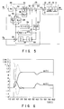
- Fig. 2 shows the response waveform in a case where a setting time Tc is one second.
- a solid line shows a case in which the reference value is input to R1
- a chain line shows the case in which the reference value is input to R2. There is no difference therebetween in the response to the disturbance.
- Fig. 3 is a structural diagram showing a controller relating to the second embodiment of the present invention. Similar to the first embodiment, this embodiment shows a case in which the reference value and the disturbance are set to be a step function (1/s), and the controlled object 10 to be controlled is shown in the integrator 11.
- a controller 22 comprises first to fourth adder-subtracters 29, 35, 31, 32, first and second integrating amplifiers 30 and 36, first and second linear amplifiers 28 and 33, and a delay element 34.
- An reference value is input to the first linear amplifier 28 whose gain is set to Ka.
- the first adder-subtracter 29 receives an output value of the first linear amplifier 28, further receives an output value of the second adder-subtracter 35, and subtracts the output of the second adder-subtracter 35 from the output value of the first linear amplifier 28.
- the first integrator 30 has a transfer function Ki/S, integrates the output value of the first adder-subtracter 29, and outputs the integrated value to the third adder-subtracter 31.
- the third adder-subtracter 31 subtracts the output value of the second linear amplifier 33 from the output value of the first integrator 30.
- the fourth adder-subtracter 32 adds an output value of the delay element 34 and the output value of the third adder-subtracter 31, and supplies the added value to the controlled object 10 as the manipulated variable.
- the second adder-subtracter 35 subtracts an output value of the second integrator 36 and a step reference value R2 supplied from an external from the control value eo output from the controlled object 10.
- the output value of the second adder-subtracter 35 is supplied to the first adder-subtracter 29, the delay element 34, and the second linear amplifier 33, respectively.
- the delay element 34 delays the output value of the second adder-subtracter 35 by Kd (1 - ⁇ -sTc ) and outputs the delayed value.
- the second integrator 36 integrates the output value of the delay element 34 by the transfer function 1/s, and outputs the integrated value to the second adder-subtracter 35.
- the second linear amplifier 33 linearly amplifies the output value of the second adder-subtracter 35 by gain of Kp, and outputs the amplified value to the third adder-subtracter 31.
- an attenuation sine wave which is an exponential function, is selected as a target response waveform f (t).
- the attenuation sine wave includes four parameters, that is, an amplitude b, an attenuation factor ⁇ , an angular frequency ⁇ 1, and a phase ⁇ 1. These parameters seem to be determined by the equations (27) to (30).
- Fig. 4 shows the response waveforms based on these numerical examples. More specifically, Fig.
- the response to the reference value R1 is shown by a solid line and the response to the reference value R2 is shown by a broken line.
- Fig. 5 shows the structure of the controller relating to the third embodiment.
- the controlled object 10 is shown by the integrator 11 and a time-lag of first order 13, and the transfer function Gp (s) of the controlled object is 1/ ⁇ (s + ⁇ c) ⁇ .
- a controller 23 of the controller of the third embodiment comprises first to sixth adder-subtracters 50, 56, 52, 53, 54, and 62, first to fifth integrators 51, 60, 63, 57, and 64, first to fourth linear amplifiers 49, 55, 58, and 59, and a delay element 61.
- an reference value is input to the first linear amplifier 49 whose gain is set to Ka.
- the first adder-subtracter 50 receives an output value of the first linear amplifier 49, further receives an output value of the second adder-subtracter 56, and subtracts the output of the second adder-subtracter 56 from the output value of the first linear amplifier 49.
- the first integrator 51 has a transfer function Ki2/S, integrates the output value of the first adder-subtracter 50 by a transfer function Ki2/S, and outputs the integrated value to the third adder-subtracter 52.
- the third adder-subtracter 52 subtracts the output value of the second linear amplifier 55 from the output value the first integrator 51.
- the subtracted value is supplied to the fourth adder-subtracter 53.
- the fourth adder-subtracter 53 subtracts the output value of the third adder-subtracter 52 from an output value of the delay element 59 and further outputs the subtracted value to the fifth adder-subtracter 54.
- the fifth adder-subtracter 54 receives an output value from the second integrator 60 and adds the output value of the fourth adder-subtracter 53 and the output value of the second integrator 60, and supplies the added value to the controlled object 10 as a manipulated variable.
- the reference value R2 and the controlled variable eo output from the controlled object 10 are supplied to the sixth adder-subtracter 62.
- the sixth adder-subtracter 62 subtracts the output value of the third integrator 63 and the reference value R2 from the controlled variable output from the controlled object 10.
- the subtracted value of the the sixth adder-subtracter 62 is supplied to the fourth integrator 57, third linear amplifier 58, fourth linear amplifier 59, and the delay element 61.
- the fourth integrator 57 integrates the output value of the sixth adder-subtracter 62 by the transfer function Ki1/S, and outputs the integrated value to the second adder-subtracter 56. Also, the third linear amplifier 58 linearly amplifies the output value of the sixth adder-subtracter 62 with gain of Kp1, and outputs the value to the second adder-subtracter 56.
- the fourth linear amplifier 59 whose gain is set to (Ki1 + Ki2) and linearly amplifies the output value of the sixth adder-subtracter 62.
- the delay element 61 delays the output value of the sixth adder-subtracter 62 by Kd (1 - ⁇ -sTc ) and outputs the the delayed value.
- the second adder-subtracter 56 adds the output value of the fourth integrator 57 and that of the third linear amplifier 58 and outputs the added value to the first adder-subtracter 50 and the second linear amplifier 55.
- the second linear amplifier 55 linear amplifies the output value of the second adder-subtracter 56 with gain of KP2 and supplies the value to the third adder-subtracter 52.
- the second integrator 60 linearly integrates the output value of the delay element 61 by the transfer function (s + ⁇ c)/s. Moreover, the fifth integrator 64 integrates the output value of the delay element 61 by the transfer function 1/S.
- the disturbance D (s) is the step function
- the relative degree of the controlled object Gp (s) is 2
- a polynomial can be relatively easily obtained as a waveform f (t) to be a target. Due to this, this embodiment shows a case of an attenuation sine wave. Since eight conditional expressions can be satisfied, the following equation (52) in which a constant value a is added to two attenuation sine waves is selected.
- f(t) a + b ⁇ - ⁇ t sin( ⁇ 1t + ⁇ 1)+ c ⁇ - ⁇ t sin( ⁇ 2t + ⁇ 2)
- F (s) in which f (t) is Laplace-transformed at time between 0 and Tc is obtained and rearranged by the function, which is obtained from the conditional expressions (47) to (51), F (s) can be expressed by the following equation (53).
- two reference value inputs R1 and R2 can be finitely set. If the setting time Tc and the time-lag of first order ⁇ c are given, a, ⁇ , ⁇ 1, ⁇ , ⁇ 2 are determined from the four equations, which can be obtained by eliminating b, c, ⁇ 1, ⁇ 2, from the relation among the equations (47) to (55), and the equation (55).
- the examples of the numerical values are shown as follows.
- the response to the reference value R1 (s) is shown by a solid line and the response to the reference value R2 (s) is shown by a broken line.
- the structure of the controller can be also obtained. This is extremely easier than the conventional case in which the structure of the control operation section must be determined by a trial and error method.
- these control operation sections can obtain the similar response. Therefore, the deadbeat control of the sample-data system, which is better than the conventional deadbeat control of the sample-data system, can be obtained.
- the deadbeat control which is realized by the controller of the present invention, can set the responses to the reference value and the disturbance at finite time.
- the deadbeat control has a feature of the continuous control, which is smooth and strong against the change of the parameters of the control system and a feature of the control, which can set the responses at finite time. Therefore, the deadbeat control having such good features can be performed and can be applied to the controlled object to be controlled in the various technical fields, and can bring about a considerable effect.
Landscapes
- Engineering & Computer Science (AREA)
- Physics & Mathematics (AREA)
- General Physics & Mathematics (AREA)
- Automation & Control Theory (AREA)
- Health & Medical Sciences (AREA)
- Artificial Intelligence (AREA)
- Computer Vision & Pattern Recognition (AREA)
- Evolutionary Computation (AREA)
- Medical Informatics (AREA)
- Software Systems (AREA)
- Feedback Control In General (AREA)
Applications Claiming Priority (2)
| Application Number | Priority Date | Filing Date | Title |
|---|---|---|---|
| JP3097371A JP2567158B2 (ja) | 1991-04-26 | 1991-04-26 | 制御装置 |
| JP97371/91 | 1991-04-26 |
Publications (3)
| Publication Number | Publication Date |
|---|---|
| EP0510649A2 true EP0510649A2 (de) | 1992-10-28 |
| EP0510649A3 EP0510649A3 (en) | 1993-01-20 |
| EP0510649B1 EP0510649B1 (de) | 1997-07-09 |
Family
ID=14190654
Family Applications (1)
| Application Number | Title | Priority Date | Filing Date |
|---|---|---|---|
| EP92106967A Expired - Lifetime EP0510649B1 (de) | 1991-04-26 | 1992-04-23 | Steuerung mit Rückkoppelung |
Country Status (8)
| Country | Link |
|---|---|
| US (1) | US5250887A (de) |
| EP (1) | EP0510649B1 (de) |
| JP (1) | JP2567158B2 (de) |
| KR (1) | KR950007103B1 (de) |
| CN (1) | CN1060273C (de) |
| AU (1) | AU638188B2 (de) |
| CA (1) | CA2066787C (de) |
| DE (1) | DE69220712T2 (de) |
Families Citing this family (10)
| Publication number | Priority date | Publication date | Assignee | Title |
|---|---|---|---|---|
| US5481453A (en) * | 1994-08-25 | 1996-01-02 | Corporation De L'ecole Polytechnique | Dual loop PID configuration |
| JP3308828B2 (ja) * | 1996-10-18 | 2002-07-29 | 株式会社日立製作所 | 永久磁石回転電機及びそれを用いた電動車両 |
| JP3802692B2 (ja) * | 1998-11-06 | 2006-07-26 | 日立ビアメカニクス株式会社 | サーボ制御装置 |
| US20040133286A1 (en) * | 2001-01-10 | 2004-07-08 | Takehiko Futatsugi | Automatic control system |
| US20060173558A1 (en) * | 2003-08-28 | 2006-08-03 | Adtex Inc. | Digital control method that control error is improved |
| JP4764785B2 (ja) * | 2006-08-23 | 2011-09-07 | ルネサスエレクトロニクス株式会社 | 同期電動機の制御装置 |
| JP4997139B2 (ja) * | 2008-02-21 | 2012-08-08 | アズビル株式会社 | モデリング装置 |
| CN107546998B (zh) * | 2017-07-25 | 2019-12-10 | 华南理工大学 | 一种基于双环预测控制的切换型控制方法 |
| JP6858725B2 (ja) * | 2018-04-20 | 2021-04-14 | 株式会社京三製作所 | Dc/dcコンバータ、及びdc/dcコンバータの制御方法 |
| CN111181460B (zh) * | 2020-01-09 | 2022-09-06 | 湖南大学 | 单定子双转子盘式对转永磁同步电机的动态电流预测控制方法、系统及介质 |
Family Cites Families (9)
| Publication number | Priority date | Publication date | Assignee | Title |
|---|---|---|---|---|
| US4432439A (en) * | 1982-03-10 | 1984-02-21 | Westinghouse Electric Corp. | Elevator system |
| US4675804A (en) * | 1983-11-01 | 1987-06-23 | Sundstrand Corporation | Control system with variable gain integrator |
| JPS60254201A (ja) * | 1984-05-30 | 1985-12-14 | Toshiba Corp | 制御装置 |
| DD269240A1 (de) * | 1987-06-10 | 1989-06-21 | Univ Dresden Tech | Verfahren und schaltungsanordnung zur adaptiven regelung der drehzahl elektrischer antriebe |
| JPH0673081B2 (ja) * | 1987-11-25 | 1994-09-14 | 株式会社日立製作所 | 自動制御装置 |
| US4894599A (en) * | 1988-03-31 | 1990-01-16 | International Business Machines Corporation | deadbeat control of disk drive actuator |
| US4982145A (en) * | 1989-09-08 | 1991-01-01 | Aeg Westinghouse Industrial Automation Corporation | Method and apparatus for the optimization of thyristor power supply transport time delay |
| AU611839B1 (en) * | 1989-09-11 | 1991-06-20 | Kabushiki Kaisha Toshiba | Two degree of freedom controller |
| JPH03100801A (ja) * | 1989-09-14 | 1991-04-25 | Toshiba Corp | 制御装置 |
-
1991
- 1991-04-26 JP JP3097371A patent/JP2567158B2/ja not_active Expired - Fee Related
-
1992
- 1992-04-22 CA CA002066787A patent/CA2066787C/en not_active Expired - Fee Related
- 1992-04-23 DE DE69220712T patent/DE69220712T2/de not_active Expired - Fee Related
- 1992-04-23 EP EP92106967A patent/EP0510649B1/de not_active Expired - Lifetime
- 1992-04-24 US US07/873,191 patent/US5250887A/en not_active Expired - Fee Related
- 1992-04-24 AU AU15183/92A patent/AU638188B2/en not_active Ceased
- 1992-04-25 CN CN92103988A patent/CN1060273C/zh not_active Expired - Fee Related
- 1992-04-27 KR KR92007112A patent/KR950007103B1/ko not_active Expired - Fee Related
Also Published As
| Publication number | Publication date |
|---|---|
| EP0510649A3 (en) | 1993-01-20 |
| KR920020295A (ko) | 1992-11-20 |
| CA2066787C (en) | 1996-03-19 |
| CN1060273C (zh) | 2001-01-03 |
| JP2567158B2 (ja) | 1996-12-25 |
| DE69220712T2 (de) | 1997-12-18 |
| US5250887A (en) | 1993-10-05 |
| AU1518392A (en) | 1992-11-19 |
| DE69220712D1 (de) | 1997-08-14 |
| KR950007103B1 (en) | 1995-06-30 |
| EP0510649B1 (de) | 1997-07-09 |
| JPH04326401A (ja) | 1992-11-16 |
| CA2066787A1 (en) | 1992-10-27 |
| AU638188B2 (en) | 1993-06-17 |
| CN1067750A (zh) | 1993-01-06 |
Similar Documents
| Publication | Publication Date | Title |
|---|---|---|
| EP0510649A2 (de) | Steuerung mit Rückkoppelung | |
| EP0296638B1 (de) | Prozesssteuerung mit einer Kombination von direkter und rückgekoppelter Steuerung | |
| KR100242447B1 (ko) | 로봇 제어를 위한 경로 계획 장치 및 경로 계획 방법 | |
| JPH0635505A (ja) | 自動制御装置 | |
| EP0453259B1 (de) | Regler mit zwei Freiheitsgraden | |
| EP0518651A2 (de) | Prozesssteuerung | |
| SE446664B (sv) | Anordning och sett for att undanroja lasning i ett fjederupphengt ringlasergyro | |
| US5483439A (en) | Digital servo control system | |
| JPH03100801A (ja) | 制御装置 | |
| EP0445940B1 (de) | Prozessregelungsvorrichtung | |
| EP0483364B1 (de) | Diskretes wiederholungssteuerverfahren und vorrichtung dafür | |
| US5200681A (en) | Process control system | |
| Lu et al. | Discrete-time model reference adaptive control for nonminimum phase systems with disturbances using approximate inverse systems | |
| RU2114455C1 (ru) | Способ автоматического управления в системе с люфтом и следящая система для его осуществления | |
| RU2171489C1 (ru) | Двухканальная система автоматического управления нестационарным объектом | |
| JPH0797285B2 (ja) | プロセス制御装置 | |
| Domek | for Fractional-Order Systems | |
| JPH04256102A (ja) | モデル予測制御装置 | |
| RU2230350C2 (ru) | Самонастраивающаяся система автоматического управления нестационарным объектом | |
| Hurák et al. | Minimization of 𝓁2 norm of the error signal in posicast input command shaping: a polynomial approach | |
| Amaral et al. | Robustness filter design for the Simplified Filtered Smith Predictor with disturbance rejection | |
| Myrhorod et al. | MATHEMATICAL DESCRIPTION AND OPTIMIZATION BY THE QUADRATIC QUALITY CRITERION OF AUTOMATIC CONTROL SYSTEMS USING PULSE WIDTH MODULATION OF SIGNALS | |
| Hammad et al. | Taming chaos: A numerical experiment using low-order LTI filters | |
| RU50323U1 (ru) | Комбинированная система координатно-параметрического управления нестационарным нелинейным объектом | |
| Chang | Dynamics of a sliding control with a first-order plus integral sliding condition |
Legal Events
| Date | Code | Title | Description |
|---|---|---|---|
| PUAI | Public reference made under article 153(3) epc to a published international application that has entered the european phase |
Free format text: ORIGINAL CODE: 0009012 |
|
| 17P | Request for examination filed |
Effective date: 19920520 |
|
| AK | Designated contracting states |
Kind code of ref document: A2 Designated state(s): CH DE FR GB LI SE |
|
| PUAL | Search report despatched |
Free format text: ORIGINAL CODE: 0009013 |
|
| AK | Designated contracting states |
Kind code of ref document: A3 Designated state(s): CH DE FR GB LI SE |
|
| RHK1 | Main classification (correction) |
Ipc: G05B 11/42 |
|
| 17Q | First examination report despatched |
Effective date: 19941207 |
|
| GRAG | Despatch of communication of intention to grant |
Free format text: ORIGINAL CODE: EPIDOS AGRA |
|
| GRAH | Despatch of communication of intention to grant a patent |
Free format text: ORIGINAL CODE: EPIDOS IGRA |
|
| GRAH | Despatch of communication of intention to grant a patent |
Free format text: ORIGINAL CODE: EPIDOS IGRA |
|
| GRAA | (expected) grant |
Free format text: ORIGINAL CODE: 0009210 |
|
| AK | Designated contracting states |
Kind code of ref document: B1 Designated state(s): CH DE FR GB LI SE |
|
| REG | Reference to a national code |
Ref country code: CH Ref legal event code: NV Representative=s name: E. BLUM & CO. PATENTANWAELTE Ref country code: CH Ref legal event code: EP |
|
| REF | Corresponds to: |
Ref document number: 69220712 Country of ref document: DE Date of ref document: 19970814 |
|
| ET | Fr: translation filed | ||
| PLBE | No opposition filed within time limit |
Free format text: ORIGINAL CODE: 0009261 |
|
| STAA | Information on the status of an ep patent application or granted ep patent |
Free format text: STATUS: NO OPPOSITION FILED WITHIN TIME LIMIT |
|
| 26N | No opposition filed | ||
| REG | Reference to a national code |
Ref country code: GB Ref legal event code: 746 Effective date: 19981010 |
|
| REG | Reference to a national code |
Ref country code: FR Ref legal event code: D6 |
|
| PGFP | Annual fee paid to national office [announced via postgrant information from national office to epo] |
Ref country code: SE Payment date: 19990406 Year of fee payment: 8 |
|
| PGFP | Annual fee paid to national office [announced via postgrant information from national office to epo] |
Ref country code: FR Payment date: 19990409 Year of fee payment: 8 |
|
| PGFP | Annual fee paid to national office [announced via postgrant information from national office to epo] |
Ref country code: GB Payment date: 19990421 Year of fee payment: 8 |
|
| PGFP | Annual fee paid to national office [announced via postgrant information from national office to epo] |
Ref country code: CH Payment date: 19990428 Year of fee payment: 8 |
|
| PGFP | Annual fee paid to national office [announced via postgrant information from national office to epo] |
Ref country code: DE Payment date: 19990430 Year of fee payment: 8 |
|
| PG25 | Lapsed in a contracting state [announced via postgrant information from national office to epo] |
Ref country code: GB Free format text: LAPSE BECAUSE OF NON-PAYMENT OF DUE FEES Effective date: 20000423 |
|
| PG25 | Lapsed in a contracting state [announced via postgrant information from national office to epo] |
Ref country code: SE Free format text: LAPSE BECAUSE OF NON-PAYMENT OF DUE FEES Effective date: 20000424 |
|
| PG25 | Lapsed in a contracting state [announced via postgrant information from national office to epo] |
Ref country code: LI Free format text: LAPSE BECAUSE OF NON-PAYMENT OF DUE FEES Effective date: 20000430 Ref country code: CH Free format text: LAPSE BECAUSE OF NON-PAYMENT OF DUE FEES Effective date: 20000430 |
|
| EUG | Se: european patent has lapsed |
Ref document number: 92106967.0 |
|
| GBPC | Gb: european patent ceased through non-payment of renewal fee |
Effective date: 20000423 |
|
| REG | Reference to a national code |
Ref country code: CH Ref legal event code: PL |
|
| PG25 | Lapsed in a contracting state [announced via postgrant information from national office to epo] |
Ref country code: FR Free format text: LAPSE BECAUSE OF NON-PAYMENT OF DUE FEES Effective date: 20001229 |
|
| PG25 | Lapsed in a contracting state [announced via postgrant information from national office to epo] |
Ref country code: DE Free format text: LAPSE BECAUSE OF NON-PAYMENT OF DUE FEES Effective date: 20010201 |
|
| REG | Reference to a national code |
Ref country code: FR Ref legal event code: ST |