EP0510841B1 - Interaktives Objekt eines Spielfelds für Flipperspiel - Google Patents
Interaktives Objekt eines Spielfelds für Flipperspiel Download PDFInfo
- Publication number
- EP0510841B1 EP0510841B1 EP92303211A EP92303211A EP0510841B1 EP 0510841 B1 EP0510841 B1 EP 0510841B1 EP 92303211 A EP92303211 A EP 92303211A EP 92303211 A EP92303211 A EP 92303211A EP 0510841 B1 EP0510841 B1 EP 0510841B1
- Authority
- EP
- European Patent Office
- Prior art keywords
- pinball
- playfield
- game according
- microprocessor
- pinball game
- Prior art date
- Legal status (The legal status is an assumption and is not a legal conclusion. Google has not performed a legal analysis and makes no representation as to the accuracy of the status listed.)
- Expired - Lifetime
Links
Images



Classifications
-
- A—HUMAN NECESSITIES
- A63—SPORTS; GAMES; AMUSEMENTS
- A63F—CARD, BOARD, OR ROULETTE GAMES; INDOOR GAMES USING SMALL MOVING PLAYING BODIES; VIDEO GAMES; GAMES NOT OTHERWISE PROVIDED FOR
- A63F7/00—Indoor games using small moving playing bodies, e.g. balls, discs or blocks
- A63F7/22—Accessories; Details
- A63F7/30—Details of the playing surface, e.g. obstacles; Goal posts; Targets; Scoring or pocketing devices; Playing-body-actuated sensors, e.g. switches; Tilt indicators; Means for detecting misuse or errors
- A63F7/305—Goal posts; Winning posts for rolling-balls
- A63F7/3065—Electric
-
- A—HUMAN NECESSITIES
- A63—SPORTS; GAMES; AMUSEMENTS
- A63F—CARD, BOARD, OR ROULETTE GAMES; INDOOR GAMES USING SMALL MOVING PLAYING BODIES; VIDEO GAMES; GAMES NOT OTHERWISE PROVIDED FOR
- A63F9/00—Games not otherwise provided for
- A63F9/24—Games using electronic circuits not otherwise provided for
- A63F2009/2448—Output devices
- A63F2009/247—Output devices audible, e.g. using a loudspeaker
- A63F2009/2476—Speech or voice synthesisers, e.g. using a speech chip
Definitions
- the present invention relates generally to playfield features for pinball games, and more particularly to a multi-function interactive playfield feature for such games.
- Pinball games as commonly known (e.g. US-A-4.763.256), consist of an inclined playfield and a plurality of features arranged on the playfield. A player uses flippers or similar means to direct a pinball at the playfield features such as targets or ramps in order to score points. Even though a variety of pinball game features are currently in use, constant addition of novel and exciting features is desirable to attract the greatest possible number of players to a particular pinball game.
- Conventional pinball games have playfield features that respond to contact by the pinball. These playfield features lack the capability to communicate with the game player and direct attention toward specific activities on the playfield. A playfield feature having the capability to interact with the game player is desirable.
- the present invention is a computer-controlled interactive playfield feature for pinball games.
- the system microprocessor monitors activity on the playfield and controls the interactive playfield feature, directing the player's attention to specific targets and activities on the playfield.
- the interactive playfield feature is in the shape of a speciesar human head.
- the mouth is operated by an electric motor under microprocessor control. In either the open or closed position, the mouth serves as a ball target toward which the player is encouraged to direct his skill shots. When closed, the lower lip prevents the ball from entering the mouth. When the player gets the ball in the open mouth, points are awarded and bonus features may be activated.
- a solenoid ball ejector returns the ball to the playfield.
- the mouth may be operated in conjunction with a speech synthesizer associated with the game's controlling microprocessor to give the appearance of speech. This function may be used to taunt and challenge game players, increasing player appeal.
- the eyelids are movable, and are operated by solenoids in conjunction with mechanical linkages under microprocessor control to give the head a more lifelike appearance.
- the eyes are operated by a pair of pull-pull solenoids.
- eye movement may be controlled so as to follow the path of the pinball as it travels on the playfield, responsive to playfield sensors, which indicate the ball position to the system microprocessor.
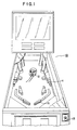
- FIG. 1 is a perspective view of a pinball game having the interactive playfield feature of the present invention installed thereon.
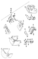
- FIG. 2 is an exploded view of the interactive playfield feature of the present invention.
- FIG. 3 is a front view of the interactive playfield feature of the present invention with the covers removed.
- FIG. 4 is a side view of the interactive playfield feature of the present invention with the covers removed.
- FIG. 5 is a top view of the interactive playfield feature of the present invention.
- FIG. 6A, FIG. 6B and FIG. 6C are side views in partial section showing the operation of the solenoid-controlled plastic eyelids of the present invention.
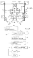
- FIG. 7 is a block diagram useful in explaining the control of the interactive playfield feature of the present invention via the system microprocessor.
- FIG. 1 shows a pinball game 10 having an interactive playfield feature 12 mounted on an inclined playfield 14.
- a spring-loaded plunger 13 is provided to allow the player to propel the ball onto the playfield 14.
- the playfield is equipped with a plurality of conventional playfield features, such as bumpers, ramps, and other targets, all of which have ball-activated sensors associated therewith. While mechanical switches and optical switches are commonly used for this purpose, it is within the contemplation of the invention that any means for signalling the presence of the ball may be substituted therefor.
- the game player may direct skill shots at these targets by controlling a set of flippers 15.
- FIG. 2 shows an exploded view of the interactive playfield feature of the present invention.
- FIG. 3, FIG. 4 and FIG. 5 are also useful in explaining the construction of the present invention.
- the mechanical and electrical components comprising the interactive playfield feature are supported by a metal frame 16, which is secured to the playfield 14.
- a wooden panel 18 is secured within the frame 16, forming its bottom.
- the panel 18 has a centrally disposed aperture 20 for receiving the pinball during game play.
- a ball trap assembly 22 is secured to the panel 18, extending upwardly through the aperture 20.
- the ball trap 22 receives a pinball, forcing it into the aperture 20.
- a ball ejector solenoid 24 Secured to the ball trap 22 is a ball ejector solenoid 24, which returns the pinball to the playfield 14 after it is caught in the ball trap 22.
- a switch assembly 25 is secured to the bottom of the panel 18. The switch assembly 25 signals the system microprocessor when a pinball enters the ball trap 22.
- a plastic mouth member 26 (see FIG. 4) is secured to the frame 16 for reciprocating pivotal motion between an upper position and a lower position, as well as any intermediate position.
- the mouth member 26 is driven by a motor and gear arrangement under microprocessor control, as is commonly known in the art.
- the mouth member 26 includes side members 26a and 26b, which form the sides of the ball trap.
- the mouth member 26 is biased forwardly by a pair of springs 28 connected between the ball trap 22 and the hinged ends of the side members 26a and 26b.
- the springs 28 provide a cushion so that shock is absorbed by the spring when the mouth member 26 is struck by the pinball during the course of play.
- a pair of simulated eyes 30 are mounted for left and right pivoting motion on a bracket 32, which is secured within the frame 16.
- the eyes are connected to a lever arm 34 via a pair of linkage members 36 (see FIG. 5).
- the lever arm 34 is secured for pivotal motion to a point on the inside top of the frame 16.
- a centering rod 38 is secured between the sides of the frame 16. The centering rod 38 abuts the end of the lever arm 34, so that it is displaced rearwardly whenever the eyes 30 are rotated in either direction.
- the centering rod 38 centers the lever arm 34, so that the eyes 30 point straight ahead.
- a pair of solenoids 40 having a common plunger shaft 42 is secured in pull-pull configuration within the frame 16.
- a camming member 44 is disposed on the plunger 42 for cooperation with a slot 46 in the upper surface of the lever arm 34.
- the shaft 42 is reciprocated under microprocessor control. When power is supplied to one of the solenoids, the other solenoid remains unpowered. Thus, the shaft 42 is pulled toward the solenoid to which power is supplied. Power may be applied to the other solenoid 40 to cause the plunger shaft to travel in the opposite direction.
- the camming member 44 engages the edges of the slot 46, rotating the lever arm 34, causing the eyes 30 to travel in the opposite direction of plunger shaft movement.
- a pair of simulated eyelids 48 is mounted for reciprocal motion within the frame 16.
- the eyelids 48 are controlled by a pair of solenoids 50, 52, and may be positioned in either an open, closed or overdriven position under control of the system microprocessor.
- the vertically positioned solenoid 50 is secured to the side of the frame 16 and is connected to the eyelids by a rigid locking member 54.
- the solenoid 52 is horizontally positioned on the side of the frame 16 so that the plunger reciprocates in a direction perpendicular to the plunger of the solenoid 50.
- a latching arm 56 is attached to the plunger of the solenoid 52.
- the locking member 54 passes through a slot 58 in the latching arm 56.
- a tab 60 extends from the locking member 54.
- the tab 60 cooperates with the latching arm 56 to restrict the travel of the plunger of the solenoid 50.
- Springs 62 and 64 are concentrically disposed about the plungers of the solenoids 50 and 52 to bias them to a fully extended position in their de-energized state.
- a molded plastic face 53 is secured to the front of the frame 16.
- the face 53 has apertures to accommodate the eyes 30, eyelids 48 and mouth 26.
- a molded plastic head 55 is secured to the back of the frame 16.
- FIG. 6A, 6B and 6C are useful for explaining the operation of the eyelids 48.
- FIG. 6A shows the eyelids in a wide open position.
- the solenoid 50 is overdriven by the system microprocessor, fully retracting its plunger.
- the eyelids 48 are reciprocated toward a fully open position. This overdriven position is useful in manifesting a surprised expression on the face of the interactive playfield feature of the present invention.
- FIG. 6B shows the eyelids in an open position.
- the solenoid 52 must be unpowered to allow the spring 64 to bias the latching arm 56 to a fully extended position.
- the latching arm 56 is made to abut the edge of the locking member 54.
- the solenoid 50 is de-energized, the spring 62 will bias its plunger toward fully extended position, causing the tab 60 to engage the latching arm 56.
- the engagement of the tab 60 with the latching arm 58 prevents further travel of the plunger of the solenoid 50, causing the eyelids to remain in the open position until the tab 60 is disengaged from the latching arm 56 by energizing the solenoid 52.
- FIG. 6C shows the eyelids 48 in closed position.
- the solenoid 52 is energized while the solenoid 50 is de-energized.
- the tab 60 clears the latching arm 56 as the spring 62 returns the plunger of the solenoid 50 to fully extended position.
- the eyelids 48 are reciprocated to fully closed position.
- FIG. 7 is a block diagram useful in explaining the operation of the interactive playfield feature of the present invention.
- a system microprocessor 66 controls the interactive playfield feature 12 via a bus 68. This configuration is well-known in the art.
- the bus 68 also connects the microprocessor 66 to a plurality of pinball-actuated sensors 72, a speech synthesizer 74, a read-only memory (“ROM”) 76 and a random access memory (“RAM”) 78.
- the ROM 76 contains executable software which is used by the microprocessor 66 to control the operation of the pinball game, including the interactive playfield feature of the present invention.
- the sensors 72 signal the microprocessor 66 when contacted by the pinball.
- switches to update game scoring or activate playfield features is well-known in the art.
- U.S. Patent No. 4,763,256 to Demar the DeMar patent
- the DeMar patent teaches the monitoring of switches on the playfield to detect inoperative features. Additionally, switch closure information has been used to signal the system microprocessor to activate different playfield features when an active target is hit by the pinball.
- the microprocessor 66 employs the switch closure information to determine the location of the pinball on the playfield. This may be accomplished, for example, by relating each switch to a specific co-ordinate location on playfield via a look-up table in the system ROM 76.
- the ROM 76 may store the co-ordinate locations of typical ball paths to allow the microprocessor 66 to anticipate the ball position and correct this estimate based on actual switch closure data.
- the microprocessor 66 may be programmed to operate the interactive playfield feature 12 to give the appearance that the eyes 30 are following the travel of the pinball. This novel effect creates great player interest in the game.
- the eyelids 48 may be controlled to enhance the expression on the face 53, showing fear when the ball is in close proximity or mockery when the player misdirects a skill shot.
- the microprocessor 66 may also operate the speech synthesizer 74 in conjunction with the mouth of the interactive playfield feature 14 to give the appearance that the playfield feature 14 is speaking to the player. These messages may taunt the player and encourage him to attempt to shoot the pinball into the mouth of the interactive playfield feature 14 or at various other activated targets. Because the microprocessor knows the location of the pinball from the sensor information, the comments of the interactive playfield feature can be tailored to reflect the current game status. The microprocessor 66 awards points for each successful skill shot.
Landscapes
- Engineering & Computer Science (AREA)
- Multimedia (AREA)
- Pinball Game Machines (AREA)
Claims (17)
- Flipperspiel, welches folgendes umfaßt: Ein geneigtes Spielfeld (14) zum Tragen eines rollenden Flipper-Balls, eine vom Spieler bediente Einrichtung (15) zum Schleudern des Flipper-Balls auf im Spielfeld (14) angeordnete Ziele, mehrere den Zielen zugeordnete, vom Flipper-Ball aktivierte Sensoren (72), wobei jeder Sensor (72) beim Aktivieren durch den Flipper-Ball ein Signal erzeugt, und einen Mikroprozessor (66) zum Empfang der von den Sensoren (72) kommenden Signale, dadurch gekennzeichnet, daß der Mikroprozessor (66) eine Einrichtung zur Bestimmung der Stelle, an der sich der Flipper-Ball auf dem Spielfeld (14) befindet, und zwar auf der Basis der empfangenen Signale umfaßt, und daß ein interaktives Spielfeldmerkmal (12) vorgesehen ist, welches Einrichtungen (26, 30, 48) zum Ansprechen auf Ausgaben des Mikroprozessors (66) derart umfaßt, daß das interaktive Spielfeldmerkmal (12) abhängig von der Stelle, an der sich der Flipper-Ball auf dem Spielfeld (14) befindet, auf die Bewegung des Flipper-Balls anspricht.
- Flipperspiel nach Anspruch 1, bei dem das interaktive Spielfeldmerkmal (12) einen simulierten menschlichen Kopf (53, 55) umfaßt.
- Flipperspiel nach Anspruch 1 oder Anspruch 2, welches ferner einen Systemspeicher (76) umfaßt, zu dem der Mikroprozessor (66) Zugriff hat, wobei die Einrichtung zur Bestimmung der Stelle, an der sich der Flipper-Ball befindet, eine im Systemspeicher (76) gespeicherte Nachschlagetabelle umfaßt.
- Flipperspiel nach einem der vorhergehenden Ansprüche, bei dem die Ansprech-Einrichtungen einen menschliche Augen (30) simulierenden beweglichen mechanischen Aufbau umfassen.
- Flipperspiel nach einem der vorhergehenden Ansprüche, bei dem die Ansprech-Einrichtungen einen eine menschliche Kinnlade (26) simulierenden beweglichen mechanischen Aufbau umfassen.
- Flipperspiel nach Anspruch 5, bei dem die Ansprech-Einrichtungen ferner einen vom Mikroprozessor (66) gesteuerten Sprachgenerator (74) umfassen, wobei die Bewegung der Kinnlade (26) mit dem Sprachgenerator (74) synchronisiert wird, um den Eindruck zu erzeugen, daß die Sprache von der Kinnlade (26) kommt.
- Flipperspiel nach Anspruch 5 oder 6, welches eine Einrichtung zur Bewegung der Kinnlade (26) zwischen einer ersten Stellung und einer zweiten Stellung umfaßt, bei der sich ein Ziel (22) zeigt, auf das der Spieler den Flipper-Ball richten kann.
- Flipperspiel nach einem der vorhergehenden Ansprüche, welches eine Einrichtung (74) zur hörbaren Kommunikation mit dem Spieler, ansprechend auf die Bewegung des Flipper-Balls auf dem Spielfeld, umfaßt.
- Flipperspiel nach Anspruch 8, bei dem die Einrichtung zur hörbaren Kommunikation einen vom Mikroprozessor gesteuerten Sprachgenerator (74) umfaßt.
- Flipperspiel, welches folgendes umfaßt: Ein geneigtes Spielfeld (14) zum Tragen eines rollenden Flipper-Balls, eine vom Spieler bediente Einrichtung (15) zum Schleudern des Flipper-Balls auf im Spielfeld (14) angeordnete Ziele, mehrere auf dem Spielfeld (14) angeordnete Sensoren (72) zum Erzeugen eines Signals nach Aktivierung durch den Flipper-Ball, gekennzeichnet durch eine Einrichtung (66) zum Empfang der von den Sensoren kommenden Signale und zur Bestimmung der Stelle, an der sich der Flipper-Ball auf dem Spielfeld (14) befindet, und zwar auf der Basis der empfangenen Signale, eine von einer Steuereinrichtung (66) gesteuerte Einrichtung (74) zur hörbaren Kommunikation mit dem Spieler, ansprechend auf die vom Flipper-Ball aktivierten Sensoren abhängig von der Stelle, an der sich der Flipper-Ball auf dem Spielfeld (14) befindet, und ein von der Steuereinrichtung (66) gesteuertes interaktives Spielfeldmerkmal (12), welches Einrichtungen, unter anderem einen simulierten Kopf (53, 55) mit einer beweglichen Kinnlade (26), zum Ansprechen auf die Steuereinrichtung (66) derart umfaßt, daß das interaktive Spielfeldmerkmal (12) auf die Bewegung des Flipper-Balls anspricht.
- Flipperspiel nach Anspruch 10, bei dem die Einrichtung zur hörbaren Kommunikation einen Sprachgenerator (74) umfaßt.
- Flipperspiel nach Anspruch 11, bei dem die Steuereinrichtung die Kinnlade (26) bewegt und den Sprachgenerator (74) steuert, um den Anschein zu erwecken, daß der Kopf (53, 55) spricht.
- Flipperspiel nach einem der Ansprüche 10 bis 12, bei dem die Ansprech-Einrichtungen einen ersten beweglichen mechanischen Aufbau umfassen, der so gestaltet ist, daß er Augen (30) simuliert.
- Flipperspiel nach Anspruch 13, bei dem die Ansprech-Einrichtungen ferner einen zweiten beweglichen mechanischen Aufbau umfassen, der so gestaltet ist, daß er Augenlider (48) simuliert.
- Flipperspiel nach Anspruch 14, bei dem die Ansprech-Einrichtungen den ersten und den zweiten beweglichen mechanischen Aufbau bewegen, und zwar ansprechend auf die Stelle, an der sich der Flipper-Ball auf dem Spielfeld (14) befindet, um den Anschein zu erwecken, daß die simulierten Augen (30) der Bewegung des Flipper-Balls folgen.
- Flipperspiel nach einem der Ansprüche 10 bis 15, welches ferner eine Zieleinrichtung (22) umfaßt, wobei die bewegliche Kinnlade (26) vor der Zieleinrichtung (22) angeordnet ist und zwischen einer ersten Stellung, bei der die Zieleinrichtung (22) für den Flipper-Ball freiliegt, und einer zweiten Stellung, bei der die Zieleinrichtung (22) dem Flipper-Ball verborgen ist, beweglich ist.
- Flipperspiel nach Anspruch 16, bei dem die zieleinrichtung eine Ballfangeinrichtung (22) und eine Auswurfeinrichtung (24) umfaßt.
Applications Claiming Priority (2)
| Application Number | Priority Date | Filing Date | Title |
|---|---|---|---|
| US07/691,707 US5123647A (en) | 1991-04-26 | 1991-04-26 | Interactive playfield feature for pinball games |
| US691707 | 1991-04-26 |
Publications (2)
| Publication Number | Publication Date |
|---|---|
| EP0510841A1 EP0510841A1 (de) | 1992-10-28 |
| EP0510841B1 true EP0510841B1 (de) | 1995-03-22 |
Family
ID=24777624
Family Applications (1)
| Application Number | Title | Priority Date | Filing Date |
|---|---|---|---|
| EP92303211A Expired - Lifetime EP0510841B1 (de) | 1991-04-26 | 1992-04-10 | Interaktives Objekt eines Spielfelds für Flipperspiel |
Country Status (3)
| Country | Link |
|---|---|
| US (1) | US5123647A (de) |
| EP (1) | EP0510841B1 (de) |
| DE (1) | DE69201746T2 (de) |
Families Citing this family (96)
| Publication number | Priority date | Publication date | Assignee | Title |
|---|---|---|---|---|
| US5277426A (en) * | 1991-11-22 | 1994-01-11 | Donald A. Wilson | Sports simulation system |
| FR2688703B3 (fr) * | 1992-03-23 | 1994-07-01 | Williams Electronics Games Inc | Dispositif de jeu pour un billard electrique. |
| USD356602S (en) | 1992-12-22 | 1995-03-21 | Toy Biz, Inc. | Pinball machine |
| USD357282S (en) | 1992-12-22 | 1995-04-11 | Toy Biz, Inc. | Pinball machine with attached human figure |
| US5405142A (en) * | 1992-12-22 | 1995-04-11 | Toy Biz, Inc. | Pinball machine with an interactive three-dimensional figure |
| US5358244A (en) * | 1993-08-10 | 1994-10-25 | Data East Pinball, Inc. | Pinball machine with movable ball retrieval target assembly |
| US5364099A (en) * | 1994-01-18 | 1994-11-15 | Data East Pinball, Inc. | Pinball machine with novel target assembly |
| US5558373A (en) * | 1994-11-14 | 1996-09-24 | Sega Pinball, Inc. | Pinball machine with moving feature |
| US5544880A (en) * | 1995-01-13 | 1996-08-13 | Sega Pinball, Inc. | Pinball machine with ball throwing figure |
| US5507488A (en) * | 1995-03-20 | 1996-04-16 | Williams Electronics Games, Inc. | Ball diverter for a pinball game |
| US5496030A (en) * | 1995-05-02 | 1996-03-05 | Capcom Coin-Op, Inc. | Pinball kick back play feature |
| US5899454A (en) * | 1997-10-23 | 1999-05-04 | Williams Electronics Games, Inc. | Ramp with integral ball deflector for pinball games |
| US5913516A (en) * | 1998-02-02 | 1999-06-22 | Piotrowski; Peter J | Multimode target with variable trajectory ball ramp |
| US5924690A (en) * | 1998-03-16 | 1999-07-20 | Williams Electronic Games Inc. | Drop target for a pinball game |
| US5944309A (en) * | 1998-06-24 | 1999-08-31 | Williams Electronics Games, Inc. | Illuminable ramp assembly for a pinball game |
| US6149153A (en) * | 1999-05-28 | 2000-11-21 | Williams Electronics Games, Inc. | Automatic propelling feature for pinball games |
| US20050206084A1 (en) * | 2004-03-08 | 2005-09-22 | Innovative Concepts In Entertainment, Inc. | Roll-down game with moving target and interactive assembly and method for playing a roll-down game |
| US20090085287A1 (en) * | 2007-09-27 | 2009-04-02 | Daniel Bress | Dynamically Altering Pinball Playfield Elements |
| USD678958S1 (en) | 2011-09-26 | 2013-03-26 | Wms Gaming Inc. | Gaming machine |
| USD678955S1 (en) | 2011-09-26 | 2013-03-26 | Wms Gaming Inc. | Gaming machine |
| USD691666S1 (en) | 2011-09-26 | 2013-10-15 | Wms Gaming Inc. | Gaming machine |
| USD678957S1 (en) | 2011-09-26 | 2013-03-26 | Wms Gaming Inc. | Gaming machine |
| USD681130S1 (en) | 2011-09-26 | 2013-04-30 | Wms Gaming Inc. | Gaming machine |
| USD682948S1 (en) | 2011-09-26 | 2013-05-21 | Wms Gaming Inc. | Gaming machine |
| USD678956S1 (en) | 2011-09-26 | 2013-03-26 | Wms Gaming Inc. | Gaming machine |
| USD771193S1 (en) | 2011-11-11 | 2016-11-08 | Bally Gaming, Inc. | Game display screen with multiple arrays of reels |
| USD691665S1 (en) | 2012-09-26 | 2013-10-15 | Wms Gaming Inc. | Gaming machine |
| USD704273S1 (en) | 2012-09-26 | 2014-05-06 | Wms Gaming Inc. | Gaming machine |
| USD843476S1 (en) | 2013-04-17 | 2019-03-19 | Bally Gaming, Inc. | Gaming machine |
| USD712975S1 (en) | 2013-04-17 | 2014-09-09 | Wms Gaming Inc. | Gaming machine |
| USD730993S1 (en) | 2013-09-20 | 2015-06-02 | Wms Gaming Inc. | Inclined input interface for a gaming terminal |
| USD843480S1 (en) | 2018-06-01 | 2019-03-19 | Bally Gaming, Inc. | Gaming machine with curved display |
| USD843459S1 (en) | 2016-03-30 | 2019-03-19 | Bally Gaming, Inc. | Gaming machine with curved display |
| USD819747S1 (en) | 2016-03-30 | 2018-06-05 | Bally Gaming, Inc. | Gaming machine with curved display |
| USD843458S1 (en) | 2016-03-30 | 2019-03-19 | Bally Gaming, Inc. | Gaming machine with curved display |
| USD896313S1 (en) | 2016-03-30 | 2020-09-15 | Sg Gaming, Inc. | Gaming machine with curved display |
| USD832358S1 (en) | 2016-09-13 | 2018-10-30 | Bally Gaming, Inc. | Gaming machine with curved display |
| USD843461S1 (en) | 2016-09-13 | 2019-03-19 | Bally Gaming, Inc. | Gaming machine with curved display |
| USD843463S1 (en) | 2016-09-13 | 2019-03-19 | Bally Gaming, Inc. | Gaming machine with curved display |
| USD832357S1 (en) | 2016-09-13 | 2018-10-30 | Bally Gaming, Inc. | Gaming machine with curved display |
| USD843462S1 (en) | 2016-09-13 | 2019-03-19 | Bally Gaming, Inc. | Gaming machine with curved display |
| USD843465S1 (en) | 2016-09-13 | 2019-03-19 | Bally Gaming, Inc. | Gaming machine with curved display |
| USD843460S1 (en) | 2016-09-13 | 2019-03-19 | Bally Gaming, Inc. | Gaming machine with curved display |
| USD871506S1 (en) | 2016-09-13 | 2019-12-31 | Bally Gaming, Inc. | Gaming machine with curved displays |
| USD843466S1 (en) | 2016-09-13 | 2019-03-19 | Bally Gaming, Inc. | Gaming machine with curved display |
| USD832356S1 (en) | 2016-09-13 | 2018-10-30 | Bally Gaming, Inc. | Gaming machine with curved display |
| USD843464S1 (en) | 2016-09-13 | 2019-03-19 | Bally Gaming, Inc. | Gaming machine with curved display |
| USD836164S1 (en) | 2016-09-13 | 2018-12-18 | Bally Gaming, Inc. | Curved display for a gaming machine |
| USD832355S1 (en) | 2016-09-13 | 2018-10-30 | Bally Gaming, Inc. | Gaming machine with curved display |
| USD882700S1 (en) | 2017-04-14 | 2020-04-28 | Sg Gaming, Inc. | Gaming machine carousel display |
| USD882699S1 (en) | 2017-04-14 | 2020-04-28 | Sg Gaming, Inc. | Gaming machine carousel display |
| USD883393S1 (en) | 2017-04-14 | 2020-05-05 | Sg Gaming, Inc. | Gaming machine carousel display |
| USD850537S1 (en) | 2017-09-05 | 2019-06-04 | Aristocrat Technologies Australia Pty Limited | Gaming machine |
| USD889552S1 (en) | 2017-09-28 | 2020-07-07 | Sg Gaming, Inc. | Gaming terminal |
| USD915523S1 (en) | 2017-09-28 | 2021-04-06 | Sg Gaming, Inc. | Gaming terminal |
| USD880606S1 (en) | 2017-09-28 | 2020-04-07 | Sg Gaming, Inc. | Gaming terminal |
| USD889553S1 (en) | 2017-09-28 | 2020-07-07 | Sg Gaming, Inc. | Gaming terminal |
| US10328335B1 (en) * | 2018-02-27 | 2019-06-25 | Stern Pinball, Inc. | Omnidirectional target for an amusement game device |
| USD878477S1 (en) | 2018-07-02 | 2020-03-17 | Sg Gaming, Inc. | Gaming machine |
| USD913377S1 (en) | 2018-07-02 | 2021-03-16 | Sg Gaming, Inc. | Gaming machine |
| USD913376S1 (en) | 2018-07-02 | 2021-03-16 | Sg Gaming, Inc. | Gaming machine |
| USD877811S1 (en) | 2018-07-02 | 2020-03-10 | Sg Gaming, Inc. | Gaming machine |
| USD894285S1 (en) | 2018-07-24 | 2020-08-25 | Sg Gaming, Inc. | Gaming machine |
| USD880614S1 (en) | 2018-07-24 | 2020-04-07 | Sg Gaming, Inc. | Gaming machine |
| USD873921S1 (en) | 2018-07-24 | 2020-01-28 | Bally Gaming, Inc. | Gaming machine |
| USD881995S1 (en) | 2018-07-24 | 2020-04-21 | Sg Gaming, Inc. | Gaming machine |
| USD884079S1 (en) | 2018-07-24 | 2020-05-12 | Sg Gaming, Inc. | Gaming machine |
| USD882694S1 (en) | 2018-07-24 | 2020-04-28 | Sg Gaming, Inc. | Gaming machine |
| USD1034821S1 (en) | 2018-07-24 | 2024-07-09 | Lnw Gaming, Inc. | Gaming machine |
| USD1034820S1 (en) | 2018-07-24 | 2024-07-09 | Lnw Gaming, Inc. | Gaming machine |
| USD880615S1 (en) | 2018-07-24 | 2020-04-07 | Sg Gaming, Inc. | Gaming machine |
| USD881284S1 (en) | 2018-07-24 | 2020-04-14 | Sg Gaming, Inc. | Gaming machine |
| USD881285S1 (en) | 2018-07-24 | 2020-04-14 | Sg Gaming, Inc. | Gaming machine |
| USD880612S1 (en) | 2018-07-24 | 2020-04-07 | Sg Gaming, Inc. | Gaming machine |
| USD880609S1 (en) | 2018-07-24 | 2020-04-07 | Bally Gaming, Inc. | Gaming machine with graphical user interface |
| USD880611S1 (en) | 2018-07-24 | 2020-04-07 | Sg Gaming, Inc. | Gaming machine |
| USD880608S1 (en) | 2018-07-24 | 2020-04-07 | Sg Gaming, Inc. | Gaming machine |
| USD880610S1 (en) | 2018-07-24 | 2020-04-07 | Sg Gaming, Inc. | Gaming machine |
| USD880613S1 (en) | 2018-07-24 | 2020-04-07 | Sg Gaming, Inc. | Gaming machine |
| USD872189S1 (en) | 2018-07-24 | 2020-01-07 | Bally Gaming, Inc. | Gaming machine |
| USD872188S1 (en) | 2018-07-24 | 2020-01-07 | Bally Gaming, Inc. | Gaming machine |
| USD886905S1 (en) | 2018-07-24 | 2020-06-09 | Sg Gaming, Inc. | Gaming machine |
| USD882695S1 (en) | 2018-07-24 | 2020-04-28 | Sg Gaming, Inc. | Gaming machine |
| USD887495S1 (en) | 2018-07-24 | 2020-06-16 | Sg Gaming, Inc. | Gaming machine |
| USD1023156S1 (en) | 2019-08-29 | 2024-04-16 | Aristocrat Technologies Australia Pty Limited | Gaming machine with stepper reel and display screen with a transitional graphical user interface |
| USD952751S1 (en) | 2019-10-11 | 2022-05-24 | Sg Gaming, Inc. | Gaming machine |
| USD952755S1 (en) | 2019-10-11 | 2022-05-24 | Sg Gaming, Inc. | Gaming machine |
| USD952753S1 (en) | 2019-10-11 | 2022-05-24 | Sg Gaming, Inc. | Gaming machine |
| USD952752S1 (en) | 2019-10-11 | 2022-05-24 | Sg Gaming, Inc. | Gaming machine |
| USD952750S1 (en) | 2019-10-11 | 2022-05-24 | Sg Gaming, Inc. | Gaming machine |
| USD952754S1 (en) | 2019-10-11 | 2022-05-24 | Sg Gaming, Inc. | Gaming machine |
| US12157065B1 (en) * | 2020-06-15 | 2024-12-03 | Stern Pinball, Inc. | Anti-rotation target assembly for an amusement game device |
| USD989873S1 (en) * | 2022-06-08 | 2023-06-20 | Sandstone Media, LLC | Game |
| USD989879S1 (en) * | 2022-06-08 | 2023-06-20 | Sandstone Media, LLC | Game |
| USD989875S1 (en) * | 2022-06-08 | 2023-06-20 | Sanstone Media, LLC | Game |
| USD989874S1 (en) * | 2022-06-08 | 2023-06-20 | Sandstone Media, LLC | Game |
Family Cites Families (9)
| Publication number | Priority date | Publication date | Assignee | Title |
|---|---|---|---|---|
| US4030555A (en) * | 1976-03-15 | 1977-06-21 | Boyce John G | Wiggle table electronic ball game device |
| US4272649A (en) * | 1979-04-09 | 1981-06-09 | Williams Electronics, Inc. | Processor controlled sound synthesizer |
| US4354680A (en) * | 1980-10-29 | 1982-10-19 | Bally Manufacturing Corporation | Pinball game including elevated ball pathway |
| US4542905A (en) * | 1982-09-27 | 1985-09-24 | Bally Manufacturing Corporation | Game with an electromagnetic ball detector |
| US4620706A (en) * | 1985-10-04 | 1986-11-04 | Ijidakinro Olubunmi C | Game with rotating target |
| US4763256A (en) * | 1986-09-19 | 1988-08-09 | Williams Electronics Games, Inc. | System to detect and bypass inoperative game features in an amusement device |
| US4773646A (en) * | 1987-01-28 | 1988-09-27 | Williams Electronics Games, Inc. | Moving target assembly |
| US4840375A (en) * | 1987-06-17 | 1989-06-20 | Lawlor Patrick M | Pinball machine |
| US4934699A (en) * | 1989-11-27 | 1990-06-19 | Data East Pinball, Inc. | Pinball machine with gate-ramp |
-
1991
- 1991-04-26 US US07/691,707 patent/US5123647A/en not_active Expired - Lifetime
-
1992
- 1992-04-10 DE DE69201746T patent/DE69201746T2/de not_active Expired - Fee Related
- 1992-04-10 EP EP92303211A patent/EP0510841B1/de not_active Expired - Lifetime
Also Published As
| Publication number | Publication date |
|---|---|
| DE69201746D1 (de) | 1995-04-27 |
| DE69201746T2 (de) | 1995-08-31 |
| EP0510841A1 (de) | 1992-10-28 |
| US5123647A (en) | 1992-06-23 |
Similar Documents
| Publication | Publication Date | Title |
|---|---|---|
| US5123647A (en) | Interactive playfield feature for pinball games | |
| US5806851A (en) | Interactive play for a pinball game | |
| US5351954A (en) | Magnetic ball carrier for a pinball game | |
| US5417423A (en) | Multiple kicker ramp for a pinball game | |
| US4373725A (en) | Pinball machine having magnetic ball control | |
| US5297793A (en) | Automatic flipper control circuit for pinball games | |
| US4448417A (en) | Pinball game with simulated projectile display | |
| US5064196A (en) | Pinball machine having pivoted double-inclined playing surface | |
| US4221384A (en) | Drop target assembly for pinball game | |
| US4243222A (en) | Seesaw targets apparatus for pinball game | |
| US5131654A (en) | Automatic flipper actuator system for use in a pinball game | |
| US4212465A (en) | Pinball game with plural re-projectors actuable by single solenoid acted upon by single switch | |
| US5405142A (en) | Pinball machine with an interactive three-dimensional figure | |
| CA2022761C (en) | Shooting game machine | |
| US5238248A (en) | Scoring mechanism for a pinball machine | |
| US5913516A (en) | Multimode target with variable trajectory ball ramp | |
| US3785650A (en) | Manually controlled electric pinball game | |
| US5158292A (en) | Pivoting gate and target assembly for a pinball machine | |
| US4249736A (en) | Drop target assembly for pinball game | |
| US5375829A (en) | Magnetic ball flipper for a rolling ball game | |
| US4429876A (en) | Pinball machine and play feature thereof | |
| US4424970A (en) | Panic post for pinball games | |
| US4460175A (en) | Drop target assembly for pinball game | |
| US5324034A (en) | Impact conveying flipper button | |
| US4190252A (en) | Multiple drop target assembly for amusement game |
Legal Events
| Date | Code | Title | Description |
|---|---|---|---|
| PUAI | Public reference made under article 153(3) epc to a published international application that has entered the european phase |
Free format text: ORIGINAL CODE: 0009012 |
|
| AK | Designated contracting states |
Kind code of ref document: A1 Designated state(s): DE ES FR GB IT |
|
| 17P | Request for examination filed |
Effective date: 19930420 |
|
| 17Q | First examination report despatched |
Effective date: 19940513 |
|
| GRAA | (expected) grant |
Free format text: ORIGINAL CODE: 0009210 |
|
| AK | Designated contracting states |
Kind code of ref document: B1 Designated state(s): DE ES FR GB IT |
|
| PG25 | Lapsed in a contracting state [announced via postgrant information from national office to epo] |
Ref country code: IT Free format text: LAPSE BECAUSE OF FAILURE TO SUBMIT A TRANSLATION OF THE DESCRIPTION OR TO PAY THE FEE WITHIN THE PRE;WARNING: LAPSES OF ITALIAN PATENTS WITH EFFECTIVE DATE BEFORE 2007 MAY HAVE OCCURRED AT ANY TIME BEFORE 2007. THE CORRECT EFFECTIVE DATE MAY BE DIFFERENT FROM THE ONE RECORDED.SCRIBED TIME-LIMIT Effective date: 19950322 Ref country code: ES Free format text: THE PATENT HAS BEEN ANNULLED BY A DECISION OF A NATIONAL AUTHORITY Effective date: 19950322 |
|
| REF | Corresponds to: |
Ref document number: 69201746 Country of ref document: DE Date of ref document: 19950427 |
|
| ET | Fr: translation filed | ||
| PLBE | No opposition filed within time limit |
Free format text: ORIGINAL CODE: 0009261 |
|
| STAA | Information on the status of an ep patent application or granted ep patent |
Free format text: STATUS: NO OPPOSITION FILED WITHIN TIME LIMIT |
|
| 26N | No opposition filed | ||
| PG25 | Lapsed in a contracting state [announced via postgrant information from national office to epo] |
Ref country code: GB Effective date: 19960410 |
|
| GBPC | Gb: european patent ceased through non-payment of renewal fee |
Effective date: 19960410 |
|
| PGFP | Annual fee paid to national office [announced via postgrant information from national office to epo] |
Ref country code: DE Payment date: 20010330 Year of fee payment: 10 |
|
| PGFP | Annual fee paid to national office [announced via postgrant information from national office to epo] |
Ref country code: FR Payment date: 20010409 Year of fee payment: 10 |
|
| PG25 | Lapsed in a contracting state [announced via postgrant information from national office to epo] |
Ref country code: DE Free format text: LAPSE BECAUSE OF NON-PAYMENT OF DUE FEES Effective date: 20021101 |
|
| PG25 | Lapsed in a contracting state [announced via postgrant information from national office to epo] |
Ref country code: FR Free format text: LAPSE BECAUSE OF NON-PAYMENT OF DUE FEES Effective date: 20021231 |
|
| REG | Reference to a national code |
Ref country code: FR Ref legal event code: ST |