EP0510924A2 - Méthode de sortie et appareil l'utilisant - Google Patents
Méthode de sortie et appareil l'utilisant Download PDFInfo
- Publication number
- EP0510924A2 EP0510924A2 EP92303575A EP92303575A EP0510924A2 EP 0510924 A2 EP0510924 A2 EP 0510924A2 EP 92303575 A EP92303575 A EP 92303575A EP 92303575 A EP92303575 A EP 92303575A EP 0510924 A2 EP0510924 A2 EP 0510924A2
- Authority
- EP
- European Patent Office
- Prior art keywords
- data
- printing
- dot patterns
- text
- graphic
- Prior art date
- Legal status (The legal status is an assumption and is not a legal conclusion. Google has not performed a legal analysis and makes no representation as to the accuracy of the status listed.)
- Granted
Links
Images




Classifications
-
- G—PHYSICS
- G06—COMPUTING OR CALCULATING; COUNTING
- G06K—GRAPHICAL DATA READING; PRESENTATION OF DATA; RECORD CARRIERS; HANDLING RECORD CARRIERS
- G06K15/00—Arrangements for producing a permanent visual presentation of the output data, e.g. computer output printers
-
- G—PHYSICS
- G06—COMPUTING OR CALCULATING; COUNTING
- G06K—GRAPHICAL DATA READING; PRESENTATION OF DATA; RECORD CARRIERS; HANDLING RECORD CARRIERS
- G06K15/00—Arrangements for producing a permanent visual presentation of the output data, e.g. computer output printers
- G06K15/02—Arrangements for producing a permanent visual presentation of the output data, e.g. computer output printers using printers
-
- G—PHYSICS
- G06—COMPUTING OR CALCULATING; COUNTING
- G06K—GRAPHICAL DATA READING; PRESENTATION OF DATA; RECORD CARRIERS; HANDLING RECORD CARRIERS
- G06K15/00—Arrangements for producing a permanent visual presentation of the output data, e.g. computer output printers
- G06K15/02—Arrangements for producing a permanent visual presentation of the output data, e.g. computer output printers using printers
- G06K15/18—Conditioning data for presenting it to the physical printing elements
- G06K15/1848—Generation of the printable image
- G06K15/1849—Generation of the printable image using an intermediate representation, e.g. a list of graphical primitives
- G06K15/1851—Generation of the printable image using an intermediate representation, e.g. a list of graphical primitives parted in a plurality of segments per page
-
- G—PHYSICS
- G06—COMPUTING OR CALCULATING; COUNTING
- G06K—GRAPHICAL DATA READING; PRESENTATION OF DATA; RECORD CARRIERS; HANDLING RECORD CARRIERS
- G06K15/00—Arrangements for producing a permanent visual presentation of the output data, e.g. computer output printers
- G06K15/02—Arrangements for producing a permanent visual presentation of the output data, e.g. computer output printers using printers
- G06K15/18—Conditioning data for presenting it to the physical printing elements
- G06K15/1848—Generation of the printable image
- G06K15/1852—Generation of the printable image involving combining data of different types
-
- G—PHYSICS
- G06—COMPUTING OR CALCULATING; COUNTING
- G06K—GRAPHICAL DATA READING; PRESENTATION OF DATA; RECORD CARRIERS; HANDLING RECORD CARRIERS
- G06K15/00—Arrangements for producing a permanent visual presentation of the output data, e.g. computer output printers
- G06K15/02—Arrangements for producing a permanent visual presentation of the output data, e.g. computer output printers using printers
- G06K15/18—Conditioning data for presenting it to the physical printing elements
- G06K15/1848—Generation of the printable image
- G06K15/1856—Generation of the printable image characterized by its workflow
-
- G—PHYSICS
- G06—COMPUTING OR CALCULATING; COUNTING
- G06K—GRAPHICAL DATA READING; PRESENTATION OF DATA; RECORD CARRIERS; HANDLING RECORD CARRIERS
- G06K15/00—Arrangements for producing a permanent visual presentation of the output data, e.g. computer output printers
- G06K15/02—Arrangements for producing a permanent visual presentation of the output data, e.g. computer output printers using printers
- G06K15/18—Conditioning data for presenting it to the physical printing elements
- G06K15/1848—Generation of the printable image
- G06K15/1856—Generation of the printable image characterized by its workflow
- G06K15/1861—Generation of the printable image characterized by its workflow taking account of a limited available memory space or rasterization time
- G06K15/1864—Generation of the printable image characterized by its workflow taking account of a limited available memory space or rasterization time by reducing the depth of some image elements' definition
-
- G—PHYSICS
- G06—COMPUTING OR CALCULATING; COUNTING
- G06K—GRAPHICAL DATA READING; PRESENTATION OF DATA; RECORD CARRIERS; HANDLING RECORD CARRIERS
- G06K15/00—Arrangements for producing a permanent visual presentation of the output data, e.g. computer output printers
- G06K15/02—Arrangements for producing a permanent visual presentation of the output data, e.g. computer output printers using printers
- G06K15/18—Conditioning data for presenting it to the physical printing elements
- G06K15/1867—Post-processing of the composed and rasterized print image
- G06K15/1872—Image enhancement
- G06K15/1873—Increasing spatial resolution; Anti-aliasing
-
- G—PHYSICS
- G06—COMPUTING OR CALCULATING; COUNTING
- G06K—GRAPHICAL DATA READING; PRESENTATION OF DATA; RECORD CARRIERS; HANDLING RECORD CARRIERS
- G06K2215/00—Arrangements for producing a permanent visual presentation of the output data
- G06K2215/0002—Handling the output data
- G06K2215/002—Generic data access
- G06K2215/0037—Generic data access depending on an output condition, e.g. size, resolution
-
- G—PHYSICS
- G06—COMPUTING OR CALCULATING; COUNTING
- G06K—GRAPHICAL DATA READING; PRESENTATION OF DATA; RECORD CARRIERS; HANDLING RECORD CARRIERS
- G06K2215/00—Arrangements for producing a permanent visual presentation of the output data
- G06K2215/0002—Handling the output data
- G06K2215/0062—Handling the output data combining generic and host data, e.g. filling a raster
- G06K2215/0065—Page or partial page composition
-
- G—PHYSICS
- G06—COMPUTING OR CALCULATING; COUNTING
- G06K—GRAPHICAL DATA READING; PRESENTATION OF DATA; RECORD CARRIERS; HANDLING RECORD CARRIERS
- G06K2215/00—Arrangements for producing a permanent visual presentation of the output data
- G06K2215/0002—Handling the output data
- G06K2215/0062—Handling the output data combining generic and host data, e.g. filling a raster
- G06K2215/0071—Post-treatment of the composed image, e.g. compression, rotation
Definitions
- the present invention relates to an output method and an apparatus employing such a method which requires a relatively small memory capacity in order to output information received from a host computer as high-density data.
- Output apparatuses such as laser beam printers are generally used to output data from computers.
- Laser beam printers of low density, e.g. 300dpi, have been increasingly employed because of their quiet operation, reasonable price and compact size.
- a printer controller for such a printer engine analyzes printing information sent to it and, according to the analysis, develops the printing information over the bit map memory, at a designated density.
- the memory of the controller connected to a printer engine of 600dpi is required to be four times as large as that of the controller connected to a printer engine of 300dpi.
- a controller for high-density printing (600dpi) must employ a bit map memory four times as large as that employed by a controller for low-density printing (300dpi)
- a high-density (600dpi) laser beam printer employing such a controller and engine becomes rather large and expensive, especially in a situation where color or half-tone images are to be formed.
- data received e.g. from a host computer
- one page of the data of text description is divided into portions (or bands) to be serially developed as a high-density image (600dpi) on the bit map memory (band processing) and to be serially printed
- one page of the data of graphic description is developed as a low-density image (300dpi) on the bit map memory and is smoothed before output.
- Another object of the present invention is to provide an output method and an output apparatus wherein highly - defined printing can be performed by a high-density (600dpi) laser beam printer employing a bit map memory having the same capacity as the bit map memory employed in a conventional printer controller of low-density printing (300dpi).
- a high-density (600dpi) laser beam printer employing a bit map memory having the same capacity as the bit map memory employed in a conventional printer controller of low-density printing (300dpi).
- Still another object of the present invention is to provide an output method comprising the steps of: analyzing print data, e.g., from a host computer, to determine whether it is text data or graphic data; developing text data as dot patterns of high resolution; and developing graphic data as dot patterns of low resolution.
- a further object of the present invention is to provide an output apparatus comprising: an analyzing means for analyzing print data inputted thereto; and a developing means which, according to the analysis by the analyzing means, develops test data as dot patterns of high resolution and graphic data as dot pattern of low density.
- Fig. 1 is a block diagram of the basic construction of a printing apparatus according to one embodiment of the present invention.
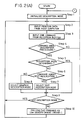
- Fig. 2 comprising Figs. 2(A) and 2(B), is a flowchart of printing control according to the embodiment illustrated in Fig. 1.
- Fig. 3 illustrates a bit map memory for graphic data.
- Fig. 4 illustrates a bit map memory for text data.
- Fig. 5 is a flowchart of printing control according to another embodiment of the present invention.
- Fig. 6 illustrates the internal construction of a laser beam printer according to the present invention.
- Fig. 7 shows exemplary commands.
- Fig. 6 shows a laser beam printer (referred to as "an LBP" hereinafter) according to this embodiment, which is able to register character patterns and form data received from a data source, i.e. a host computer (not shown).
- a data source i.e. a host computer (not shown).
- an LBP 1000 receives and stores the information from a host computer (denoted by numeral 1 in Fig. 1), e.g. character information (character code), form data and macro instructions. According to the information, the LBP 1000 generates character patterns, form patterns, etc., to form an image on a recording medium such as recording paper.
- An operation panel 1012 has a switch, an LED display, etc. arranged thereon.
- a printer control unit 1001 performs overall control of the LBP and analyzes information, such as character information, received from the host computer. The printer control unit 1001 converts the character data into video signals of the corresponding character patterns and sends the video signals to a laser driver 1002.
- the laser driver 1002 is a circuit which drives a semiconductor laser 1003. According to the video signals from the printer control unit 1001, the laser driver 1002 switches on and off the laser beam emission of the semiconductor laser 1003.
- the laser beam 1004 is reflected by a rotary polygon mirror 1005 for scanning the surface of an electrostatic drum 1006.
- An electrostatic latent image of the character patterns is thus formed on the electrostatic drum 1006.
- the latent image is developed by a developer unit 1007 provided near the surface of the electrostatic drum 1006.
- the developed image is transferred to recording paper.
- the recording paper used is of a cutsheet type.
- the cut-sheet recording papers are stored in a paper cassette 1008, which is mounted to the LBP 1000.
- a pick-up roller 1009 and conveying rollers 1010, 1011 feed a cut-sheet recording paper from the cassette 1008 to the electrostatic drum 1006 inside the apparatus.
- a host computer 1 outputs printing data including print data and control codes to a printing apparatus 2.
- the printing apparatus 2 is composed of format control unit 21, an engine control unit 22 and a printer engine unit 23.
- the format control unit 21 is in turn composed of a command analyzing unit 211, a command executing unit 212, and an output control unit 213, and the format control unit 21 comprises a printing control means according to the present invention.
- the printing information from the host computer 1 is stored in a reception buffer 2112, and is analyzed by a printing information processing unit 2111.
- the information processing unit 2111 determines whether the received printing information is a command concerning text description or a command concerning graphic description or a command of another kind.
- Fig. 7(a) shows a representative command for graphic description. If processing unit 2111 encounters a command like that in Fig. 7(A), then graphic description processing is performed. If, on the other hand, processing unit 2111 encounters a command like that in Fig 7(b), which is a representative command for text description, then text description processing is performed.
- Commands not concerning text or graphic description are executed by a command analyzing unit 211.
- a command concerning description is executed by a command executing unit 212.
- text description processing text data is operated by a text description processing unit 2121, and the processed data is serially developed into dot data over a bit map memory 2123.
- graphic description processing graphic data is operated by a graphic description processing unit 2122, and the processed data is serially developed into dot data over a bit map memory 2123.
- the developed dot data in either of the processings is serially sent to an output processing unit 2131 of an output control unit 213.
- the output processing unit 2131 converts the data from the bit map memory 2123 into a video signal.
- Graphic description data is processed to upgrade print quality by a smoothing circuit 2132 before conversion to a video signal.
- the video signal is outputted to the engine control unit 22.
- the output processing unit 2131 also exchanges information, as depicted by the dotted arrow, such as engine control commands and the status of various actions of a printer engine, with the engine control unit 22 in order to adjust the timing of image transfer to the engine control unit 22.
- a CPU 214 controls the overall control system of the format control unit 214, according to the control program of the CPU 214 stored in a ROM 2141.
- the engine control unit 22 controls various printing means of a printer engine unit 23.
- the printer engine unit 23 forms a permanently visible image on recording paper from the image described on the bit map memory according to the printing information received from the host computer.
- Step 1 Before starting the print processing of one page, the description mode is initialized (Step 1).
- the printing data from the host computer 1 is stored in the reception buffer 2112 (Step 2).
- the printing information processing unit 2111 retrieves one command from the reception buffer 2112 (Step 3).
- the printing information processing unit 2111 finds out whether the retrieved command is a command concerning text or graphic description processing (Step 4). If it is a description-concerning command, processing proceeds to Step 5.
- Step 5 it is checked whether the description mode has been determined. If it has been determined, processing proceeds to Step 9 without changing description modes. If it has not been determined, the printing information processing unit 2111 checks whether the retrieved command is a text description command or a graphic description command (Step 6). If it is a text description command, the text description mode is selected (Step 7). If it is a graphic description command, the graphic description mode is selected (Step 8).
- Step 9 it is checked whether the determined description mode is the text mode or the graphic mode. If it is the graphic description mode, processing proceeds to Step 10, where the graphic description processing unit 2122 develops the received graphic description command into dot data on the bit map memory 2123 to describe one page of a low-density (300dpi) image thereon. When the description processing is completed, the procedure returns to Step 2. If, on the other hand, the description mode is the text description mode, the text description processing is performed but first processing from Step 2 to Step 9 is repeated until a paper-discharge command is retrieved.
- Step 4 If it is determined that the retrieved command is not a command concerning the description processing at Step 4, the procedure goes to Step 11, where it is determined whether the command is a paper-discharge command. If it is not a paper-discharge command, the command analyzing unit 211 executes the command (Step 12), and the procedure returns to Step 2.
- Step 11 If it is determined that the command is a paper-discharge command at Step 11, the procedure goes to Step 13, where it is determined whether the mode is the graphic description mode or the text description mode.
- the procedure goes to step 14, where the output processing is performed.
- the output processing unit 2131 exchanges information, such as engine control commands or the status of various actions of the printer engine, with the engine control unit 22 and, thus, adjusts the timing of image transfer to the engine control unit 22.
- the print resolutions at Step 17 and Step 21 are different from each other, and the appropriate resolution is set in output processing.
- the resolution can be changed by known means such as by varying beam clock frequency, and/or paper-feeding speed.
- Step 14 the content of the bit map memory 2123 is smoothed by the smoothing circuit 2134 (Step 15).
- the smoothed signals are converted to video signals to be outputted to the engine control unit 22 (Step 16).
- smoothing-out processing notches of the dot pattern are smoothed out, e.g. by reducing the diameter of the dots, in accordance with known technique such as those described in U.S. Patent No. 4,878,068, the contents of which are incorporated herein by reference.
- the engine control unit 22 performs print processing, i.e. controls various printing means of the printer engine unit 23 (Step 17). Then, the printer engine unit 23 forms a permanently visible image on recording paper and discharges such recording paper (Step 23). When the above-described processing is completed, the procedure returns to Step 1.
- the procedure goes from Step 13 to Step 18, where the text description processing unit 2121 develops dot data at a high-density image (600dpi) from the retrieved text description command, on the bit map memory 2123.
- the capacity of the bit map memory 2123 is not so large as to store an entire page of a high-density image (600dpi).
- the bit map memory 2123 stores, at any one time, only a portion (or band) thereof (e.g., a quarter of the page) defined by a virtual window assumed to move over the page of the printing paper on which the current printing is to be made, as shown in Fig. 4.
- Step 19 the output processing unit 2131 exchanges information, such as engine control commands or the status of various actions of the printer engine, with the engine control unit 22 in order to adjust the timing of image transfer to the engine control unit 22.
- the dot data of the bit map memory 2123 is directly converted to video signals to be outputted to the engine control unit 22.
- the engine control unit 22 performs print processing by controlling various printing means of the printer engine unit 23. Also, the printer engine unit 23 prints a permanently visible image on the printing paper.
- the processing of Steps 18 to 21 is repeated until one page of the printing is completed (Step 22). When it is completed, the printed paper is discharged (Step 23).
- the description mode is selected according to the analysis of inputted information (e.g. expressed in page description language).
- each command retrieved is examined whether it is a text description command or a graphic description command. If the one page of retrieved data are all text description commands, the one page of data are divided into portions to be serially developed as a high-density image (600dpi) on the bit map memory (band processing) and to be serially printed. If the one page of retrieved data includes any number of graphic description commands, the one page of data are developed as a low-density image (300dpi) on the bit map memory. The developed dot data are smoothed for outputting.
- the print density is changed according to the kind of printing. Therefore, if this method is employed, a bit map memory of large capacity is not required.
- Highly-defined printing can be performed by a high-density (600dpi) laser beam printer employing a bit map memory having the same capacity as the bit map memory employed in a conventional printer controller of low-density printing (300dpi).
- An output method comprises the steps of: analyzing the information, e.g. from a host computer, to determine whether the information is text data or graphic data; in the case of text data, dividing one page of data into portions to develop the data as dot patterns of high resolution; and, in the case of graphic data, developing the entire page of data as a dot pattern of low resolution.
- Such divided text description processing does not cause inconvenient delay because the development of text data into dot patterns is quick, compared with that of graphic data and can be completed before the developed dot patterns are printed.
- An output apparatus comprises: an analyzing means for analyzing the information inputted thereto; and a developing means which, according to the analysis by the analyzing means, develops text data as dot patterns of high resolution and graphic data as dot patterns of low density.
Landscapes
- Engineering & Computer Science (AREA)
- General Engineering & Computer Science (AREA)
- Physics & Mathematics (AREA)
- General Physics & Mathematics (AREA)
- Theoretical Computer Science (AREA)
- Dot-Matrix Printers And Others (AREA)
- Record Information Processing For Printing (AREA)
- Editing Of Facsimile Originals (AREA)
Priority Applications (1)
| Application Number | Priority Date | Filing Date | Title |
|---|---|---|---|
| EP98200667A EP0856811B1 (fr) | 1991-04-23 | 1992-04-22 | Appareil de contrôle pour imprimante |
Applications Claiming Priority (2)
| Application Number | Priority Date | Filing Date | Title |
|---|---|---|---|
| JP92306/91 | 1991-04-23 | ||
| JP9230691A JP3015133B2 (ja) | 1991-04-23 | 1991-04-23 | 印刷制御装置及び方法 |
Related Child Applications (1)
| Application Number | Title | Priority Date | Filing Date |
|---|---|---|---|
| EP98200667A Division EP0856811B1 (fr) | 1991-04-23 | 1992-04-22 | Appareil de contrôle pour imprimante |
Publications (3)
| Publication Number | Publication Date |
|---|---|
| EP0510924A2 true EP0510924A2 (fr) | 1992-10-28 |
| EP0510924A3 EP0510924A3 (en) | 1993-03-31 |
| EP0510924B1 EP0510924B1 (fr) | 1998-09-23 |
Family
ID=14050725
Family Applications (2)
| Application Number | Title | Priority Date | Filing Date |
|---|---|---|---|
| EP19920303575 Expired - Lifetime EP0510924B1 (fr) | 1991-04-23 | 1992-04-22 | Méthode de sortie et appareil l'utilisant |
| EP98200667A Expired - Lifetime EP0856811B1 (fr) | 1991-04-23 | 1992-04-22 | Appareil de contrôle pour imprimante |
Family Applications After (1)
| Application Number | Title | Priority Date | Filing Date |
|---|---|---|---|
| EP98200667A Expired - Lifetime EP0856811B1 (fr) | 1991-04-23 | 1992-04-22 | Appareil de contrôle pour imprimante |
Country Status (3)
| Country | Link |
|---|---|
| EP (2) | EP0510924B1 (fr) |
| JP (1) | JP3015133B2 (fr) |
| DE (2) | DE69227062T2 (fr) |
Families Citing this family (3)
| Publication number | Priority date | Publication date | Assignee | Title |
|---|---|---|---|---|
| JPH05229179A (ja) * | 1992-02-21 | 1993-09-07 | Nec Corp | ページプリンタ |
| DE102006033098A1 (de) * | 2006-07-14 | 2008-01-24 | Rebholz, Erich, Dr. | Verfahren und Einrichtung zum Zwischenlagern von Mikroben |
| JP5199727B2 (ja) * | 2008-05-15 | 2013-05-15 | キヤノン株式会社 | 画像処理方法及び画像処理装置とその制御方法 |
Family Cites Families (4)
| Publication number | Priority date | Publication date | Assignee | Title |
|---|---|---|---|---|
| US4752894A (en) * | 1985-12-30 | 1988-06-21 | Deering Michael F | Color plotter controller |
| DE3852457T2 (de) * | 1987-07-31 | 1995-06-14 | Qms Inc | Seitendrucksystem mit virtuellem Speicher. |
| US4992956A (en) * | 1987-10-08 | 1991-02-12 | Advanced Micro Devices, Inc. | Apparatus for assembling data for supply to a scanning output device |
| EP0388160B1 (fr) * | 1989-03-15 | 1997-05-21 | Canon Kabushiki Kaisha | Dispositif de sortie |
-
1991
- 1991-04-23 JP JP9230691A patent/JP3015133B2/ja not_active Expired - Fee Related
-
1992
- 1992-04-22 EP EP19920303575 patent/EP0510924B1/fr not_active Expired - Lifetime
- 1992-04-22 EP EP98200667A patent/EP0856811B1/fr not_active Expired - Lifetime
- 1992-04-22 DE DE1992627062 patent/DE69227062T2/de not_active Expired - Fee Related
- 1992-04-22 DE DE1992632756 patent/DE69232756T2/de not_active Expired - Lifetime
Also Published As
| Publication number | Publication date |
|---|---|
| DE69227062D1 (de) | 1998-10-29 |
| DE69232756D1 (de) | 2002-10-02 |
| DE69232756T2 (de) | 2003-04-10 |
| DE69227062T2 (de) | 1999-03-18 |
| JP3015133B2 (ja) | 2000-03-06 |
| EP0510924A3 (en) | 1993-03-31 |
| EP0856811A1 (fr) | 1998-08-05 |
| JPH04323058A (ja) | 1992-11-12 |
| EP0856811B1 (fr) | 2002-08-28 |
| EP0510924B1 (fr) | 1998-09-23 |
Similar Documents
| Publication | Publication Date | Title |
|---|---|---|
| EP0895184B1 (fr) | Dispositif et méthode de contrôle d'impression pour préparer une mise en page | |
| EP2317753A1 (fr) | Procédé et appareil de commande d'impréssion | |
| EP0575167B1 (fr) | Dispositif de traitement d'information et dispositif de sortie | |
| US6348975B1 (en) | Image processing apparatus, image processing method, and storage medium | |
| EP0727732B1 (fr) | Méthode et dispositif de commande de sortie et produit de programme d'ordinateur | |
| US5567061A (en) | Output apparatus with detachable character storing cartridge | |
| US5406383A (en) | Method and apparatus for outputting a pattern in a selected one of a plurality of output resolutions | |
| US6175426B1 (en) | Printing apparatus and print control method | |
| EP0657844B1 (fr) | Appareil et méthode d'impression | |
| US6504955B2 (en) | Information processing apparatus, information processing method, storage medium, and printing system | |
| US6985260B1 (en) | Apparatus and method for drawing a gradient fill object | |
| US6100996A (en) | Image processing apparatus and method, print control apparatus and method, and printer | |
| US6002848A (en) | Band-based printing control system | |
| US6236755B1 (en) | Output method and apparatus | |
| EP0856811B1 (fr) | Appareil de contrôle pour imprimante | |
| US5778159A (en) | Data outputting with control of number of gradations expressed | |
| EP0864965B1 (fr) | Dispositif de traitement d'information et dispositif de sortie | |
| US7359089B2 (en) | Image processing method and apparatus | |
| US7027170B1 (en) | Printing control system for separation printing | |
| JP3308663B2 (ja) | 画像形成装置 | |
| JP2001096804A (ja) | 画像出力装置及びその制御方法 | |
| JP3576622B2 (ja) | 画像出力装置および方法および印刷システム | |
| JPH10254213A (ja) | 画像形成システム、画像形成方法および記憶媒体 | |
| JP2001002280A (ja) | 画像出力装置及びその制御方法 | |
| JP3327744B2 (ja) | 記録装置及びその方法及びコンピュータ制御装置 |
Legal Events
| Date | Code | Title | Description |
|---|---|---|---|
| PUAI | Public reference made under article 153(3) epc to a published international application that has entered the european phase |
Free format text: ORIGINAL CODE: 0009012 |
|
| AK | Designated contracting states |
Kind code of ref document: A2 Designated state(s): DE FR GB IT |
|
| PUAL | Search report despatched |
Free format text: ORIGINAL CODE: 0009013 |
|
| AK | Designated contracting states |
Kind code of ref document: A3 Designated state(s): DE FR GB IT |
|
| 17P | Request for examination filed |
Effective date: 19930817 |
|
| 17Q | First examination report despatched |
Effective date: 19960503 |
|
| GRAG | Despatch of communication of intention to grant |
Free format text: ORIGINAL CODE: EPIDOS AGRA |
|
| GRAG | Despatch of communication of intention to grant |
Free format text: ORIGINAL CODE: EPIDOS AGRA |
|
| GRAH | Despatch of communication of intention to grant a patent |
Free format text: ORIGINAL CODE: EPIDOS IGRA |
|
| GRAH | Despatch of communication of intention to grant a patent |
Free format text: ORIGINAL CODE: EPIDOS IGRA |
|
| GRAA | (expected) grant |
Free format text: ORIGINAL CODE: 0009210 |
|
| AK | Designated contracting states |
Kind code of ref document: B1 Designated state(s): DE FR GB IT |
|
| REF | Corresponds to: |
Ref document number: 69227062 Country of ref document: DE Date of ref document: 19981029 |
|
| ET | Fr: translation filed | ||
| PLBE | No opposition filed within time limit |
Free format text: ORIGINAL CODE: 0009261 |
|
| STAA | Information on the status of an ep patent application or granted ep patent |
Free format text: STATUS: NO OPPOSITION FILED WITHIN TIME LIMIT |
|
| 26N | No opposition filed | ||
| REG | Reference to a national code |
Ref country code: GB Ref legal event code: IF02 |
|
| PGFP | Annual fee paid to national office [announced via postgrant information from national office to epo] |
Ref country code: GB Payment date: 20050408 Year of fee payment: 14 |
|
| PGFP | Annual fee paid to national office [announced via postgrant information from national office to epo] |
Ref country code: FR Payment date: 20050421 Year of fee payment: 14 |
|
| PGFP | Annual fee paid to national office [announced via postgrant information from national office to epo] |
Ref country code: DE Payment date: 20050620 Year of fee payment: 14 |
|
| PG25 | Lapsed in a contracting state [announced via postgrant information from national office to epo] |
Ref country code: GB Free format text: LAPSE BECAUSE OF NON-PAYMENT OF DUE FEES Effective date: 20060422 |
|
| PGFP | Annual fee paid to national office [announced via postgrant information from national office to epo] |
Ref country code: IT Payment date: 20060430 Year of fee payment: 15 |
|
| PG25 | Lapsed in a contracting state [announced via postgrant information from national office to epo] |
Ref country code: DE Free format text: LAPSE BECAUSE OF NON-PAYMENT OF DUE FEES Effective date: 20061101 |
|
| GBPC | Gb: european patent ceased through non-payment of renewal fee |
Effective date: 20060422 |
|
| REG | Reference to a national code |
Ref country code: FR Ref legal event code: ST Effective date: 20061230 |
|
| PG25 | Lapsed in a contracting state [announced via postgrant information from national office to epo] |
Ref country code: FR Free format text: LAPSE BECAUSE OF NON-PAYMENT OF DUE FEES Effective date: 20060502 |
|
| PG25 | Lapsed in a contracting state [announced via postgrant information from national office to epo] |
Ref country code: IT Free format text: LAPSE BECAUSE OF NON-PAYMENT OF DUE FEES Effective date: 20070422 |