EP0511111A1 - Elektrische Verbindung und Gehäuse für elektrische Bauteile mit einer solchen Verbindung - Google Patents
Elektrische Verbindung und Gehäuse für elektrische Bauteile mit einer solchen Verbindung Download PDFInfo
- Publication number
- EP0511111A1 EP0511111A1 EP92401172A EP92401172A EP0511111A1 EP 0511111 A1 EP0511111 A1 EP 0511111A1 EP 92401172 A EP92401172 A EP 92401172A EP 92401172 A EP92401172 A EP 92401172A EP 0511111 A1 EP0511111 A1 EP 0511111A1
- Authority
- EP
- European Patent Office
- Prior art keywords
- cage
- screw
- bar
- wire
- support
- Prior art date
- Legal status (The legal status is an assumption and is not a legal conclusion. Google has not performed a legal analysis and makes no representation as to the accuracy of the status listed.)
- Granted
Links
- 238000003780 insertion Methods 0.000 claims abstract description 25
- 238000003825 pressing Methods 0.000 claims abstract description 3
- 230000037431 insertion Effects 0.000 claims description 22
- 230000003100 immobilizing effect Effects 0.000 claims description 3
- 239000011810 insulating material Substances 0.000 claims description 3
- 239000002184 metal Substances 0.000 claims description 3
- 238000000926 separation method Methods 0.000 claims description 3
- 238000006243 chemical reaction Methods 0.000 claims description 2
- 238000009331 sowing Methods 0.000 claims 1
- 239000004020 conductor Substances 0.000 description 2
- 239000000470 constituent Substances 0.000 description 2
- 238000000034 method Methods 0.000 description 2
- 238000013459 approach Methods 0.000 description 1
- 239000011324 bead Substances 0.000 description 1
- 230000000295 complement effect Effects 0.000 description 1
- 238000005520 cutting process Methods 0.000 description 1
- 238000006073 displacement reaction Methods 0.000 description 1
- 230000000694 effects Effects 0.000 description 1
- 238000004519 manufacturing process Methods 0.000 description 1
- 238000000465 moulding Methods 0.000 description 1
- 230000002093 peripheral effect Effects 0.000 description 1
Images

Classifications
-
- H—ELECTRICITY
- H01—ELECTRIC ELEMENTS
- H01R—ELECTRICALLY-CONDUCTIVE CONNECTIONS; STRUCTURAL ASSOCIATIONS OF A PLURALITY OF MUTUALLY-INSULATED ELECTRICAL CONNECTING ELEMENTS; COUPLING DEVICES; CURRENT COLLECTORS
- H01R4/00—Electrically-conductive connections between two or more conductive members in direct contact, i.e. touching one another; Means for effecting or maintaining such contact; Electrically-conductive connections having two or more spaced connecting locations for conductors and using contact members penetrating insulation
- H01R4/28—Clamped connections, spring connections
- H01R4/30—Clamped connections, spring connections utilising a screw or nut clamping member
- H01R4/36—Conductive members located under tip of screw
- H01R4/363—Conductive members located under tip of screw with intermediate part between tip and conductive member
-
- H—ELECTRICITY
- H01—ELECTRIC ELEMENTS
- H01R—ELECTRICALLY-CONDUCTIVE CONNECTIONS; STRUCTURAL ASSOCIATIONS OF A PLURALITY OF MUTUALLY-INSULATED ELECTRICAL CONNECTING ELEMENTS; COUPLING DEVICES; CURRENT COLLECTORS
- H01R4/00—Electrically-conductive connections between two or more conductive members in direct contact, i.e. touching one another; Means for effecting or maintaining such contact; Electrically-conductive connections having two or more spaced connecting locations for conductors and using contact members penetrating insulation
- H01R4/28—Clamped connections, spring connections
- H01R4/30—Clamped connections, spring connections utilising a screw or nut clamping member
- H01R4/302—Clamped connections, spring connections utilising a screw or nut clamping member having means for preventing loosening of screw or nut, e.g. vibration-proof connection
-
- H—ELECTRICITY
- H01—ELECTRIC ELEMENTS
- H01R—ELECTRICALLY-CONDUCTIVE CONNECTIONS; STRUCTURAL ASSOCIATIONS OF A PLURALITY OF MUTUALLY-INSULATED ELECTRICAL CONNECTING ELEMENTS; COUPLING DEVICES; CURRENT COLLECTORS
- H01R4/00—Electrically-conductive connections between two or more conductive members in direct contact, i.e. touching one another; Means for effecting or maintaining such contact; Electrically-conductive connections having two or more spaced connecting locations for conductors and using contact members penetrating insulation
- H01R4/28—Clamped connections, spring connections
- H01R4/30—Clamped connections, spring connections utilising a screw or nut clamping member
- H01R4/308—Conductive members located parallel to axis of screw
Definitions
- the invention relates to electrical connections, of the screw type and to axial connection, and electrical appliance boxes comprising at least one such connection.
- French Patent 2,574,598 describes an electrical connection, in particular a miniature one, by means of which an electrically conductive wire is immobilized against a wire support wall of a conductive strip of an electrical appliance, such as for example a junction block, between this support wall and an internal wire support wall of a cage which surrounds the strip, under the action of a clamping screw which is screwed into the cage and which bears against the bar on the other side of the latter relative to the two wire support walls.
- the clamping screw is disposed obliquely in the cage relative to the wire support wall of this cage and comes directly into pressure by its end on the bar, it is also laterally pressed against a lateral support element provided for this effect on the cage.
- this box when the connection is housed in a box, for example a connector, a terminal block or any other electrical device, this box generally includes a wire introduction opening for connection and an opening for 'access to the clamping screw which are separate.
- connection mentioned above is more specifically intended for devices having housings where the introduction opening and the access opening for the same connection have respective oblique orientations, one with respect to the other, each opening opening for example onto a different face of the housing.
- the invention therefore provides an electrical connection which, derived from that in the French patent mentioned above, for connecting a conductive wire with a conductive bar of an electrical device by immobilizing the wire against a support element provided on the bar, between this element and another support element, forming the bottom and at least approximately parallel, of a cage which surrounds the bar and this under the action of a clamping screw screwed into a cage element , located opposite the support element forming the bottom, and pressing at the end against the support element of the bar on the other side thereof relative to the support element of the cage, this screw being arranged obliquely with respect to these bar and cage support elements, against at least one lateral support structure opposing the transverse reaction of repulsion of the end of the screw by the bar when tightening, in the cage, the supporting elements of the bar rette and that of the cage delimiting between them a wire insertion conduit obliquely oriented relative to the screw.
- the support element of the cage is extended by an extension serving as a wire guide which projects out of the cage on one of the sides where the wire insertion conduit opens.
- the invention also provides an electrical appliance box internally comprising at least one connection as defined above, in a body of insulating material inside which the bar, the screw and the cage are housed, the bar being therein. immobilized, while the cage is capable of guided displacements there, oriented along the axis of the screw and occasioned by the maneuver of the latter, between two positions respectively corresponding one to maximum approximation of the wire support elements of the bar and the bottom of the cage and the other at a maximum distance from these elements.
- the housing comprises an arrangement for immobilizing in translation for a clamping screw allowing the operation of a screw via the head of this screw through an access opening of the housing.
- a wire introduction conduit having an orientation at least approximately parallel to the direction of cage movement defined by the screw axis opens, this introduction conduit being closed by the wire guide extension of the cage considered which penetrates there obliquely to the vicinity of a wall of this conduit with which it provides relative continuity for guiding, in the insertion conduit of the cage, a wire pushed through said conduit d introduction since the opening of the latter.
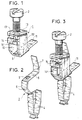
- Figure 1 shows an example of a screw cage for connection according to the invention.
- FIG. 2 shows an example of a strip for connection according to the invention.
- FIG. 3 shows a connection formed using the screw cage and the bar according to FIGS. 1 and 2.
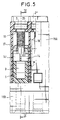
- Figure 4 shows a section along IV-IV of an apparatus housing having connections as defined in connection with the previous figures.
- FIG. 5 shows a partial section along V-V of a portion of the housing presented in FIG. 4.
- the electrical connection comprises a cage 1 provided with a clamping screw 2 which are shown in FIG. 1 and a conductive bar 3, an embodiment of which is given in FIG. 2.
- Cage 1 and bar 3 are intended to cooperate with each other to firstly immobilize one end of the conductive wire between them and on the other hand to ensure the electrical connection of this conductive wire with an electrical appliance by the 'Intermediate of a connection member 4 capable of being carried by the bar as shown in Figures 2 to 5, or possibly by the cage, this connection member 4 being for example of clamp type, as shown here.
- the cage 1 and the assembly formed by the bar 3 and by the connection member 4, are here assumed to be made by cutting and folding from metal blanks according to techniques well known in the field, such a cage can also be obtained by other techniques and for example by molding.
- the bar 3 proper is here supposed to consist of a strip, of resilient metal which is a good conductor, of rectangular shape, extending a common part uniting the two jaws of the clamp which here constitutes the connection member 4; this band of rectangular appearance comprises an element, called a support element, 5 against a wall from which it is intended to apply the conductive wire to be connected.
- This support element 5 is here connected to the common part connecting the clamp jaws by an element, called a wire stop, 6 against which the end of a conductive wire to be connected should normally come up against.
- This stop element 6 is here composed of two successive portions which are obliquely positioned by transverse folding each with respect to the other and with respect to the element which it extends, that is to say one with respect to the element d 'support 5 and the other relative to the connection member 4.
- the support element 5 also continues on the other side of the stop element by an element 7, called a wire guide, also here assumed to consist of two successive portions obliquely positioned by transverse folding one relative to the other and relative to the support element 5 that one of them extends.
- a wire guide also here assumed to consist of two successive portions obliquely positioned by transverse folding one relative to the other and relative to the support element 5 that one of them extends.
- a relief 8 is provided to serve as a support at the end of the screw 2, on the support element 5.
- This relief 8 is here produced in the form of a tongue partially cut from the strip forming the bar and then folded.
- the cage 1 is intended to surround the bar 3 at the level of the support element 5.
- This cage 1 is produced by folding around a central element 9 intended to serve as an internal support at the bottom of the cage for the wire to be connected.
- the support element 9 is provided arranged obliquely to the rest of the cage and at least approximately parallel to the support element 5 of the bar 3, when the connection which comprises them is assembled, so as to delimit a wire insertion conduit with this support element 5 and at possibly come to press against him under the action of screw 2.
- the support element 9 is identically extended on two of its parallel edges by two strip elements 10 and 10 ′ folded in opposite directions so as to be perpendicular to it and parallel to each other, when the cage is made.
- the support element 9 is also extended by an extension 11, called a wire guide, projecting out of the cage, here in the same plane as the element 9 itself, or possibly with a slightly different angulation.
- an extension 11 called a wire guide, projecting out of the cage, here in the same plane as the element 9 itself, or possibly with a slightly different angulation.
- the two strip elements 10, 10 ′ are interconnected by at least one and here two elements 13, 13 ′ which are perpendicularly folded towards each other and each with respect to the strip element 10 or 10 ′ from which it originates to form with the other a single connecting element, having a double thickness, where a tapped bore is provided for the screw 2.
- the latter enters the cage through this tapped bore to come to bear against the relief 8 on the bar 3, it also bears against a support structure composed of two projections 14, 14 ′ each carried laterally by one of the elements of strip 10 or 10 ′ with respect to which it is perpendicularly folded down so as to serve as a lateral stop for the screw 2, the body of which is preferably made smooth at this level, ie here towards the conical end of support of this screw on the bar 3 .
- the bar 3 is mounted in the cage 1 so that the support element 5 comes to be located between the elements 10, 10 ′ parallel to the support element 9 with which it determines the wire insertion conduit .
- the guide element 7 is positioned along the screw 2 on the side of the end of the wire insertion conduit where the wire guide extension 11 is located, the element wire stop 6 placed at the other end of the insertion duct which it closes, in the vicinity of the projections 14, 14 ′.
- FIGS. 4 and 5 An example of use of an electrical connection according to the invention in an apparatus is shown in FIGS. 4 and 5, it relates to a connector comprising a double row of such connections in a housing made of insulating material, here produced in two nested parts 15A, 15B.
- the two connections shown in Figure 4 each include a cage 1 or 1 ′, a screw 2 or 2 ′ and a bar 3 or 3 ′ housed in the housing 15A, 15B so that the screws 2 and 2 ′ are parallel and each the along one of the edges of the housing.
- Each bar is individually immobilized in the housing, for example after depression of the part 15A on the part 15B thanks to the complementary shapes of these bars and of the housing of the housing where they are positioned, as is usual in the field.
- Each cage encircles the corresponding bar as indicated above and is capable of moving relative to it in a translational movement along the axis of the corresponding tightening screw inside a rectilinear guide formed in the example proposed by the external wall of the housing, such as 16 - FIG. 4 -, which adjoins the associated screw, ie here 2, and by parallel guide walls, such as 17 and 18 - FIG. 5 -, which are perpendicular to this external wall in the housing and which separate the connections from each other.
- Each screw is immobilized in translation on the one hand because of the support of its end against a relief provided for this purpose on the support element of each bar, such that the relief 8 on the support element 5 for the screw, and on the other hand due to the partial imprisonment of its head in an arrangement, such as 17 for the screw 2, and here molded in the part 15A of the housing.
- each housing opens on the one hand by a conduit, such as 19, for the passage of the screw body towards the rectilinear guide where the associated cage moves.
- a conduit such as 19, for the passage of the screw body towards the rectilinear guide where the associated cage moves.
- an access opening which formed, such as 20, in an outer wall of the housing and here in part 15A, initially allows the insertion of a screw, then later its operation from the outside of this case.
- the imprisonment of a screw head in an arrangement housing 17 is obtained for example by means of a peripheral bead, such as 21, formed at the edge of the opening 20.
- a peripheral bead such as 21, formed at the edge of the opening 20.
- the operation of a screw, such as 2 alternately allows the support walls 5 and 9 of the bar and the cage associated with this screw to be moved apart then brought closer between a position of maximum approximation and a position of maximum separation.
- an introduction conduit such as 23 - Figure 4 -, which opens near the opening 20 for access to the screw assigned to this connection, this introduction conduit here being parallel to the direction of movement of the cage of this connection.
- Each introduction conduit 23 is for example bordered on two sides by parallel walls such as 17 and 18 between which the associated cage moves and on a third side by a wall 24 integral with one of the constituent parts of the housing, here Part 15A.
- this wall is common to two parallel connections transversely arranged in the housing, a fourth wall of the introduction conduit is here formed by an element, such as 7, of bar which, projecting out of the wire insertion conduit formed between support walls 5 and 9 of bar and cage, is pressed against the screw and the cage portion where this screw is positioned.
- the element 7 is obliquely folded towards the screw body, in the direction of the head of this screw, and it pushes the cage, on which it presses, against the wall 16 of the housing along which it slides and towards the support element 5 of the bar, when the distance between the support elements 5 and 9 of this bar and of the cage differs from their maximum distance, to preposition the cage in its housing before connecting a wire.
- the introduction conduit associated with a connection communicates with the insertion conduit provided for this connection and it is closed by the extension 11 which comprises the corresponding wall 9 of cage support.
- the inclination of the extension 11 directs the end of the conductor, then pushed, towards the inside of the insertion conduit and until it stops against the wire stop element, such as 6, which terminates this conduit. 'insertion.
Landscapes
- Connections By Means Of Piercing Elements, Nuts, Or Screws (AREA)
- Connections Arranged To Contact A Plurality Of Conductors (AREA)
- Insertion, Bundling And Securing Of Wires For Electric Apparatuses (AREA)
- Details Of Indoor Wiring (AREA)
Applications Claiming Priority (2)
| Application Number | Priority Date | Filing Date | Title |
|---|---|---|---|
| FR9105191A FR2675954B1 (fr) | 1991-04-26 | 1991-04-26 | Connexion electrique et boitier d'appareil electrique comportant une telle connexion. |
| FR9105191 | 1991-04-26 |
Publications (2)
| Publication Number | Publication Date |
|---|---|
| EP0511111A1 true EP0511111A1 (de) | 1992-10-28 |
| EP0511111B1 EP0511111B1 (de) | 1994-11-02 |
Family
ID=9412305
Family Applications (1)
| Application Number | Title | Priority Date | Filing Date |
|---|---|---|---|
| EP92401172A Expired - Lifetime EP0511111B1 (de) | 1991-04-26 | 1992-04-23 | Elektrische Verbindung und Gehäuse für elektrische Bauteile mit einer solchen Verbindung |
Country Status (7)
| Country | Link |
|---|---|
| US (1) | US5192234A (de) |
| EP (1) | EP0511111B1 (de) |
| JP (1) | JP3037819B2 (de) |
| CA (1) | CA2067079C (de) |
| DE (1) | DE69200607T2 (de) |
| ES (1) | ES2065142T3 (de) |
| FR (1) | FR2675954B1 (de) |
Cited By (4)
| Publication number | Priority date | Publication date | Assignee | Title |
|---|---|---|---|---|
| EP0536523A3 (en) * | 1991-10-09 | 1993-08-11 | Ria Electronic Albert Metz | Terminal |
| FR2708385A1 (fr) * | 1993-07-28 | 1995-02-03 | Entrelec Sa | Bloc de jonction électrique. |
| WO1995006340A1 (de) * | 1993-08-27 | 1995-03-02 | Contact Gmbh Elektrische Bauelemente | Kontakt- und klemmvorrichtung für elektrische steckverbinder |
| FR2737048A1 (fr) * | 1995-07-18 | 1997-01-24 | Lmi Composants | Element de connexion a connexion axiale pour conducteur electrique |
Families Citing this family (29)
| Publication number | Priority date | Publication date | Assignee | Title |
|---|---|---|---|---|
| DE4401724C2 (de) * | 1994-01-21 | 1996-09-12 | Kopp Heinrich Ag | Vorrichtung zur Frontverdrahtung von elektrischen Geräten, insbesondere von Reiheneinbaugeräten, Steckdosen, Schaltern |
| GB9408326D0 (en) * | 1994-04-27 | 1994-06-15 | Amp Great Britain | Electrical connector for conductive leads |
| US5592989A (en) * | 1994-04-28 | 1997-01-14 | Landis & Gyr Powers, Inc. | Electronic thermostat having high and low voltage control capability |
| DE9410614U1 (de) * | 1994-07-01 | 1994-08-11 | Weidmüller Interface GmbH & Co, 32760 Detmold | Verbinder für elektrische Bus-Leiter |
| US5741073A (en) * | 1995-09-18 | 1998-04-21 | Kaye Instruments, Inc. | Uniform temperature reference apparatus for use with modular terminal block |
| DE19545451A1 (de) * | 1995-12-06 | 1997-06-12 | Weidmueller Interface | Ein- oder mehrreihige Leiterplattenklemme |
| US6048230A (en) * | 1996-11-25 | 2000-04-11 | Nec Corporation | Contact and high-density connector using the same |
| DE29709112U1 (de) * | 1997-05-23 | 1997-07-31 | Siemens AG, 80333 München | Rahmenklemme zum Anschluß elektrischer Leitungen |
| DE59811956D1 (de) * | 1997-06-21 | 2004-10-21 | Acorn Cardiovascular Inc | Beutel zur wenigstens teilweisen umfassung eines herzens |
| DE19813753B4 (de) * | 1998-03-27 | 2005-03-24 | Abb Patent Gmbh | Kontaktklemme |
| DE20200973U1 (de) * | 2002-01-24 | 2003-05-28 | Weidmüller Interface GmbH & Co., 32760 Detmold | Anschlußklemmenleiste |
| DE20218750U1 (de) | 2002-12-04 | 2003-02-06 | STOCKO Contact GmbH & Co. KG, 42327 Wuppertal | Steckkontaktelement, Kontaktiereinheit und Stecker |
| GB2427314A (en) * | 2005-06-15 | 2006-12-20 | Stephen Martin | Electrical connector which can be wired externally |
| US7249963B2 (en) * | 2005-07-11 | 2007-07-31 | Bals Elektrotechnik Gmbh & Co. Kg | Screwless connection frame terminal |
| DE102006016354A1 (de) * | 2006-04-05 | 2007-10-18 | Mc Technology Gmbh | Klemmenblock zum Anschließen von elektrischen Leitern |
| DE102007009448B4 (de) * | 2007-02-23 | 2009-02-26 | Phoenix Contact Gmbh & Co. Kg | Elektrisch leitendes Steckkontaktelement |
| DE202007009351U1 (de) * | 2007-07-04 | 2007-09-06 | Lapp Engineering & Co. | Steckverbinder mit Schraubanschluss |
| US20110294363A1 (en) * | 2007-10-31 | 2011-12-01 | Anytek Technology Corporation, Ltd. | Terminal table fastener |
| DE102007057082A1 (de) * | 2007-11-21 | 2009-05-28 | Newfrey Llc, Newark | Kontaktiereinheit, Befestigungsverfahren und Schraubwerkzeug zur Durchführung des Verfahrens |
| DE102007058730B4 (de) * | 2007-12-06 | 2010-06-24 | Phoenix Contact Gmbh & Co. Kg | Adapter mit einem Kontaktteil, elektrische Verbindungsklemme oder elektrisches Gerät und Verwendung des Adapters |
| US7946895B2 (en) * | 2008-04-21 | 2011-05-24 | Newfrey Llc | Internally threaded nut with a collar held captive in a nut holding section |
| DE102008020511A1 (de) * | 2008-04-23 | 2009-11-05 | Mc Technology Gmbh | Kontaktelement für eine Anschlussklemme, Anschlussklemme und Steckbrücke für ein Kontaktelement |
| US7909633B1 (en) * | 2009-09-15 | 2011-03-22 | Fisher-Rosemount Systems, Inc. | Wire connection apparatus |
| CN202076511U (zh) * | 2010-11-01 | 2011-12-14 | 洛克威尔自动控制技术股份有限公司 | 接线端组件 |
| CN203839613U (zh) * | 2014-05-26 | 2014-09-17 | 泰科电子(上海)有限公司 | 电连接器 |
| US9419352B2 (en) * | 2014-07-23 | 2016-08-16 | GE Lighting Solutions, LLC | Terminal block with ground strap, spring force terminals, and screw lug terminal |
| CN106329174B (zh) * | 2015-06-18 | 2024-05-10 | 连展科技电子(昆山)有限公司 | 壁挂架组件及其夹线型连接器 |
| CN106654631A (zh) * | 2017-02-22 | 2017-05-10 | 云南电网有限责任公司带电作业分公司 | 一种缘操作杆法带电作业用压接型10kV耐张线夹 |
| EP4117119A1 (de) * | 2021-07-08 | 2023-01-11 | Sacopa, S.A.U. | Elektrischer steckverbinder |
Citations (4)
| Publication number | Priority date | Publication date | Assignee | Title |
|---|---|---|---|---|
| DE1903220B1 (de) * | 1969-01-23 | 1970-10-08 | Siemens Ag | Klemme mit rahmenfoermigem Klemmenkoerper |
| US4006323A (en) * | 1975-05-21 | 1977-02-01 | Allen-Bradley Company | Electrical terminal structure |
| DE8534698U1 (de) * | 1984-12-12 | 1986-02-06 | CGEE-Alsthom, Levallois-Perret | Schraubklemme |
| US4810212A (en) * | 1987-08-10 | 1989-03-07 | Connectron, Inc. | Terminal blocks for one-side wire entry and screw access |
Family Cites Families (1)
| Publication number | Priority date | Publication date | Assignee | Title |
|---|---|---|---|---|
| FR1363909A (fr) * | 1963-02-20 | 1964-06-19 | Alkan & Sinay | Borne de métal pour connexions électriques |
-
1991
- 1991-04-26 FR FR9105191A patent/FR2675954B1/fr not_active Expired - Fee Related
-
1992
- 1992-04-23 EP EP92401172A patent/EP0511111B1/de not_active Expired - Lifetime
- 1992-04-23 DE DE69200607T patent/DE69200607T2/de not_active Expired - Fee Related
- 1992-04-23 ES ES92401172T patent/ES2065142T3/es not_active Expired - Lifetime
- 1992-04-24 US US07/873,226 patent/US5192234A/en not_active Expired - Fee Related
- 1992-04-24 CA CA002067079A patent/CA2067079C/fr not_active Expired - Fee Related
- 1992-04-24 JP JP4106723A patent/JP3037819B2/ja not_active Expired - Lifetime
Patent Citations (4)
| Publication number | Priority date | Publication date | Assignee | Title |
|---|---|---|---|---|
| DE1903220B1 (de) * | 1969-01-23 | 1970-10-08 | Siemens Ag | Klemme mit rahmenfoermigem Klemmenkoerper |
| US4006323A (en) * | 1975-05-21 | 1977-02-01 | Allen-Bradley Company | Electrical terminal structure |
| DE8534698U1 (de) * | 1984-12-12 | 1986-02-06 | CGEE-Alsthom, Levallois-Perret | Schraubklemme |
| US4810212A (en) * | 1987-08-10 | 1989-03-07 | Connectron, Inc. | Terminal blocks for one-side wire entry and screw access |
Cited By (4)
| Publication number | Priority date | Publication date | Assignee | Title |
|---|---|---|---|---|
| EP0536523A3 (en) * | 1991-10-09 | 1993-08-11 | Ria Electronic Albert Metz | Terminal |
| FR2708385A1 (fr) * | 1993-07-28 | 1995-02-03 | Entrelec Sa | Bloc de jonction électrique. |
| WO1995006340A1 (de) * | 1993-08-27 | 1995-03-02 | Contact Gmbh Elektrische Bauelemente | Kontakt- und klemmvorrichtung für elektrische steckverbinder |
| FR2737048A1 (fr) * | 1995-07-18 | 1997-01-24 | Lmi Composants | Element de connexion a connexion axiale pour conducteur electrique |
Also Published As
| Publication number | Publication date |
|---|---|
| JP3037819B2 (ja) | 2000-05-08 |
| JPH07192780A (ja) | 1995-07-28 |
| ES2065142T3 (es) | 1995-02-01 |
| FR2675954B1 (fr) | 1993-07-02 |
| FR2675954A1 (fr) | 1992-10-30 |
| CA2067079A1 (fr) | 1992-10-27 |
| EP0511111B1 (de) | 1994-11-02 |
| DE69200607T2 (de) | 1995-03-09 |
| CA2067079C (fr) | 2002-07-09 |
| US5192234A (en) | 1993-03-09 |
| DE69200607D1 (de) | 1994-12-08 |
Similar Documents
| Publication | Publication Date | Title |
|---|---|---|
| CA2067079C (fr) | Connexion electrique et boitier d'appareil electrique comportant une telle connexion | |
| CA1290034C (fr) | Agencement de connexion a fente denudante pour fil electrique | |
| EP0271413A1 (de) | Isolationsverschiebungssteckverbinder für Einzelleiterkabel | |
| EP0867973B1 (de) | Elektrische Verbindungsanordnung und Modul insbesondere Verbindungsmodul mit einer solchen Verbindungsanordnung | |
| CA1245736A (fr) | Connexion electrique vissee | |
| FR2696052A1 (fr) | Boîtier électrique à passage étanche d'un câble d'alimentation. | |
| FR2775845A1 (fr) | Boitier etanche d'appareillage a acces pour cable | |
| EP0381101A1 (de) | Verbindungseinrichtung für Koaxialkabel und entsprechender Verbindungsmodul, insbesondere Verbindungsblock | |
| FR2782196A1 (fr) | Dispositif de connexion a fente denudante pour fil electrique | |
| FR2611092A1 (fr) | Agencement de raccordement electrique pour fils rigides et souples | |
| EP0251909B2 (de) | Verbindungselement für ein elektrisches Monoleiterkabel zur axialen Verbindung | |
| EP0881709B1 (de) | Geschlitzte Anschlussklemme für eine Verbindungsanordnung für mindestens eine elektrische Leiter | |
| FR2782195A1 (fr) | Piece de connexion auto-denudante | |
| FR2642570A1 (fr) | Agencement de raccordement pour extremite de cable coaxial et bloc de jonction dote d'un tel agencement | |
| FR2661046A1 (fr) | Dispositif d'interconnexion permettant de raccorder deux cables electriques non denudes. | |
| EP0744088A1 (de) | Elektrische stecker in englischer ausführung | |
| FR2809872A1 (fr) | Dispositif de liaison electrique pour organe de contact electrique male et element de boitier destine a recevoir un tel dispositif | |
| FR2762086A1 (fr) | Dispositif pour la fixation de capteurs | |
| FR2738959A1 (fr) | Boite de raccordement pour un reseau de donnees | |
| FR2816764A1 (fr) | Dispositif de raccordement pour deux cables electriques | |
| FR2567689A1 (fr) | Pince a denuder | |
| FR2611406A1 (fr) | Agencement de connexion pour appareillage electrique | |
| FR2618607A1 (fr) | Cosse de batterie d'accumulateur | |
| BE1010456A3 (fr) | Boite de raccordement pour un reseau de donnees. | |
| FR2612000A1 (fr) | Borne de derivation |
Legal Events
| Date | Code | Title | Description |
|---|---|---|---|
| PUAI | Public reference made under article 153(3) epc to a published international application that has entered the european phase |
Free format text: ORIGINAL CODE: 0009012 |
|
| AK | Designated contracting states |
Kind code of ref document: A1 Designated state(s): BE DE ES FR GB IT |
|
| 17P | Request for examination filed |
Effective date: 19921121 |
|
| 17Q | First examination report despatched |
Effective date: 19940421 |
|
| GRAA | (expected) grant |
Free format text: ORIGINAL CODE: 0009210 |
|
| AK | Designated contracting states |
Kind code of ref document: B1 Designated state(s): BE DE ES FR GB IT |
|
| ITF | It: translation for a ep patent filed | ||
| REF | Corresponds to: |
Ref document number: 69200607 Country of ref document: DE Date of ref document: 19941208 |
|
| GBT | Gb: translation of ep patent filed (gb section 77(6)(a)/1977) |
Effective date: 19941122 |
|
| REG | Reference to a national code |
Ref country code: ES Ref legal event code: FG2A Ref document number: 2065142 Country of ref document: ES Kind code of ref document: T3 |
|
| PLBE | No opposition filed within time limit |
Free format text: ORIGINAL CODE: 0009261 |
|
| STAA | Information on the status of an ep patent application or granted ep patent |
Free format text: STATUS: NO OPPOSITION FILED WITHIN TIME LIMIT |
|
| 26N | No opposition filed | ||
| REG | Reference to a national code |
Ref country code: GB Ref legal event code: IF02 |
|
| REG | Reference to a national code |
Ref country code: FR Ref legal event code: CJ Ref country code: FR Ref legal event code: CD Ref country code: FR Ref legal event code: CA |
|
| PGFP | Annual fee paid to national office [announced via postgrant information from national office to epo] |
Ref country code: ES Payment date: 20080428 Year of fee payment: 17 Ref country code: DE Payment date: 20080411 Year of fee payment: 17 |
|
| PGFP | Annual fee paid to national office [announced via postgrant information from national office to epo] |
Ref country code: BE Payment date: 20080513 Year of fee payment: 17 Ref country code: IT Payment date: 20080419 Year of fee payment: 17 |
|
| PGFP | Annual fee paid to national office [announced via postgrant information from national office to epo] |
Ref country code: FR Payment date: 20080325 Year of fee payment: 17 |
|
| PGFP | Annual fee paid to national office [announced via postgrant information from national office to epo] |
Ref country code: GB Payment date: 20080417 Year of fee payment: 17 |
|
| BERE | Be: lapsed |
Owner name: S.A. *ENTRELEC Effective date: 20090430 |
|
| GBPC | Gb: european patent ceased through non-payment of renewal fee |
Effective date: 20090423 |
|
| REG | Reference to a national code |
Ref country code: FR Ref legal event code: ST Effective date: 20091231 |
|
| PG25 | Lapsed in a contracting state [announced via postgrant information from national office to epo] |
Ref country code: DE Free format text: LAPSE BECAUSE OF NON-PAYMENT OF DUE FEES Effective date: 20091103 |
|
| PG25 | Lapsed in a contracting state [announced via postgrant information from national office to epo] |
Ref country code: GB Free format text: LAPSE BECAUSE OF NON-PAYMENT OF DUE FEES Effective date: 20090423 Ref country code: FR Free format text: LAPSE BECAUSE OF NON-PAYMENT OF DUE FEES Effective date: 20091222 |
|
| PG25 | Lapsed in a contracting state [announced via postgrant information from national office to epo] |
Ref country code: BE Free format text: LAPSE BECAUSE OF NON-PAYMENT OF DUE FEES Effective date: 20090430 |
|
| REG | Reference to a national code |
Ref country code: ES Ref legal event code: FD2A Effective date: 20090424 |
|
| PG25 | Lapsed in a contracting state [announced via postgrant information from national office to epo] |
Ref country code: ES Free format text: LAPSE BECAUSE OF NON-PAYMENT OF DUE FEES Effective date: 20090424 |
|
| PG25 | Lapsed in a contracting state [announced via postgrant information from national office to epo] |
Ref country code: IT Free format text: LAPSE BECAUSE OF NON-PAYMENT OF DUE FEES Effective date: 20090423 |