EP0511196A1 - Dispositif pour le transport et la séparation de tranches des balles de tabac - Google Patents
Dispositif pour le transport et la séparation de tranches des balles de tabac Download PDFInfo
- Publication number
- EP0511196A1 EP0511196A1 EP19920890091 EP92890091A EP0511196A1 EP 0511196 A1 EP0511196 A1 EP 0511196A1 EP 19920890091 EP19920890091 EP 19920890091 EP 92890091 A EP92890091 A EP 92890091A EP 0511196 A1 EP0511196 A1 EP 0511196A1
- Authority
- EP
- European Patent Office
- Prior art keywords
- bale
- conveyor
- support
- conveying direction
- slices
- Prior art date
- Legal status (The legal status is an assumption and is not a legal conclusion. Google has not performed a legal analysis and makes no representation as to the accuracy of the status listed.)
- Granted
Links
Images


Classifications
-
- A—HUMAN NECESSITIES
- A24—TOBACCO; CIGARS; CIGARETTES; SIMULATED SMOKING DEVICES; SMOKERS' REQUISITES
- A24B—MANUFACTURE OR PREPARATION OF TOBACCO FOR SMOKING OR CHEWING; TOBACCO; SNUFF
- A24B3/00—Preparing tobacco in the factory
- A24B3/06—Loosening tobacco leaves or cut tobacco
Definitions
- the invention relates to a device for transporting and separating slices of tobacco bales or similar pressed material by means of a vertically or obliquely downwardly movable separating member, to which the bale is fed by a conveyor, wherein a support is provided which is attached to the in the conveying direction back of the bale.
- Conditioning drums are known for the treatment of tobacco bales, to which the tobacco is fed in slices. Basically, two types of devices are used to separate the slices, which separate the tobacco ball either in a horizontal or a vertical plane.
- the tobacco bale With the horizontal separation, the tobacco bale is conveyed to a lifting table.
- the lifting table positions the bale in such a way that a fork-like separating element separates a disc of a certain thickness from the bale.
- Another slider then conveys the separated slice through a transfer shaft into the conditioning drum.
- the vertical separation of the bales is pushed with a slide onto a cutting table, at the discharge end of which a separating element is arranged, which cuts the bale vertically from top to bottom.
- the separated slices fall onto a downstream conveyor belt. After each cut, the bale is pushed into the next cutting position by the slide under the separating element that is then raised. It has been shown that tobacco can be processed better by vertical separation can be produced, so that this type of separation is often preferred.
- bales which do not have to be separated, have to be fed to the conditioning system via a separate conveying path, because further movement of the bale is only possible through the cyclically moved slide which represents the support resting on the bale.
- the invention has set itself the goal of creating a device of the type mentioned, with which it is possible to move tobacco bales quickly without actuating the separating member.
- the conveyor is designed as a continuous conveyor, preferably as a belt conveyor, and the support can be moved out of the conveying path of the bale.
- the continuous conveyor can be moved step by step during the separation processes.
- the support does not need to work from the beginning, but only when there is a risk of the remaining bale falling over.
- the continuous conveyor can be driven at at least two speeds.
- a support element for the bale is provided according to a further feature of the invention in the direction of conveyance of the bale after the separating element, a control being arranged which controls the effectiveness of the support element controls before performing the last separation.
- control elements e.g. Light barriers, buttons or the like are arranged, the first in the conveying direction, arranged at the end of the upstream conveyor, the drive thereof, the second controls the movement of the support in the conveying path, and the third controls the speed of the continuous conveyor and the return movement of the support.
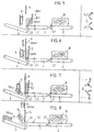
- FIG. 1 to 10 each show a device according to the invention in different stages of its operation. 1, 5 and 7, the support member arranged in the conveying direction of the bale after the separating member is also shown in a top view.
- a device has a belt conveyor 1, a feed belt 2 and a removal belt 3. At the end of the belt conveyor 1 there is a separating member 4 which can be moved back and forth in an at least approximately vertical plane. Above the belt conveyor 1 there is a flap-like support 5. In the exemplary embodiment, a support member 6 arranged in the conveying direction of the bale B after the separating member 4 is designed in the manner of a double-leaf gate.
- control elements in particular light barriers L1, L2 and L3, are arranged one behind the other in the conveying direction of the bale B.
- a bale B lying on the feed belt 2 moves in rapid traverse in the direction of the belt conveyor 1.
- the support 5 is pivoted up and is in its rearmost position.
- the support member 6 is in its inactive position, ie its wings are open.
- the separator 4 is in its upper position.
- this bale B can be conveyed without hindrance and at high speed onto the removal belt 3 and from there into the conditioning system. Its weight could be determined by a weighing device (not shown) assigned to the feed belt 2.
- the light barrier L3 stops the rapid traverse of the belt conveyor 1 and switches over to a slow movement (Fig. 2).
- the path is calculated which is required up to the downward movement of the separating member 4 in order to separate a disk S of the desired thickness.
- the separation of the first slice S is shown in FIG. 3, the detached slice S falling onto the removal belt 3 and being fed from it to the conditioning system.
- the position of the bale B shown in FIG. 4 is reached, in which the latter releases the light barrier L2 and thus causes the support 5 to pivot in.
- the support 5 lies against the rear of the bale B and is moved by it at the same speed, e.g. by coupling with the belt conveyor 1.
- the support member 6 is pivoted in by an appropriate control (FIG. 5), so that support is provided from both sides during the last cut (FIG. 6). .
- the support member 6 is brought back into its inactive position according to FIG. 7, so that the penultimate disk S can fall onto the removal belt 3.
- the last disc SL tilts onto the removal belt 3 (FIG. 8).
- the light barrier L3 is thus released and controls the swiveling up and retraction of the support 5 in accordance with FIGS. 9 and 10. According to the position 5, the next bale B stopped by the light barrier L1 is now conveyed again in rapid traverse to the light barrier L3 and the work cycle begins again.
- the belt conveyor can work step by step during the cutting cycle or it is continuously operated slowly, the bale B slipping on the belt conveyor 1 during the actual cutting process. It is also possible to provide the removal belt 3 with a weighing device.
- the design of the support 5 and the support members 6 can be varied in many ways, as can the design of the control members. Instead of a belt conveyor 1, a roller conveyor, link belt conveyor or another continuous conveyor could also be used.
Landscapes
- Preliminary Treatment Of Fibers (AREA)
- Specific Conveyance Elements (AREA)
Applications Claiming Priority (2)
| Application Number | Priority Date | Filing Date | Title |
|---|---|---|---|
| AT88191A AT396419B (de) | 1991-04-26 | 1991-04-26 | Vorrichtung zum transport und zur abtrennung von scheiben von tabakballen |
| AT881/91 | 1991-04-26 |
Publications (2)
| Publication Number | Publication Date |
|---|---|
| EP0511196A1 true EP0511196A1 (fr) | 1992-10-28 |
| EP0511196B1 EP0511196B1 (fr) | 1994-07-13 |
Family
ID=3501981
Family Applications (1)
| Application Number | Title | Priority Date | Filing Date |
|---|---|---|---|
| EP19920890091 Expired - Lifetime EP0511196B1 (fr) | 1991-04-26 | 1992-04-14 | Dispositif pour le transport et la séparation de tranches des balles de tabac |
Country Status (3)
| Country | Link |
|---|---|
| EP (1) | EP0511196B1 (fr) |
| AT (1) | AT396419B (fr) |
| DE (1) | DE59200275D1 (fr) |
Cited By (7)
| Publication number | Priority date | Publication date | Assignee | Title |
|---|---|---|---|---|
| EP0582139A1 (fr) * | 1992-08-03 | 1994-02-09 | COMAS S.p.A. | Machine à découper en tranches, notamment pour des balles de tabac |
| EP0641523A1 (fr) * | 1993-09-02 | 1995-03-08 | British-American Tobacco Company Limited | Dispositif de coupe pour des balles de tabac |
| US6334447B1 (en) | 1997-09-30 | 2002-01-01 | Universal Leaf Tobacco Co., Inc. | Tobacco bale slicing apparatus and method |
| EP1502511A3 (fr) * | 2003-07-28 | 2005-04-13 | Hauni Maschinenbau AG | Delamination de balles de tabac |
| CN106628894A (zh) * | 2015-11-03 | 2017-05-10 | 红塔烟草(集团)有限责任公司 | 离线烟丝输送装置、离线烟丝自动输送控制系统及方法 |
| CN110367580A (zh) * | 2019-05-14 | 2019-10-25 | 山东中烟工业有限责任公司 | 新型烟块均匀供料装置 |
| CN113068858A (zh) * | 2021-03-02 | 2021-07-06 | 邓旋涛 | 一种用于新鲜烟草叶切丝设备 |
Families Citing this family (1)
| Publication number | Priority date | Publication date | Assignee | Title |
|---|---|---|---|---|
| DE102013107248B4 (de) * | 2013-07-09 | 2016-05-25 | Hauni Maschinenbau Ag | Vorrichtung, ausgebildet und eingerichtet zum automatischen Trennen von Scheiben von einem aus Material der Tabak verarbeitenden Industrie bestehenden Ballen |
Citations (2)
| Publication number | Priority date | Publication date | Assignee | Title |
|---|---|---|---|---|
| DE1139419B (de) * | 1960-09-20 | 1962-11-08 | Reemtsma H F & Ph | Vorrichtung zum Abtrennen von Scheiben von einem Tabakballen |
| WO1987002868A1 (fr) * | 1985-11-13 | 1987-05-21 | Gbe International Plc | Machine a trancher des blocs de tabac |
-
1991
- 1991-04-26 AT AT88191A patent/AT396419B/de not_active IP Right Cessation
-
1992
- 1992-04-14 EP EP19920890091 patent/EP0511196B1/fr not_active Expired - Lifetime
- 1992-04-14 DE DE59200275T patent/DE59200275D1/de not_active Expired - Fee Related
Patent Citations (2)
| Publication number | Priority date | Publication date | Assignee | Title |
|---|---|---|---|---|
| DE1139419B (de) * | 1960-09-20 | 1962-11-08 | Reemtsma H F & Ph | Vorrichtung zum Abtrennen von Scheiben von einem Tabakballen |
| WO1987002868A1 (fr) * | 1985-11-13 | 1987-05-21 | Gbe International Plc | Machine a trancher des blocs de tabac |
Non-Patent Citations (1)
| Title |
|---|
| RESEARCH DISCLOSURE. Nr. 321, Januar 1991, EMSWORTH GB Seite 15; ANONYMOUSLY 32124: 'slicing apparatus' * |
Cited By (12)
| Publication number | Priority date | Publication date | Assignee | Title |
|---|---|---|---|---|
| EP0582139A1 (fr) * | 1992-08-03 | 1994-02-09 | COMAS S.p.A. | Machine à découper en tranches, notamment pour des balles de tabac |
| AU656684B2 (en) * | 1992-08-03 | 1995-02-09 | Comas S.P.A. | A slicing machine, particularly for bales of tobacco |
| US5435218A (en) * | 1992-08-03 | 1995-07-25 | Comas S.P.A. | Slicing machine |
| EP0641523A1 (fr) * | 1993-09-02 | 1995-03-08 | British-American Tobacco Company Limited | Dispositif de coupe pour des balles de tabac |
| US6334447B1 (en) | 1997-09-30 | 2002-01-01 | Universal Leaf Tobacco Co., Inc. | Tobacco bale slicing apparatus and method |
| US6446633B2 (en) | 1997-09-30 | 2002-09-10 | Universal Leaf Tobacco Co., Inc. | Tobacco bale slicing apparatus and method |
| EP1502511A3 (fr) * | 2003-07-28 | 2005-04-13 | Hauni Maschinenbau AG | Delamination de balles de tabac |
| CN106628894A (zh) * | 2015-11-03 | 2017-05-10 | 红塔烟草(集团)有限责任公司 | 离线烟丝输送装置、离线烟丝自动输送控制系统及方法 |
| CN110367580A (zh) * | 2019-05-14 | 2019-10-25 | 山东中烟工业有限责任公司 | 新型烟块均匀供料装置 |
| CN110367580B (zh) * | 2019-05-14 | 2022-04-29 | 山东中烟工业有限责任公司 | 烟块均匀供料装置 |
| CN113068858A (zh) * | 2021-03-02 | 2021-07-06 | 邓旋涛 | 一种用于新鲜烟草叶切丝设备 |
| CN113068858B (zh) * | 2021-03-02 | 2023-10-13 | 彭海燕 | 一种用于新鲜烟草叶切丝设备 |
Also Published As
| Publication number | Publication date |
|---|---|
| DE59200275D1 (de) | 1994-08-18 |
| AT396419B (de) | 1993-09-27 |
| ATA88191A (de) | 1993-01-15 |
| EP0511196B1 (fr) | 1994-07-13 |
Similar Documents
| Publication | Publication Date | Title |
|---|---|---|
| DE60204432T2 (de) | Verfahren und vorrichtung zum schneiden einer anzahl von artikeln, insbesondere tomaten in eine vielzahl von dünnen uniformen scheiben in einer einzelnen handlung | |
| DE69320736T2 (de) | Maschine zum Abtrennen von Scheiben, insbesondere von Tabakballen | |
| DE1524522C3 (de) | Lochkartenmaschine | |
| EP0868982B1 (fr) | Dispositif d'empilage de produits débités en tranches | |
| DE1285394B (de) | Vorrichtung zum Unterteilen eines Stranges von aneinandergereihten flachen Gegenstaenden in Gruppen | |
| EP0511196B1 (fr) | Dispositif pour le transport et la séparation de tranches des balles de tabac | |
| EP0699395A2 (fr) | Dispositif pour la coupe en tranches de ballots | |
| DE2224375A1 (fr) | ||
| DE1660126A1 (de) | Verfahren und Vorrichtung zum Falten und Stapeln flexiblen flaechigen Guts | |
| DE9301072U1 (de) | Sammelvorrichtung für Blätter zur Bildung von Blattstapeln | |
| DE2806533C3 (de) | Vorrichtung zum Perforieren von Zigaretten | |
| DE2236181A1 (de) | Einrichtung zur schrittweisen einspeisung empfindlicher koerper in eine mit einer kontinuierlichen bewegung beaufschlagte aufnahmestrecke | |
| DE2915716A1 (de) | Verfahren zur beseitigung des vorderund hinterabschnitts von walzdraht und vorrichtung zur durchfuehrung des verfahrens | |
| DE19851149A1 (de) | Aufschneidemaschine für Lebensmittelriegel | |
| DE1139419B (de) | Vorrichtung zum Abtrennen von Scheiben von einem Tabakballen | |
| EP0657259A1 (fr) | Dispositif de coupe pour boudin d'argile | |
| DE1652759A1 (de) | Stapelvorrichtung | |
| EP2417860A1 (fr) | Dispositif et procédé de séparation de parties de balles d'un produit comprimé | |
| EP0705159B1 (fr) | Dispositif destine a decouper des tranches de balles de tabac ou de matieres comprimeees similaires | |
| DE2724322A1 (de) | Vorrichtung zum zuschneiden und transportieren eines silageblockes | |
| DE2520428A1 (de) | Als endlos-kettenstabband ausgebildete vorschubeinrichtung fuer verpackungsgueter | |
| DE1815651A1 (de) | Vorrichtung zum Stapeln von Blechen auf einem Hubtisch | |
| DE1158695B (de) | Furnier-Ablege-Vorrichtung | |
| DE1918812A1 (de) | Einrichtung zum Vorsortieren von Kartoffeln und aehnlichen Produkten | |
| DE700310C (de) | chinen |
Legal Events
| Date | Code | Title | Description |
|---|---|---|---|
| PUAI | Public reference made under article 153(3) epc to a published international application that has entered the european phase |
Free format text: ORIGINAL CODE: 0009012 |
|
| AK | Designated contracting states |
Kind code of ref document: A1 Designated state(s): DE GB IT |
|
| 17P | Request for examination filed |
Effective date: 19920904 |
|
| RIN1 | Information on inventor provided before grant (corrected) |
Inventor name: SCHMIDT, GUENTHER |
|
| 17Q | First examination report despatched |
Effective date: 19931213 |
|
| GRAA | (expected) grant |
Free format text: ORIGINAL CODE: 0009210 |
|
| ITF | It: translation for a ep patent filed | ||
| AK | Designated contracting states |
Kind code of ref document: B1 Designated state(s): DE GB IT |
|
| GBT | Gb: translation of ep patent filed (gb section 77(6)(a)/1977) |
Effective date: 19940714 |
|
| REF | Corresponds to: |
Ref document number: 59200275 Country of ref document: DE Date of ref document: 19940818 |
|
| PLBE | No opposition filed within time limit |
Free format text: ORIGINAL CODE: 0009261 |
|
| 26N | No opposition filed | ||
| PGFP | Annual fee paid to national office [announced via postgrant information from national office to epo] |
Ref country code: DE Payment date: 20000315 Year of fee payment: 9 |
|
| PGFP | Annual fee paid to national office [announced via postgrant information from national office to epo] |
Ref country code: GB Payment date: 20000403 Year of fee payment: 9 |
|
| PG25 | Lapsed in a contracting state [announced via postgrant information from national office to epo] |
Ref country code: GB Free format text: LAPSE BECAUSE OF NON-PAYMENT OF DUE FEES Effective date: 20010414 |
|
| GBPC | Gb: european patent ceased through non-payment of renewal fee |
Effective date: 20010414 |
|
| PG25 | Lapsed in a contracting state [announced via postgrant information from national office to epo] |
Ref country code: DE Free format text: LAPSE BECAUSE OF NON-PAYMENT OF DUE FEES Effective date: 20020201 |
|
| PG25 | Lapsed in a contracting state [announced via postgrant information from national office to epo] |
Ref country code: IT Free format text: LAPSE BECAUSE OF NON-PAYMENT OF DUE FEES;WARNING: LAPSES OF ITALIAN PATENTS WITH EFFECTIVE DATE BEFORE 2007 MAY HAVE OCCURRED AT ANY TIME BEFORE 2007. THE CORRECT EFFECTIVE DATE MAY BE DIFFERENT FROM THE ONE RECORDED. Effective date: 20050414 |