EP0511580A2 - Métier à tricoter à chaîne avec une barre à passettes comportant des guides-fils individuellement mobiles - Google Patents
Métier à tricoter à chaîne avec une barre à passettes comportant des guides-fils individuellement mobiles Download PDFInfo
- Publication number
- EP0511580A2 EP0511580A2 EP92106861A EP92106861A EP0511580A2 EP 0511580 A2 EP0511580 A2 EP 0511580A2 EP 92106861 A EP92106861 A EP 92106861A EP 92106861 A EP92106861 A EP 92106861A EP 0511580 A2 EP0511580 A2 EP 0511580A2
- Authority
- EP
- European Patent Office
- Prior art keywords
- thread guides
- warp knitting
- knitting machine
- control cables
- tension control
- Prior art date
- Legal status (The legal status is an assumption and is not a legal conclusion. Google has not performed a legal analysis and makes no representation as to the accuracy of the status listed.)
- Withdrawn
Links
Images
Classifications
-
- D—TEXTILES; PAPER
- D04—BRAIDING; LACE-MAKING; KNITTING; TRIMMINGS; NON-WOVEN FABRICS
- D04B—KNITTING
- D04B27/00—Details of, or auxiliary devices incorporated in, warp knitting machines, restricted to machines of this kind
- D04B27/10—Devices for supplying, feeding, or guiding threads to needles
- D04B27/24—Thread guide bar assemblies
- D04B27/32—Thread guide bar assemblies with independently-movable thread guides controlled by Jacquard mechanisms
-
- D—TEXTILES; PAPER
- D04—BRAIDING; LACE-MAKING; KNITTING; TRIMMINGS; NON-WOVEN FABRICS
- D04B—KNITTING
- D04B27/00—Details of, or auxiliary devices incorporated in, warp knitting machines, restricted to machines of this kind
- D04B27/10—Devices for supplying, feeding, or guiding threads to needles
- D04B27/24—Thread guide bar assemblies
- D04B27/26—Shogging devices therefor
-
- Y—GENERAL TAGGING OF NEW TECHNOLOGICAL DEVELOPMENTS; GENERAL TAGGING OF CROSS-SECTIONAL TECHNOLOGIES SPANNING OVER SEVERAL SECTIONS OF THE IPC; TECHNICAL SUBJECTS COVERED BY FORMER USPC CROSS-REFERENCE ART COLLECTIONS [XRACs] AND DIGESTS
- Y02—TECHNOLOGIES OR APPLICATIONS FOR MITIGATION OR ADAPTATION AGAINST CLIMATE CHANGE
- Y02P—CLIMATE CHANGE MITIGATION TECHNOLOGIES IN THE PRODUCTION OR PROCESSING OF GOODS
- Y02P70/00—Climate change mitigation technologies in the production process for final industrial or consumer products
- Y02P70/50—Manufacturing or production processes characterised by the final manufactured product
- Y02P70/62—Manufacturing or production processes characterised by the final manufactured product related technologies for production or treatment of textile or flexible materials or products thereof, including footwear
Definitions
- the invention relates to a warp knitting machine with at least one laying bar, on which individual thread guides can be individually moved back and forth, which are combined into one or more groups and are moved in groups by a common pattern drive.
- Such a warp knitting machine is known from DE-PS 27 06 974.
- Such a warp knitting machine enables warp knitting to be patterned, which is restricted compared to the unlimited patterning possibility by means of a jacquard control, since not all thread guides can be moved individually, but the movement of the thread guides in a group, which is carried out in groups by a common pattern drive, is sufficient for a large number of desired patterns. Due to the grouping of the thread guides with group-wise common pattern drive, there is a significant increase in the working speed of the warp knitting machine in question compared to that with a jacquard control, thus saving considerable effort.
- a group movement of individual thread guides is further described in DE-OS 38 00 381.
- the pattern drives are attached together with the individually back and forth thread guides on the respective laying bars, i. that is, the mass of each laying bar is increased by the pattern drive, which counteracts a desirable rapid movement of the laying bars in the sense of a high performance of the warp knitting machine with a corresponding inertia resistance.
- the invention has for its object to further increase the working speed of the warp knitting machine explained at the beginning with a small space requirement and rapid adaptation to pattern changes.
- the pattern drives are designed as servomotors which are electrically controlled by a program control and are mounted independently of the laying bar and which are connected to the thread guides via tension control cables which are kept under tension.
- the tension control cables connected to the thread guides Due to the use of the tension control cables connected to the thread guides, there is on the one hand a low mass inertia for this part of the drive of the thread guides, and on the other hand a small space requirement, the tension control cables due to the inherent flexibility of any deflections and thus an adaptation of the position of the electric servomotors to the design Allow conditions of a warp knitting machine. Due to the low mass inertia, the working speed of the warp knitting machine in question can be increased accordingly.
- the use of the electric control motors pulling the pull control cables allows the warp knitting machine in question to be quickly adapted to changing patterns, since such control motors are able to process signals supplied by a control circuit at high speed in a known manner, the control can be easily and quickly switched to other patterns.
- either only one or more laying bars can be equipped with individually movable thread guides combined in groups, which results in a corresponding breadth of variation with regard to the pattern possibility.
- the laying bars designed according to the invention are designed to be particularly space-saving with respect to the drive of the movable thread guides and adaptable with regard to the overall arrangement, there is the possibility, if necessary, of replacing a laying bar according to the invention by a normal, fully occupied laying bar and vice versa, which simplifies the operation of the warp knitting machine in question Can be adapted to a wide variety of needs.
- the tension control cables can be kept under tension by attaching them to tension springs with their side facing away from the servomotors.
- the servomotors do not have to overcome the force of a tension spring, so that they can be moved correspondingly faster. So you can get by with actuators of lower power.
- the train control cables are expediently given such a guide that the train control cables are deflected towards the pattern drive approximately at right angles to the direction of displacement of the guide bar, the deflected region of the train control cables runs next to the end face of the axis of the laying bar pivot shaft and essentially intersects the alignment line of this axis.
- the special movements of the bar can then have practically no effect on the control cables.
- the laying bars are removed from their normal storage in the usual way and, at a distance from the other bars, are hung in order to make the removed laying bar easily accessible for pulling the threads.
- this can be facilitated in that a deflection for the train control cables is arranged upstream of the servomotors and the bearing of the guide can be triggered to release the train control cables.
- the train control cables are released, which can easily sag, thereby giving the laying bar concerned the freedom to hang it in an accessible location.
- the detachable mounting is advantageously provided with a tensioning device for the train control cable in question, so that the release of the train control cables as well as their necessary tension can be brought about with the same component.
- the drive is expediently designed in such a way that the connection between tension control cable and thread guide contains a spring bar and stops to limit the back and forth movement of the thread guides are attached to the bar.
- the back and forth movement of the thread guides is then exactly limited by the stops, without the servomotors being required to have a corresponding positioning accuracy.
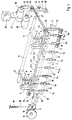
- the laying bar 1 of a warp knitting machine shown in FIG. 1 consists here of the carrier 2 for the thread guides 3 which can be moved back and forth in the direction of offset and which are designed as perforated needles and the carrier 4 for thread guides 5 which are attached to this rod and are also made of perforated needles 5.
- the two carriers 3 and 4 are firmly connected to one another, so that the thread guides 3 and 5 vibrate together through the needle lanes of the knitting needles of the warp knitting machine concerned during the swinging movements of the laying bar 1.
- the knitting needles were not shown in the design of FIG. 1, since the cooperation between knitting needles and thread guides of a warp knitting machine is a function that has been known since warp knitting machines existed. For this reason, other organs of a warp knitting machine that are not of interest in this connection have been omitted.
- the bar 1 hangs on the two support arms 6 and 7, from which the guide bolts 8 and 9 protrude, which are held in axial guide bearings 10 and 11. Because of this mounting, the bar 1 can be moved back and forth in its longitudinal direction, whereupon it will be discussed in more detail below.
- the axial guide bearings 10 and 11 are fastened to the swivel arms 12 and 13, which are rotatably mounted on the bar swivel shaft 14.
- the laying bar pivot shaft 14 is moved in a known manner back and forth by the drive of the warp knitting machine, whereby the thread guides 3 and 5 have the above-mentioned Swiveling movement to swing through the needle lanes is given. This is also a known function.
- the laying bar 1 is also in the so-called offset direction, i.e. H. in its longitudinal direction, a back and forth movement, which is pressed onto the position bar 1 by means of the cam disc 15.
- the cam disc 15 rotates about its axis 16
- the cam disc pushes the roller 17 back and forth, the roller 17 transmitting its movement in the offset direction to the plunger 18 and thus to the laying bar 1.
- This back and forth movement in the offset direction is indicated by the double arrow indicated on the pestle 18. So that the roller 17 is always in contact with the cam disc 15, the bar 1 is pulled via the spring 19, the pull rope 20 and the hook 21 in the direction of the cam disc 15.
- the thread guides 3 and 5 carry out the process of swinging through the needle lanes in different needle lanes, which results in the desired appearance of the knitted fabric.
- the thread guides 5 carry out the layings which essentially shape the goods to be manufactured.
- the thread guides 5 are therefore arranged over the entire length of the laying bar 1.
- FIG. 1 shows, 5 gaps are left in the row of thread guides which are filled by thread guides 3. If the thread guides 5 and 3 are constantly held in their position shown, the result is a uniform stitch pattern of the goods to be produced over their entire width.
- the thread guides 5 form a group within which all thread guides 5 can be moved back and forth in the offset direction. During this back and forth movement, the thread guides 5 go back and forth from a normal position into a pattern position, as will be explained in more detail in connection with FIG. 3. In the normal position, as shown in FIG. 1, the threads laid by the thread guides 3 are placed evenly between the threads laid by the thread guides 5, so that the above-mentioned uniform stitch pattern results.
- the thread guides 3 are moved from their normal position into the pattern position, specifically in the direction of offset of the laying bar 1. This movement is given to the thread guides 3a and 3b by means of the tension control cables 22 and 23 that are guided as an endless rope.
- the parts 22h and 23h form the feed and the parts 22r and 23r the return of the train control cable in question.
- the tension control cables 22 and 23 are guided at the end of the bar 1 on the cam disc side by means of outer rollers 24. They are then redirected again by the deflection rollers 26, namely the tension control cable 22 to the electric servomotor 27 and the tension control cable 23 to the electric servomotor 28.
- These electric servomotors 27 and 28 are controlled by a program control 29 held in synchronism with the other movements of the warp knitting machine. in such a way that the servomotors 27 and 28 turn their drive wheels 30 and 31 back and forth, as a result of which the control cables 22 and 23 are pressed in the direction of their displacement back and forth in the offset direction in the area of their feed 22h and 23h.
- This back and forth movement of the guides 22h and 23h is now transmitted to the levers 32 and 33 attached to these guides, which give the thread guide holders 34 and 35 attached to them a corresponding pivoting movement.
- the thread guide holder 34 and 35 are pivoted for this purpose on axes 36 on the carrier.
- the thread guides 3a and 3b thus execute a corresponding back and forth movement in accordance with the back and forth movement of the guides 22h and 23h, in which the thread guides 3a and 3b move from their normal position into the pattern position and back.
- the two separately controllable servomotors 27 and 28 enable the two groups of thread guides 3a and 3b to be moved back and forth differently move, with which a corresponding variation in the pattern can be achieved. If further variations with regard to the patterning are desired, then correspondingly more servomotors and tension control cables and with thread guides controlled by them are to be provided.
- the carrier 4 shown in FIG. 1 with its thread guides 5 attached to it can also be mounted independently of the carrier 3 separately in their own support arms 6 and 7 and guide bolts 8 and 9 with the associated axial bearings 10 and 11. In this case, it can also be controlled in the offset direction by a separate cam disk 15. For reasons of clarity, this separate storage is not shown in FIG. 1.
- the actuating mechanism for the two groups of thread guides 3a and 3b shown in FIG. 1 essentially consists of the relevant control cable 22 and 23 and the two servomotors 27 and 28, the servomotors 27 and 28 not requiring much energy for the back and forth movement of the Tension control cables 22 and 23 as well as the thread guides 3a and 3b controlled by these are required, since these organs are relatively light components. This has a correspondingly favorable influence on the speed of movement of the laying bar 1, which can be correspondingly high.
- the deflection rollers 26 are mounted at the end of the link 39 which is rotatably mounted on the axle 38. With the pivoting of the handlebar 39, the tension in the tension control cables 22 and 23 can be correspondingly reduced or increased.
- the desired tension can be adjusted in that the fixing screw 40, under which the elongated hole 21 is arranged in the handlebar 39, is tightened against the handlebar 39.
- the tension of the two tension control cables 22 and 23 can be adjusted.
- the tension control cables 22 and 23 are released, for which purpose the handlebar 39 is pivoted in the direction of the deflection rollers 25 after loosening the fixing screw 40, whereby the tension control cables 22 and 23 are released and the laying bar 1 then can be removed from their storage in a known manner.
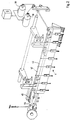
- the laying bar 1 shown in FIG. 2 corresponds completely to that according to FIG. 1 in terms of its storage and control, so that reference can be made to the explanation of FIG. 1 in this regard.
- only another guidance of the two tension control cables 42 and 43 is provided. These are not endless traction control cables as in the arrangement according to FIG. 1, but traction control cables which are tensioned on one side by the tension springs 44 and 45 and are wound up and unwound by the drive wheels 30 and 31 on their other side.
- the tension control cables 42 and 43 like the feeders 22h and 23h according to FIG. 1, perform a back and forth movement in the offset direction, as a result of which the thread guides 3a and 3b are moved back and forth accordingly, as in the arrangement according to FIG. Otherwise, the arrangement according to FIG. 2 corresponds completely to FIG. 1.
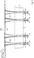
- FIG 3 the carrier 2 of the bar 1 is shown alone, with two groups of back and forth thread guides 46 and 47.
- the thread guides 46 and 47 are mounted on the carrier 2 as in the arrangements of Figure 1 and Figure 2.
- the stops 51 and 52 are provided for the back and forth movement of the thread guides 46 and 47, the thread guides 46 and 47 taking the normal position in the position shown in full lines, while the pattern position is represented by the dashed lines (reference symbol 53).
- the thread guides 46 and 47 are each given a defined end position during the back and forth movement of the tension control cable 50, so that there are clear relationships with respect to the needle paths through which the thread guides 46 and 47 are pivoted.
- the tension control cable 50 can easily have a certain overstroke slightly without close tolerance, which is then absorbed by a corresponding bending of the thread rods 48 and 49.
- the stiffness of the spring bars 48 and 49 must be chosen so that the forces exerted by the threads on the thread guides 46 and 47 are fully absorbed by the spring bars 48 and 49, ie the thread guides 46 and 47 in their through the stops 51 and 52 defined positions are held under the tension of the spring rods 48 and 49 at the stops.
- FIG. 3 also shows a special feature for the patterning, namely the connection of the spring bars 48 to the feed 50h and the connection of the spring bars 49 to the return 50r.
- a servomotor which is responsible for the movement of the tension control cable 50 is then required.
Landscapes
- Engineering & Computer Science (AREA)
- Textile Engineering (AREA)
- Knitting Machines (AREA)
Applications Claiming Priority (2)
| Application Number | Priority Date | Filing Date | Title |
|---|---|---|---|
| DE4114012A DE4114012C3 (de) | 1991-04-29 | 1991-04-29 | Kettenwirkmaschine mit auf einer Legebarre angebrachten individuell bewegbaren Fadenführern |
| DE4114012 | 1991-04-29 |
Publications (2)
| Publication Number | Publication Date |
|---|---|
| EP0511580A2 true EP0511580A2 (fr) | 1992-11-04 |
| EP0511580A3 EP0511580A3 (en) | 1993-03-24 |
Family
ID=6430621
Family Applications (1)
| Application Number | Title | Priority Date | Filing Date |
|---|---|---|---|
| EP19920106861 Withdrawn EP0511580A3 (en) | 1991-04-29 | 1992-04-22 | Warpknittingmachine with a weft inlay bar provided with individually movable thread guides |
Country Status (6)
| Country | Link |
|---|---|
| US (1) | US5241842A (fr) |
| EP (1) | EP0511580A3 (fr) |
| JP (1) | JPH0665847A (fr) |
| KR (1) | KR940011011B1 (fr) |
| CN (1) | CN1028041C (fr) |
| DE (1) | DE4114012C3 (fr) |
Cited By (6)
| Publication number | Priority date | Publication date | Assignee | Title |
|---|---|---|---|---|
| US5768916A (en) * | 1995-10-11 | 1998-06-23 | Textilma Ag | Warp knitting machine |
| EP0971060A1 (fr) * | 1998-07-08 | 2000-01-12 | Aplix | Procédé de formation par tricotage de boucles sur une feuille, tissu à boucles réalisé selon ce procédé, et son utilisation |
| WO2008043219A1 (fr) * | 2006-10-10 | 2008-04-17 | Yu-Hsin Wu | Mécanisme de levage automatique de guide-fil |
| CN104652034A (zh) * | 2015-02-06 | 2015-05-27 | 常州市宏发纵横新材料科技股份有限公司 | 经编机铺纬装置和铺纬方法 |
| EP3511460A3 (fr) * | 2019-04-30 | 2019-09-18 | KARL MAYER Textilmaschinenfabrik GmbH | Métier à tricoter à chaîne et procédé d'aide à la commande d'un métier à tricoter à chaîne |
| CN117107413A (zh) * | 2023-10-25 | 2023-11-24 | 江苏维凯科技股份有限公司 | 一种ptfe遮阳帘用玻纤基布提花织造装置 |
Families Citing this family (24)
| Publication number | Priority date | Publication date | Assignee | Title |
|---|---|---|---|---|
| DE4303967C2 (de) * | 1993-02-10 | 1995-03-30 | Liba Maschf | Kettenwirkmaschine mit auf einer Legebarre angebrachten individuell bewegbaren Fadenführern |
| DE4335278C1 (de) * | 1993-10-15 | 1995-01-05 | Liba Maschf | Kettenwirkmaschine mit auf einer Legebarre schwenkbar gelagerten Fadenführern |
| JPH07197358A (ja) * | 1993-12-28 | 1995-08-01 | Etsuzou Sasaki | ジャカードガイド及びジャカードガイドユニット |
| US5675993A (en) * | 1994-01-14 | 1997-10-14 | Nippon Mayer Co. Ltd. | Patterning method and device in warp knitting machine |
| DE4414876C2 (de) * | 1994-04-28 | 1996-05-30 | Mayer Textilmaschf | Verfahren zum Herstellen einer Kettenwirkware, Kettenwirkmaschine zur Durchführung dieses Verfahrens und Kettenwirkware |
| DE4444822C2 (de) * | 1994-12-15 | 1998-01-08 | Liba Maschf | Kettenwirkmaschine mit auf einer Legebarre angebrachten, individuell bewegbaren Fadenführern |
| CN1057358C (zh) * | 1995-01-13 | 2000-10-11 | 日本迈耶株式会社 | 经编机上的提花装置 |
| DE19605117C2 (de) * | 1996-02-12 | 2001-02-01 | Liba Maschf | Kettenwirkmaschine mit Jacquard-Steuerung |
| US5899095A (en) * | 1998-01-21 | 1999-05-04 | Liberty Fabrics | Jacquard fabric and method of manufacturing |
| DE19938871C1 (de) * | 1999-08-17 | 2001-05-10 | Mayer Textilmaschf | Kettenwirkmaschine |
| DE10035160B4 (de) * | 2000-07-19 | 2004-06-03 | Karl Mayer Textilmaschinenfabrik Gmbh | Kettenwirkmaschine mit mindestens einer Barre |
| DE10137601B4 (de) * | 2001-08-01 | 2006-09-07 | Karl Mayer Textilmaschinenfabrik Gmbh | Kettenwirkmaschine mit mindestens einer Musterlegebarre |
| US8246882B2 (en) * | 2003-05-02 | 2012-08-21 | The Boeing Company | Methods and preforms for forming composite members with interlayers formed of nonwoven, continuous materials |
| US20080289743A1 (en) | 2003-05-02 | 2008-11-27 | Tsotsis Thomas K | Highly porous interlayers to toughen liquid-molded fabric-based composites |
| US20050257887A1 (en) * | 2004-05-24 | 2005-11-24 | Tsotsis Thomas K | Method and apparatus for melt-bonded materials for tackification of dry fabric preforms |
| DE10332235B3 (de) * | 2003-07-16 | 2005-06-16 | Karl Mayer Textilmaschinenfabrik Gmbh | Kettenwirkmaschine |
| DE102004031268A1 (de) * | 2004-06-29 | 2006-02-02 | Karl Mayer Textilmaschinenfabrik Gmbh | Legebarrenantrieb in einer Wirkmaschine |
| US20060048881A1 (en) * | 2004-09-08 | 2006-03-09 | Evans Richard B | Laser-assisted placement of veiled composite material |
| KR100767752B1 (ko) * | 2006-07-07 | 2007-10-19 | 박승헌 | 라셀 경편기의 가이드바 가동 장치 |
| FR2951664B1 (fr) | 2009-10-23 | 2011-12-16 | Hexcel Reinforcements | Empilement multiaxial solidarise par des soudures ponctuelles realisees grace a des voiles thermoplastiques intercalaires |
| EP2615197A1 (fr) * | 2012-01-10 | 2013-07-17 | Karl Mayer Textilmaschinenfabrik GmbH | Agencement de barres de stockage d'un métier à tricoter à chaîne |
| EP2623653A1 (fr) * | 2012-02-04 | 2013-08-07 | Karl Mayer Textilmaschinenfabrik GmbH | Agencement de barres de stockage d'un métier à tricoter à chaîne |
| PL2826902T3 (pl) * | 2013-07-19 | 2019-05-31 | Kufner Holding Gmbh | Sposób wytwarzania tekstylnego, powierzchniowego elementu grzejnego oraz osnowarka lub osnowarka raszlowa z magazynującym systemem podania wątków |
| CN108217332A (zh) * | 2018-01-25 | 2018-06-29 | 常州市第八纺织机械有限公司 | 一种主动送线装置及其控制方法 |
Family Cites Families (17)
| Publication number | Priority date | Publication date | Assignee | Title |
|---|---|---|---|---|
| DE277378C (fr) * | ||||
| US1972609A (en) * | 1931-10-03 | 1934-09-04 | Raalte Company Van | Warp knitting machine |
| US3074259A (en) * | 1959-08-19 | 1963-01-22 | Bassist Rudolph George | Knitting machine provided with independently adjustable thread-guide element |
| DE2035750A1 (en) * | 1970-07-18 | 1972-01-27 | Liebrandt, Karl, 8674 Naila | Knitting machine drop plate motion - at angle to the latch needle axis to increase operating speeds |
| DE2060101C3 (de) * | 1970-12-07 | 1973-09-13 | Karl Mayer, Textil-Maschinenfabrik Gmbh, 6053 Obertshausen | Kettenwirkmaschine mit schwin gender Nadelbarre |
| GB1445374A (en) * | 1973-02-26 | 1976-08-11 | Sigma Instruments Inc | Selective positioning system particularly for onctrolling guide bars of knitting machines |
| DE2459872A1 (de) * | 1974-01-23 | 1975-07-24 | Heidenau Netz & Seil Veb | Sack und verfahren zur herstellung desselben |
| DE2706974C3 (de) * | 1977-02-18 | 1979-11-08 | Karl Mayer Textil-Maschinen-Fabrik Gmbh, 6053 Obertshausen | Kettenwirkmaschine mit mehreren teilschuOlegenden SchuBfadenführern |
| DE3023952A1 (de) * | 1980-06-26 | 1982-01-14 | Karl Mayer Textil-Maschinen-Fabrik Gmbh, 6053 Obertshausen | Kettenwirkmaschine |
| EP0059168B1 (fr) * | 1981-02-19 | 1985-10-02 | Ciba-Geigy Ag | Elastomères organiques et huiles lubrifiantes minérales et synthétiques contenant des esters phénolmercaptocarboxyliques comme stabilisants |
| JPS588793U (ja) * | 1981-07-10 | 1983-01-20 | 株式会社日立製作所 | 送風機の振動監視装置 |
| DE3130555A1 (de) * | 1981-08-01 | 1983-02-17 | Karl 6053 Obertshausen Kohl | Kettenwirkmaschine mit jacquardeinrichtung |
| IT1153279B (it) * | 1982-10-21 | 1987-01-14 | Comez Spa | Macchina tessile perfezionata per la formazione di tessuti di vari colori e disegni |
| DE3321733C2 (de) * | 1983-06-16 | 1985-06-20 | Karl Mayer Textil-Maschinen-Fabrik Gmbh, 6053 Obertshausen | Kettenwirkmaschine mit Jacquard-Lochnadeln |
| DE3642523A1 (de) * | 1985-03-07 | 1987-09-10 | Textima Veb K | Kettenwirkmaschine, insbesondere haekelgalonmaschine |
| DD256882A1 (de) * | 1986-12-31 | 1988-05-25 | Tech Uni Dresen Direkt Forsch | Steuersystem fuer kettfaeden |
| IT211978Z2 (it) * | 1987-07-21 | 1989-05-25 | Comez Spa | Dispositivo di comando di tubetti guidafilo in telai per galloni ad uncinetto. |
-
1991
- 1991-04-29 DE DE4114012A patent/DE4114012C3/de not_active Expired - Fee Related
-
1992
- 1992-04-22 US US07/871,944 patent/US5241842A/en not_active Expired - Fee Related
- 1992-04-22 EP EP19920106861 patent/EP0511580A3/de not_active Withdrawn
- 1992-04-27 JP JP4107242A patent/JPH0665847A/ja active Pending
- 1992-04-28 KR KR1019920007183A patent/KR940011011B1/ko not_active Expired - Fee Related
- 1992-04-29 CN CN92103158A patent/CN1028041C/zh not_active Expired - Fee Related
Cited By (9)
| Publication number | Priority date | Publication date | Assignee | Title |
|---|---|---|---|---|
| US5768916A (en) * | 1995-10-11 | 1998-06-23 | Textilma Ag | Warp knitting machine |
| CH690183A5 (de) * | 1995-10-11 | 2000-05-31 | Textilma Ag | Kettenwirkmaschine. |
| EP0971060A1 (fr) * | 1998-07-08 | 2000-01-12 | Aplix | Procédé de formation par tricotage de boucles sur une feuille, tissu à boucles réalisé selon ce procédé, et son utilisation |
| FR2780989A1 (fr) * | 1998-07-08 | 2000-01-14 | Aplix Sa | Procede de formation par tricotage de boucles sur une feuille, tissu a boucles realise selon ce procede, et son utilisation |
| WO2008043219A1 (fr) * | 2006-10-10 | 2008-04-17 | Yu-Hsin Wu | Mécanisme de levage automatique de guide-fil |
| CN104652034A (zh) * | 2015-02-06 | 2015-05-27 | 常州市宏发纵横新材料科技股份有限公司 | 经编机铺纬装置和铺纬方法 |
| EP3511460A3 (fr) * | 2019-04-30 | 2019-09-18 | KARL MAYER Textilmaschinenfabrik GmbH | Métier à tricoter à chaîne et procédé d'aide à la commande d'un métier à tricoter à chaîne |
| CN117107413A (zh) * | 2023-10-25 | 2023-11-24 | 江苏维凯科技股份有限公司 | 一种ptfe遮阳帘用玻纤基布提花织造装置 |
| CN117107413B (zh) * | 2023-10-25 | 2024-01-12 | 江苏维凯科技股份有限公司 | 一种ptfe遮阳帘用玻纤基布提花织造装置 |
Also Published As
| Publication number | Publication date |
|---|---|
| DE4114012A1 (de) | 1992-11-05 |
| DE4114012C2 (fr) | 1993-02-18 |
| JPH0665847A (ja) | 1994-03-08 |
| KR940011011B1 (ko) | 1994-11-22 |
| EP0511580A3 (en) | 1993-03-24 |
| KR920019990A (ko) | 1992-11-20 |
| DE4114012C3 (de) | 1996-07-04 |
| CN1028041C (zh) | 1995-03-29 |
| US5241842A (en) | 1993-09-07 |
| CN1066305A (zh) | 1992-11-18 |
Similar Documents
| Publication | Publication Date | Title |
|---|---|---|
| DE4114012C2 (fr) | ||
| DE4303967C2 (de) | Kettenwirkmaschine mit auf einer Legebarre angebrachten individuell bewegbaren Fadenführern | |
| CH617232A5 (fr) | ||
| DE2531734A1 (de) | Fadenfuehrung an maschenbildenden maschinen mit umlaufenden fadenfuehrern | |
| DE3219860C2 (de) | Elektronisch gesteuerte Flachstrickmaschine | |
| DE69513234T2 (de) | Mustervorrichtung für eine kettenwirkmaschine | |
| EP1564320B1 (fr) | Dispositif de formation de la foule pour un métier à tisser | |
| EP0338194A2 (fr) | Procédé pour la fabrication d'articles de tricot-intarsia et métier à tricoter rectiligne pour la mise en oeuvre de ce procédé | |
| DE102004001068B4 (de) | Vorrichtung für eine Webmaschine | |
| EP3741892B1 (fr) | Métier à tisser destiné à la fabrication de produits tissés dotés d'un fils à effet incorporé | |
| DE19781593B4 (de) | Steuervorrichtung für maschenbildende Elemente in einer Kettenwirkmaschine | |
| EP0302209B1 (fr) | Métier à crochets pour galons | |
| DE3823475A1 (de) | Maschinenverknuepfte maschenwaren | |
| DE2933841A1 (de) | Einrichtung fuer eine maschine fuer die herstellung flaechenhafter textilien, mit einem um eine schwenkachse schwenkbaren fadenfuehrer oder fadenumlenkorgan und verfahren zum betrieb der einrichtung | |
| DE3033102C2 (fr) | ||
| DE19651799A1 (de) | Antriebsvorrichtung für die Fachbildeelemente von Webmaschinen | |
| EP0879308B1 (fr) | Dispositif de formation de lisiere pour metier mecanique | |
| DE19711594A1 (de) | Vorrichtung zur Führung und Lagerung eines Greifertragorganes in Webmaschinen | |
| EP4326930B1 (fr) | Dispositif et procédé d'alimentation d'une tête de lance d'un métier à tisser en fils de trame | |
| DE2531705C2 (de) | Strickmaschine | |
| DE2836717B2 (de) | Positive Fadenliefervorrichtung fur Textilmaschinen | |
| DE4132696A1 (de) | Steuerungsvorrichtung fuer eine webmaschine | |
| EP1723064A1 (fr) | Dispositif pour enrouler plusieurs nappes de fils | |
| EP0645484B1 (fr) | Métier à tisser multiphase à foule linéaire | |
| DE19538081C2 (de) | Vorrichtung und Verfahren zur Herstellung von Strickware mit integrierten Schuss- und/oder Kettfäden |
Legal Events
| Date | Code | Title | Description |
|---|---|---|---|
| PUAI | Public reference made under article 153(3) epc to a published international application that has entered the european phase |
Free format text: ORIGINAL CODE: 0009012 |
|
| AK | Designated contracting states |
Kind code of ref document: A2 Designated state(s): AT BE CH DE DK ES FR GB GR IT LI LU MC NL PT SE |
|
| RBV | Designated contracting states (corrected) |
Designated state(s): CH DE ES FR GB IT LI |
|
| PUAL | Search report despatched |
Free format text: ORIGINAL CODE: 0009013 |
|
| AK | Designated contracting states |
Kind code of ref document: A3 Designated state(s): AT BE CH DE DK ES FR GB GR IT LI LU MC NL PT SE |
|
| 17P | Request for examination filed |
Effective date: 19930526 |
|
| 17Q | First examination report despatched |
Effective date: 19950331 |
|
| STAA | Information on the status of an ep patent application or granted ep patent |
Free format text: STATUS: THE APPLICATION HAS BEEN WITHDRAWN |
|
| 18W | Application withdrawn |
Withdrawal date: 19951020 |