EP0511778A2 - Estimation de mouvement à partir de trames multiples - Google Patents
Estimation de mouvement à partir de trames multiples Download PDFInfo
- Publication number
- EP0511778A2 EP0511778A2 EP92303631A EP92303631A EP0511778A2 EP 0511778 A2 EP0511778 A2 EP 0511778A2 EP 92303631 A EP92303631 A EP 92303631A EP 92303631 A EP92303631 A EP 92303631A EP 0511778 A2 EP0511778 A2 EP 0511778A2
- Authority
- EP
- European Patent Office
- Prior art keywords
- candidate
- block
- displacements
- group
- frame
- Prior art date
- Legal status (The legal status is an assumption and is not a legal conclusion. Google has not performed a legal analysis and makes no representation as to the accuracy of the status listed.)
- Withdrawn
Links
Images




Classifications
-
- H—ELECTRICITY
- H04—ELECTRIC COMMUNICATION TECHNIQUE
- H04N—PICTORIAL COMMUNICATION, e.g. TELEVISION
- H04N19/00—Methods or arrangements for coding, decoding, compressing or decompressing digital video signals
- H04N19/50—Methods or arrangements for coding, decoding, compressing or decompressing digital video signals using predictive coding
- H04N19/503—Methods or arrangements for coding, decoding, compressing or decompressing digital video signals using predictive coding involving temporal prediction
- H04N19/51—Motion estimation or motion compensation
- H04N19/577—Motion compensation with bidirectional frame interpolation, i.e. using B-pictures
-
- H—ELECTRICITY
- H04—ELECTRIC COMMUNICATION TECHNIQUE
- H04N—PICTORIAL COMMUNICATION, e.g. TELEVISION
- H04N19/00—Methods or arrangements for coding, decoding, compressing or decompressing digital video signals
- H04N19/50—Methods or arrangements for coding, decoding, compressing or decompressing digital video signals using predictive coding
- H04N19/503—Methods or arrangements for coding, decoding, compressing or decompressing digital video signals using predictive coding involving temporal prediction
- H04N19/51—Motion estimation or motion compensation
-
- G—PHYSICS
- G06—COMPUTING OR CALCULATING; COUNTING
- G06T—IMAGE DATA PROCESSING OR GENERATION, IN GENERAL
- G06T7/00—Image analysis
- G06T7/20—Analysis of motion
- G06T7/223—Analysis of motion using block-matching
-
- G—PHYSICS
- G06—COMPUTING OR CALCULATING; COUNTING
- G06T—IMAGE DATA PROCESSING OR GENERATION, IN GENERAL
- G06T9/00—Image coding
-
- H—ELECTRICITY
- H04—ELECTRIC COMMUNICATION TECHNIQUE
- H04N—PICTORIAL COMMUNICATION, e.g. TELEVISION
- H04N11/00—Colour television systems
- H04N11/04—Colour television systems using pulse code modulation
-
- H—ELECTRICITY
- H04—ELECTRIC COMMUNICATION TECHNIQUE
- H04N—PICTORIAL COMMUNICATION, e.g. TELEVISION
- H04N19/00—Methods or arrangements for coding, decoding, compressing or decompressing digital video signals
- H04N19/60—Methods or arrangements for coding, decoding, compressing or decompressing digital video signals using transform coding
- H04N19/61—Methods or arrangements for coding, decoding, compressing or decompressing digital video signals using transform coding in combination with predictive coding
-
- G—PHYSICS
- G06—COMPUTING OR CALCULATING; COUNTING
- G06T—IMAGE DATA PROCESSING OR GENERATION, IN GENERAL
- G06T2207/00—Indexing scheme for image analysis or image enhancement
- G06T2207/10—Image acquisition modality
- G06T2207/10016—Video; Image sequence
Definitions
- This invention relates to video image processing, and more particularly, to a method for estimating the motion of image blocks when more than one reference frame is employed in a motion predictive image processing system.
- each block of a frame to be encoded is assigned in turn a motion vector, i.e., a displacement d relative to the location (as defined by a predetermined location in each block) of the block which identifies the location of a same size block in a previously encoded reference frame that best matches the block.
- a search for the "best" one of a set of candidate displacements is employed.
- the candidate set of displacements is comprised of all the displacements that are within a predetermined range of the location of the block in the frame to be encoded and the "best" candidate meets a set of predetermined criteria.
- the matching criterion used most often is the minimization of the integral of the absolute error signal, i.e., where x' is the location of an individual pel that is a member of N( x ), the set of locations of all the pels defining the block located at x (where x is the same predetermined point in each block and the value of x is measured with respect to the lattice structure of a frame).
- I n () and I n-1 () are functions that yield the luminance values of the pels at the location specified by their arguments in the frame referred to by their subscript. It is noted that all displacements and locations are vectors, and are displayed herein in boldfaced type. In some implementations, a good estimate of the optimal displacement is used as the motion vector since determining such an estimate limits the search effort. The displacement selected as the motion vector and the corresponding error signal for each block were employed as a representation of the block.
- motion compensated interpolation a motion estimation technique which incorporates an additional reference frame, which is located typically in the future relative to the frame to be coded.
- An interpolative system predicts any frames that are temporally between the reference frames. The interpolation determines for each block to be encoded a block in the past reference frame and a block in the future reference frame that when combined yield a best approximation of the block to be encoded. The combination is typically a weighted sum of the values of the pels of the selected blocks.
- the displacements from the block to be encoded to each of the determined blocks are taken as motion vectors. Additionally, an interpolation error signal is obtained by subtracting the weighted sum from the values of the pels comprising the current block.
- the determination of the weights utilized for the weighted sum is typically performed by employing either predetermined limitations on the weights or predetermined limitations on the displacement candidates. For example, taking on a block by block basis either equal contribution (1/2,1/2) from both displaced blocks or selecting to use for a block a contribution from just one of the reference frames (0,1) and (1,0) (see ISO MPEG draft proposal).
- the motion vectors, error signal and weighting factors for each block are employed as a representation of the block.
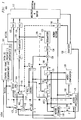
- FIG. 1 A simplified block diagram of an exemplary transform video encoder embodying aspects of the invention is shown in FIG. 1;
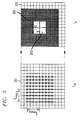
- FIG. 2 illustrates aspects of a block-matching search process between two frames;
- Shown in FIG. 3 is a weighted averaging process that occurs in an encoding system employing 2 reference frames;
- FIG. 4 shows aspects of 3-step search strategy that can be employed when using 2 reference frames;
- Shown in FIG. 5 is a portion of frame I n divided into blocks of pels;
- Illustrated in FIG. 6 is a threshold search strategy with ordered scanning;
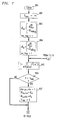
- FIGs. 7, 8, and 9 when connected together, form a flow diagram of a conjugate direction search strategy that has been extended, in accordance with an aspect of the invention, for use with 2 reference frames;
- Shown in FIG. 10, in flow chart form is a simplified composite, in accordance with an aspect of the invention, of the steps required by a motion estimator to generate motion vectors and weights for a block to be encoded.
- FIG. 1 shows, in simplified block diagram form, exemplary transform video coder 100 for encoding a sequence of image frames (frames) represented in digital form, signal VIDIN, in accordance with aspects of the invention.
- exemplary transform video coder 100 for encoding a sequence of image frames (frames) represented in digital form, signal VIDIN, in accordance with aspects of the invention.
- One aspect of the simplification is that storage elements which may be embedded in each element shown that are required for computation or sequencing and coordination purposes are not shown. However, use of such storage elements will be readily apparent to one skilled in the art.
- an overall timing and sequencing controller is not shown. Again, the use of such a timing and sequencing controller will be readily apparent to one skilled in the art.
- Transform video coder 100 supplies as an output an encoded digital data signal, BITSTREAM, that is representative of the frames of signal VIDIN with which it was supplied as an input.
- Each frame so supplied can be encoded by transform video coder 100 via one of three (3) coding methods: intraframe coding, motion predicted coding and motion predicted interpolated coding.
- Signal VIDIN is supplied as an input to control and frame rearrangement unit 101.
- Control and frame rearrangement unit 101 controls the overall operations of video coder 100 by determining via which method a frame should be encoded based on the temporal position of the frame.
- the type of encoding for any particular frame is indicated as follows: a zero (0) indicates to encode the frame with intraframe coding, a one (1) indicates to encode the frame with motion compensated prediction coding and a two (2) indicates to encode the frame with multiple frame motion interpolated coding in accordance with an aspect of the invention.
- Intraframe and motion compensated prediction coding are well know.
- Control and frame rearrangement unit 101 temporarily stores a predetermined number of frames of signal VIDIN so that the frames can be supplied as output in a different temporal order than that in which they were received.
- Each frame the structure of which is a lattice of pels each of which has a particular location, is divided into QxR blocks of pels. These pel blocks are supplied in a predetermined order as signal BLOCKS.
- Such a resequencing is employed so that the at least two reference frames which are required for motion estimation and interpolation can be processed prior to the processing of any frames which are to be motion interpolated encoded.
- the encoding type determined by control and frame rearrangement unit 101 is conveyed over first control bus 102 to switch elements 103 through 110.
- Block type unit 111 decides on a block by block basis whether a block of pels should be intraframe encoded despite the fact that the frame to which it belongs is designated to be either motion compensated predicted or motion interpolated encoded based on the temporal position of the frame in video signal VIDIN by control and frame rearrangement unit 101. Such a decision is based on block type unit 111 determining that intraframe encoding would require less bits to represent the block than the other types of encoding. To this end block type unit 111 is supplied with signal BLOCKS and the error of a reconstructed motion compensated predicted or motion interpolated version of the block with respect to the actual block, signal E, supplied by subtracter 112. Block type unit 111 controls switch elements 113 and 114 by sending commands over second control bus 115. In addition, variable length coder 116 is responsive to commands from block type unit 111 to suppress the supplying of motion vectors or weights to multiplex and buffer unit 117.
- Any element of transform video coder 100 which does not receive during the processing of a block any input that is required to generate its associated output is considered to have no operation during the processing of that block. Such inputs may not be received because of the position of one or more of switch elements 102 through 109 and switch elements 113 and 114.
- signal VIDIN is first being received after initialization of transform video coder 100 or that transform video coder 100 sends a new base frame encoded via intraframe coding at predetermined intervals and is presently so doing.
- each of switch element 103 through 110 and switch elements 113 and 114 has their arm positioned to connect to the terminal having at least a zero (0) in its associated label or if the switch has no terminal with at least a zero (0) in its associated label the position of the switch is irrelevant.
- Signal BLOCKS passes from control and frame rearrangement unit 101 through switch element 103 and 114 to discrete cosine transform unit (DCT) 119.
- DCT discrete cosine transform unit
- the QxR blocks of pels are then converted from the pel domain to the Discrete Cosine Transform domain by DCT 119.
- DCT 119 produces and supplies as an output a set of frequency coefficients that are grouped into 2-dimensional blocks of the same size as the blocks received as input.
- the transform coefficients supplied as an output by DCT 119 are then supplied to quantizer 120.
- a quantizer reduces the number of levels available for coefficients to assume.
- the quantizing can optionally be made responsive to the quantity of information stored in multiplex and buffer unit 117 via signal QNTCTRL.
- Quantized coefficients supplied as an output from quantizer 120 are in turn supplied as an input to variable length coder (VLC) 121 for encoding.
- VLC variable length coder
- Variable length coding is well known and the choice of coding methodology is at the implementor's discretion.
- the encoded representation of the quantized coefficients is supplied as an output to multiplex and buffer unit 117.
- Multiplex and buffer unit 117 subsequently supplies the encoded representation of the quantized coefficients in multiplexed fashion with the outputs of variable length coders 116 and 122 as signal BITSTREAM which may be transmitted or stored, depending on the application.
- the quantized coefficients supplied as an output from quantizer 120 are also supplied as an input to dequantizer 123 through switch element 105.
- Dequantizer 123 performs an inverse quantization on the quantized coefficients thereby generating reconstructed coefficients which are supplied to inverse discrete transform unit (IDCT) 124 to generate a reconstructed version of the block in the pel domain.
- This reconstructed block is supplied to and stored in frame buffer (F1) 125 through adder 126 and switch 106.
- Adder 126 is supplied with a null (all zero) block from null block 127.
- This first frame stored in frame buffer 125 becomes a reference frame in the past (I m ) for frames to be predicted or interpolated.
- control and frame rearrangement unit 101 Upon conclusion of processing of the first frame, control and frame rearrangement unit 101 supplies as output signal BLOCKS QxR blocks of a second frame (Ip), in the future relative to the first frame and all frames to be motion interpolated until a new base time period is selected. Additionally, under the control of control and frame rearrangement unit 101, over first control bus 102, each of switch elements 103 through 110 has their arm positioned to connect to the terminal having at least a one (1) in its associated label or if the switch has no terminal with at least a one in its label the position of the switch is irrelevant. For clarity of exposition it is assumed that all blocks in the second frame are to be motion compensated predicted and that block type unit 111 configures the arm positions of switch elements 113 and 114 accordingly to the terminal having at least a one (1) in its associated label.
- Each QxR block of pels of signal BLOCKS is supplied as input to both motion estimator 118 and subtracter 112.
- Motion estimator 118 receives the reconstructed version of the first frame from frame buffer (F1) 125 and a null block from null block 127 to derive and supply as outputs a motion vector, i.e., a displacement relative to the location of the block which identifies the location of a same size block in reference frame I m that best matches the block.
- the motion vectors for each of the blocks are supplied to motion compensator 128 via switch element 108 and to variable length coder (VLC) 116 for encoding prior to being incorporated into BIT STREAM by multiplex and buffer unit 117.
- VLC variable length coder
- Motion compensator 128 also receives the prior reconstructed frame currently stored in frame buffer (F1) 125 and generates a predicted version of the block in the current frame which is supplied through switch element 104 to subtracter 112. Subtracter 112 subtracts the predicted version of the current block from the actual current block and generates error signal E which is supplied through switch element 114 to DCT 119. DCT 119 transforms the error signal into the Discrete Cosine Transform domain and the resulting transformed error signal is supplied to and quantized by quantizer 120. The quantized transformed error signal supplied as an output from quantizer 120 are supplied as an input to variable length coder (VLC) 121 for encoding. The encoded representation of the quantized transformed error signal is supplied as an output to multiplex and buffer unit 117.
- VLC variable length coder
- the quantized transformed error signal supplied as an output from quantizer 120 are also supplied as an input to dequantizer 123 through switch element 105.
- Dequantizer 123 performs an inverse quantization on the quantized transformed error signal thereby generating reconstructed coefficients which are supplied to inverse discrete transform unit (IDCT) 124 which generates a reconstructed version of the error signal in the pel domain.
- IDCT inverse discrete transform unit
- the reconstructed version of the error signal in the pel domain is added by adder 126 to the motion predicted version of the block in the current frame received via switch element 113 to form the corrected predicted current block which very closely corresponds to the current block.
- This corrected predicted current block is supplied via switch 106 to frame buffer (F2) 130 and stored therein.
- the blocks which correspond to the current frame are accumulated in frame buffer 130 and become a reference frame in the future (I p ) for frames to be interpolated.
- the variable length encoded motion vectors and the variable length encoded quantized transformed error signals are then multiplexed together into signal BITSTREAM by multiplex and buffer unit 117 which may be transmitted or stored depending upon the application.
- Signal BITSTREAM can be employed by a corresponding decoder to reconstruct a representation of the original frame.
- each of switch elements 102 through 110 has their arm positioned to connect to the terminal having at least a two (2) in its associated label or if the switch has no terminal with a two in its label the position of the switch is irrelevant.
- block type unit 111 configures the arm positions of switch elements 113 and 114 accordingly to the terminal having at least a two (2) in its associated label.
- Each QxR block of pels of signal BLOCKS is supplied as input to both motion estimator 118 and subtracter 112.
- Motion estimator 118 receives a reconstructed version of the first (past) frame from frame buffer (F1) 125 and a reconstructed version of the second (future) frame from frame buffer (F2) 130.
- motion estimator 118 derives and supplies as an output a set of motion vectors, i.e., a set of displacements d m, d p within a predetermined area of the location of the block, wherein d m points to a same size block in the reference frame in the past I m and d p points to a same size block in the reference frame in the future I p such that a weighted sum of the values of the pels of the blocks pointed to by the displacements best approximates the block being encoded.
- the motion vectors are supplied to motion interpolator 129 via switch element 108 and to variable length coder (VLC) 116 for encoding prior to being incorporated into signal BITSTREAM by multiplex and buffer unit 117.
- Motion estimator 118 also supplies as an output to motion interpolator 129, in accordance with an aspect of the invention, a set of weighting values (weights) ⁇ m , ⁇ p for the values of the pels of the blocks pointed to by each of the motion vectors for the block, one weight corresponding with each of the motion vectors.
- Motion interpolator 129 receives the prior reconstructed frame currently stored in frame buffer (F1) 125, the reconstructed version of the second (future) frame from frame buffer (F2) 130, the motion vectors via switch element 108 and the weights via switch element 109 and generates a motion interpolated version of the block in the current frame. This motion interpolated version of the block is supplied through switch element 104 to subtracter 112.
- the interpolated version of the block in the current frame is derived by multiplying (weighting) the value of the pels of the block pointed to by the motion vector for the first (past) frame by the weight for the past frame and adding that to the value of the pels of the block pointed to by the motion vector for the second (future) frame multiplied by the value of the weight for the future frame.
- Subtracter 112 subtracts the interpolated version of the current block from the actual current block and generates error signal E which is supplied through switch element 114 to DCT 119.
- DCT 119 transforms the error signal into the Discrete Cosine Transform domain and the resulting transformed error signal is supplied to and quantized by quantizer 120.
- the quantized transformed error signal supplied as an output from quantizer 120 is supplied as an input to variable length coder (VLC) 121 for encoding.
- the encoded representation of the quantized transformed error signal is supplied as an output to multiplex and buffer unit 117.
- the weights from motion estimator 118 are supplied via switch element 109 to optional quantizer 130 which quantizes the values of the weights and supplies the quantized weight values to variable length coder 116.
- Multiplex and buffer unit 117 supplies the encoded representation of the quantized transformed error signal in multiplexed fashion with the outputs of variable length coders 116 and 122 as signal BITSTREAM which may be transmitted or stored, depending on the application.
- block type unit 111 may determine that it would require less bits to directly intraframe encode the particular block. This determination is based on a comparison of the complexity of the error signal and the actual block itself, both of which are supplied as inputs to block type unit 111. If block type unit 111 determines that it requires less bits to directly intraframe encode the particular block, switch elements 113 and 114 are instructed, via commands sent over second control bus 115, to connect to the terminal having a zero label.
- variable length coder 116 is responsive to commands from block type unit 111 to suppress the supplying of motion vectors and weights to multiplex and buffer unit 117. This results in the selected block being intraframe encoded, as described above.
- Block type unit 111 supplies an indication of the type of encoding selected. This indication is itself encoded by variable length coder 122 and supplied to multiplex and buffer unit 117 where it is appropriately incorporated into signal BITSTREAM. If the block was to have been motion compensated predicted, a reconstructed version of the block in the pel domain will be generated as described above for blocks of a frame that was to be intraframe encoded. However, the reconstructed version of the block in the pel domain will be stored in frame buffer 130, instead of in frame buffer 125, because of the position of switch element 106.
- control and frame rearrangement unit 101 determines that all the frames between the first (past) and second (future) frames have been encoded, switch element 110 is closed and the image frame stored in frame buffer 130, which is the future image frame, is copied into frame buffer 125 to become the new past image frame. Thereafter, a new future frame, further in the future than the old future frame, will be motion compensated predicted and stored in frame buffer F2.
- two new reference frames could be selected by control and frame rearrangement unit 101, the first of which would be intraframe encoded and stored in frame buffer 125 and the second of which would be motion compensated predicted and stored in the frame buffer 130. The interpolation process would continue thereafter as described above for all frames between the selected reference frames.
- Shown in FIG. 2 are exemplary sets of pels 201 and 202 from the same representative area of the image lattice of each of frames I m and I p from signal VIDIN (FIG. 1). These frames correspond to the first and second frames processed by video coder 100.
- I m is a reference frame in the past relative to frame I p which is to be encoded by motion compensated prediction by video encoder 100.
- Block of pels 203, a QxR subset of set of pels 201 is the block for which a search is to be performed.
- a typical value for each of Q and R is 16. However, for clarity and brevity of exposition, Q and R are each shown in FIG. 2 as having a value of 4.
- a search range is the maximum individual component of distance (typically in units of pels), in either the horizontal or vertical direction, for any displacement that is a candidate to be motion vector.
- the total search area defined by the search range is graphically depicted via the sum of the gray shaded region 204 and block 203.
- the total search area is a region which indicates the potential area in which to find each pel of a candidate block to approximate block 203.
- the locations in previous frame 202 marked by an X defines the set of centers of potential blocks in frame 202 which will be searched for the best possible match to block 203.
- the distance from the center of block 203 to a location marked by an X in frame 202 corresponds to a displacement which is a candidate to be a motion vector for block 203.
- the matching function defined in equation (1) is computed for each displacement defined by a center location in previous frame 202 marked by an X.
- the motion vector corresponds to the displacement d at which the minimum of the matching function is found, which is the "best candidate".
- FIG. 3 the operation of FIG. 2 is generalized to two reference frames, in accordance with an aspect of the invention.
- Frame I n is to be encoded via motion interpolation by video encoder 100.
- I m is a reference frame in the past relative to frame I n
- I p is a reference frame in the future relative to frame I n .
- Block of pels 302, a QxR subset of set of pels 301, is the block to be encoded. It is for block 302 that a search for motion vectors and corresponding weights is to be performed.
- the reference frames are typically arranged such that one is in the past (I m ) and one is in the future (I p ) relative to frame I n which is to be encoded by motion interpolation, as shown in FIG. 3 by representative sets of pels 201, 202 and 301. However, at the implementor's discretion, both reference frames (I m and I p ) may be in the past relative to frame I n .
- the displacements pointing to a block of pels in each of frames I m and I p must be found by motion estimator 118 (FIG. 1) such that the weighted combination of values of the pels comprising the blocks pointed to the energy of the error signal (E) is minimized.
- E( x' ) I n ( x' )-( ⁇ m I m ( x' + d m )+ ⁇ p I p ( x' + d p )) (3) is the error for d m ⁇ D m and d p ⁇ D p .
- d m and d p are the displacements for frame I m and I p .
- a candidate pair of values for d m and d p are graphically depicted in FIG. 3 as vectors 303 and 304, respectively.
- D m and D p correspond to the search ranges, respectively, in frames frame I m and I p .
- the respective search areas defined by D m and D p are graphically illustrated by shaded regions 305 and 306.
- ⁇ m and ⁇ p are the weighting factors accorded to each pel value of the respective blocks to be combined from frames 201 and 202.
- the determination of optimum displacements and weights is achieved by imposing that the partial derivatives of with respect to ⁇ m and ⁇ p equal zero.
- d m , d p requires a search among a set of candidate displacement pairs. Typically, all the pairs of displacements that are confined within the search range are included in the set of candidate displacement pairs. For each member of a set of candidate displacement pairs matrices M , M ⁇ 1 and vector v are evaluated so that equation (8) is yields particular values for u *. The values of u * and their corresponding displacement pair d m , d p are then employed, in accordance with an aspect of the invention, to compute the energy of E.
- the n-tuple ( ⁇ * m , ⁇ * p , d m , d p ) of a particular displacement pair is stored if it yields a smaller value of the E energy than any other displacement pair already evaluated during the search.
- the E energy of the stored n-tuple is also stored, so that as the E energy of each subsequent n-tuple is evaluated it can quickly be compared with the E energy of the stored n-tuple.
- the n-tuple that remains stored when all the candidate pairs of displacements have been evaluated is comprised of the optimum weights and displacements for the block being encoded. These are supplied by motion estimator 118 (FIG.
- One such method in accordance with an aspect of the invention, is to interrupt the search procedure and utilize a particular d m , d p whenever the energy of the E signal falls below a predetermined threshold T.
- This method finds a value of the energy of the E signal which, although perhaps not the absolute minimum, is acceptably small and yet tends to limit the number displacement pairs d m , d p that must be checked. This is because once an acceptably small value for the energy of E is obtained, none of the remaining candidate displacement pairs d m , d p need be checked.
- the speed at which a search that employs a threshold finds a displacement pair that satisfies the threshold may be further increased by controlling the order in which the candidate pairs are evaluated.
- the selection of which displacement pairs become members of the set of candidate pairs can also be controlled so as to limit the number of candidate pairs to be evaluated.
- Candidate pairs may be added or removed from the set of candidate pairs depending on the results of prior candidate pair evaluations. Control of the selection of the displacement pairs can also be combined with a threshold criterion
- One exemplary method limits the process of searching for the optimum weights and displacements by controlling the candidate pairs which are added to and removed from the set of candidate pairs relies on the fact that the energy of E decreases monotonically as the displacement moves away from the direction of minimum distortion.
- Shown in FIG. 4 is exemplary sets of pels 201, 202 and 301 from the same areas of frames I m , I p and I n .
- Block 401 corresponds to the block of interest, as it is situated in the lattice of frame I n , which is to be interpolated.
- the following exemplary sequence of steps may be employed to search for an acceptable pair of displacements for use as motion vectors, in accordance with an aspect of the invention.
- Each displacement is defined with respect to a location relative to a coordinate origin pointed to by x .
- origin 402 is indicated by a cross is at the center of block 401.
- All displacements corresponding to the null (0,0) displacement and those defined by predetermined locations in each of frames I m and I p that are substantially equidistant from x , e.g., the center of block 401, by approximately one quarter of the distance of the total search area are selected as a set of initial candidate displacements.
- Each member of the set of locations 404 selected is marked in FIG. 4 by at least an X .
- a set of pairs defined by the pairwise combination of all the selected displacements having one displacement defined by a location in frame I m and one displacement defined by a location in frame I p is determined.
- 81 candidate pairs of displacements will be members of the set of pairs.
- the minimum E energy is computed for each candidate pair of the set of pairs.
- the displacement pair with the minimum E energy is designated d and d .
- This selected displacement pair has one displacement defined by a location in frame I m and a second displacement defined by a location in frame I p .
- the pair of locations 405 defining d and d in this example pair of locations 405, is marked by both an X and a filled square in each of set of pels 201 and 202.
- the displacements defined by locations 405, i.e., d and d , and those displacements defined by predetermined locations in each of frames I m and I p that are substantially equidistant from each location of set of locations 405 by approximately one eighth of the distance of the total search area are selected as a new set of candidate displacements.
- the total set of locations 406 selected are marked in FIG.
- a second set of pairs defined by the pairwise combination of all such selected displacements having one displacement defined by a location in frame I m and one displacement defined by a location in frame I p is determined.
- the minimum E energy is computed for each candidate pair of the second set of pairs.
- the pair with the minimum E energy is designated d , d .
- This selected displacement pair has one displacement defined by a location in frame I m and a second displacement defined by a location in frame I p .
- the defining point of each displacement of the selected displacement pair with minimum E energy in this example is set of locations 407, location of which is marked by both a filled square and a circle in each of set of pels 201 and 202.
- the displacements defined by locations 407, i.e., d and d , and those displacements defined by predetermined locations in each of frames I m and I p that are substantially equidistant from each location of set of locations 407 by approximately one sixteenth of the distance of the total search area are selected as the final set of candidate displacements.
- Each location of the total set of locations 408 selected is marked in FIG.
- a third set of pairs defined by the pairwise combination of all such selected displacements having one displacement defined by a location in frame I m and one displacement defined by a location in frame I p is determined.
- 81 candidate pairs of displacements will be members of this third set of pairs.
- the minimum E energy is computed for each candidate pair of the third set of pairs.
- the pair with the minimum E energy is designated d , d .
- This selected displacement pair has one displacement defined by a location in frame I m and a second displacement defined by a location in frame I p .
- each displacement of the selected displacement pair with minimum E energy is marked by both a filled circle in each of set of pels 201 and 202.
- This selected displacement pair having one displacement defined by a location in frame I m and a second displacement defined by a location in frame I p is selected as the motion vectors for block 402.
- this procedure for searching for a displacement pair to use as a motion vector should terminate whenever the E energy becomes equal to or less than a threshold value T.
- the displacement pair which first to achieves an E energy less than T is chosen as the motion vectors.
- additional search steps could be added, as will be understood by one skilled in the art, depending upon the block size chosen and the error margin acceptable to the implementor.
- Another exemplary method for reducing the number candidate displacement pairs that need be checked to find a pair of motion vectors and their corresponding weights employs information concerning spatially neighboring blocks and individual pels, in accordance with an aspect of the invention, for arranging the displacement pairs that are members of the set of displacement candidates.
- the arrangement strategy is based on the generally true proposition that all blocks in a particular area of a frame are likely to be part of a single object which is moving. Therefore, all the blocks of which the object is comprised are initially presumed moving in a substantially uniform manner from frame to frame. Shown in FIG. 5 is a portion of a frame I n to be encoded by video coder 100 (FIG. 1) as it is divided into blocks of pels by control and frame rearrangement unit 101.
- Blocks of pels 501 and 502 are located at x (01) and x (10) in frame I n which are located, respectively, to the left and above block 503 located at x (00) and which is currently to be encoded.
- the optimal set of displacement pairs i.e., the motion vectors, are denoted for blocks 501 and 502 by respectively.
- an initial displacement pair either A or B, is chosen for block 503, denoted by The choice of which initial displacement pair A or B to assign to C is made by determining which pair will have minimum E energy and assigning the determined pair.
- the estimation of the motion of block 503 represented in the displacement pair assigned as the motion vector may be further improved by searching through additional pairs of candidate displacements.
- a searching method with a threshold strategy is employed so that all candidate displacement pairs within the search range having one displacement in each of frames I m and I p are scanned such that the motion vectors selected are a displacement pair having the lowest E energy for values of the displacements close to the values of C.
- a further exemplary search limitation method employs an approach that alternately switches the frame being searched for a motion vector between reference frames I m and I p , i.e., when d m is fixed, d p is changed, and vice-versa.
- a method is termed a ping-pong search.
- the reference frame that is chosen to be fixed initially is the one temporally closest to frame I n , the frame to be motion interpolated encoded, as there is more confidence in its neighboring block initial estimate.
- One of two scanning orders may be employed.
- the initial displacements selected as C are renamed d m,0 and d p,0 , i.e.
- Block of pels 601 in frame I m and block of pels 602 in I p correspond in location to block of pels 503 of frame I n .
- Displacement pair 603 is initially assigned to C. For ease of exposition, it is assumed that d p is initially fixed. All values of displacements d m that are combined in a pair with d p,0 are scanned in a circular fashion around d m,0 . The order in which candidate displacements are selected for the exemplary search, depicted in FIG.
- conjugate direction search is extended, in accordance with an aspect of the invention, as another method of increasing the speed of the search of candidate displacements by determining the order in which members of the set of candidate displacements are searched in the finding of motion vectors. For purposes of this example, all the pairs of displacements that are confined within the search range are included in the set of candidate displacement pairs.
- FIGs. 7, 8, and 9, in flow chart form is an exemplary implementation of the extended conjugate direction search.
- the routine is executed by motion interpolator 129 (FIG. 1) and it is entered via step 801 when a set of displacements to be used as motion vectors is needed for a block.
- S min the current minimum energy of E, is initialized to infinity.
- step 803 the displacement with respect to a first reference frame, in this example frame I m , is defined to have the same row value as the initial displacement selected for C as defined above and whose column value is set to the leftmost column displacement defined by a search range D max .
- the displacement with respect to a second reference frame, in this example frame I p is defined to have the same row value as the initial displacement selected for C and whose column value is set to the leftmost column displacement defined by the search range D max .
- row flag px_flag is set to be a one. It is recognized that the rightmost and leftmost directions can be uniformly interchanged for purposes of the search. Similarly, the upmost and downmost directions can be uniformly interchanged for purposes of the search. Additionally, row and column order can be uniformly interchanged for purposes of the search. The directions in this example were selected for convenience purposes only.
- step 805 the energy of E is computed for the current pair of displacement values and is denoted S.
- conditional branch point 806 tests if S is less than S min .
- step 807 sets the following values: change_min, a flag indicating that S min has been changed is set to 1; d m,min , a variable that contains the current estimate of the displacement in frame I m , is set to d m ; d p,min , a variable that contains the current estimate of the displacement in frame I p , is set to d p ; and S min is set to the current value of S.
- Control is then passed to conditional branch point 808. If the test result in step 806 is NO, control is passed directly to step 808.
- Conditional branch point 808 tests if px_flag is set to 1.
- control is passed to conditional branch point 809 which tests if d p,x is equal to the downmost row value D max,x . If the test result in step 809 is NO, control is passed to step 810 which increments the row value of displacement d p . Control is then passed back to step 805 to determine and test the new values of S. If the test result in step 809 is YES, control is passed to conditional branch point 811 which tests if flag change_min is set to one. If the test result in step 811 is YES, control is passed to step 812 which sets the new d p estimate to the row displacement found to have the minimum S and the leftmost column displacement. Additionally, flag change_min is set to zero (0) and px_flag is set to 1. Then control is passed back to step 805.
- step 808 If the test result in step 808 is YES, control is passed to step 813 which tests if d p,y is equal to the rightmost column displacement. If the test result in step 813 is NO, control is passed to step 814 which increments the column value of displacement d p . Control is then passed back to step 805 to determine and test the new values of S. If the test result in step 813 is YES, control is passed to step 815 which tests if flag change_min is set to 1.
- step 815 If the test result in step 815 is YES, control is passed to step 816 which sets the new d p estimate to the column displacement found to have the minimum S and the topmost row displacement Additionally, flag change_min is set to zero (0) and px_flag is set to zero (0). Then control is passed back to step 805.
- conditional branch point 817 tests if mx_flag is set to 1. If the test result in step 817 is NO, control is passed to conditional branch point 818 which tests if d m,x is equal to the downmost row value D max,x . If the test result in step 818 is NO, control is passed to step 819 which increments the row value of displacement d m . Control is then passed back to step 805 to determine and test the new values of S. If the test result in step 818 is YES, control is passed to conditional branch point 820 which tests if flag change_min is set to one.
- step 820 If the test result in step 820 is YES, control is passed to step 821 which sets the new d m estimate to the row displacement found to have the minimum S and the leftmost column displacement. Additionally, flag change_min is set to zero (0) and mx_flag is set to 1. Then control is passed back to step 805.
- step 817 If the test result in step 817 is YES, control is passed to step 822 which tests if d m,y is equal to the rightmost column displacement. If the test result in step 822 is NO, control is passed to step 823 which increments the column value of displacement d m . Control is then passed back to step 805 to determine and test the new values of S. If the test result in step 822 is YES, control is passed to step 824 which tests if flag change_min is set to 1. If the test result in step 824 is YES, control is passed to step 825 which sets the new d m estimate to the column displacement found to have the minimum S and the topmost row displacement.
- step 827 If the test results in steps 820 or 824 were NO the current values of displacements d m,min and d p,min are returned via step 826. Thereafter, the routine is exited via step 827.
- a limited set of displacements for example 3 or 5, could be compared in each direction, rather than [2
- the number of possible pair of displacements to consider is reduced from ([2
- Equation (12) does not contain any values taken from frame I n . This ensures that a decoder can estimate the quantization step sizes for ⁇ m and ⁇ p directly from a reconstruction of frames I m and I p as long the maximum acceptable E energy increase due to quantization ⁇ max is known.
- FIG. 10 Shown in FIG. 10, in flow chart form, is a simplified composite, in accordance with an aspect of the invention, of the steps required of motion estimator 118 (FIG. 1) to generate motion vectors and weights for a block to be encoded.
- the routine is entered in step 1001 when it is determined that motion vectors and weights are to be generated.
- the current value stored for the error energy E stored is initialized to infinity.
- candidate displacements are determined for each reference frame.
- Step 1007 groups the candidate displacements into a set of groups d m , d p .
- the next d m , d p group to be processed is obtained from the set of groups.
- step 1011 M ⁇ 1 and a vector v are evaluated for the d m , d p group.
- the error energy for ⁇ * m , ⁇ * p , d m , d p is computed in step 1015.
- conditional branch point 1017 tests to determine if the E energy is less than the current value of E stored . If the test result in step 1017 is YES control is passed to step 1019 which stores ⁇ * p , ⁇ * m , d m , d p and sets E stored equal to the current E energy. Control is then passed to step 1021.
- step 1021 If the test result in step 1017 is NO, control is passed directly to step 1021.
- Conditional branch point 1021 tests to determine if E stored is less than threshold T. If the test result in step 1021 is NO control is passed to step 1023 which readjusts the set of d m , d p groups. This readjustment can be a rearrangement of the order in which the groups are selected in step 1009, an addition or a deletion of groups from the set, whichever is required for an efficient search. Control is then passed to step 1027. If the test result in step 1021 is YES control is passed to step 1025 which removes all remaining d m , d p groups from the set of groups, thereby leaving no remaining groups to be processed. Control is then passed to step 1027.
- Conditional branch point 1027 tests to determine if there are any more d m , d p groups remaining in the set of groups which need to be processed. If the test result in step 1027 is YES, control is passed back to step 1009 to get another group to be processed. If the test result in step 1027 is NO, control is passed to step 1029 for the performance of any optional quantization. Such quantization may actually be performed by quantizer 130. Control is then passed to step 1031 and the routine is exited. The final stored values of ⁇ * m , ⁇ * p ,d m , d p are available to be supplied as the motion vectors and corresponding optional weights. It will be recognized by persons skilled in the art that the above described invention may be employed on each component of a composite signal.
Landscapes
- Engineering & Computer Science (AREA)
- Multimedia (AREA)
- Signal Processing (AREA)
- Physics & Mathematics (AREA)
- General Physics & Mathematics (AREA)
- Theoretical Computer Science (AREA)
- Computer Vision & Pattern Recognition (AREA)
- Compression Or Coding Systems Of Tv Signals (AREA)
- Image Processing (AREA)
- Color Television Systems (AREA)
Applications Claiming Priority (2)
| Application Number | Priority Date | Filing Date | Title |
|---|---|---|---|
| US693878 | 1991-04-30 | ||
| US07/693,878 US5151784A (en) | 1991-04-30 | 1991-04-30 | Multiple frame motion estimation |
Publications (2)
| Publication Number | Publication Date |
|---|---|
| EP0511778A2 true EP0511778A2 (fr) | 1992-11-04 |
| EP0511778A3 EP0511778A3 (en) | 1994-09-21 |
Family
ID=24786491
Family Applications (1)
| Application Number | Title | Priority Date | Filing Date |
|---|---|---|---|
| EP19920303631 Withdrawn EP0511778A3 (en) | 1991-04-30 | 1992-04-23 | Multiple frame motion estimation |
Country Status (4)
| Country | Link |
|---|---|
| US (1) | US5151784A (fr) |
| EP (1) | EP0511778A3 (fr) |
| JP (1) | JP2665109B2 (fr) |
| KR (1) | KR960001517B1 (fr) |
Cited By (16)
| Publication number | Priority date | Publication date | Assignee | Title |
|---|---|---|---|---|
| US5510856A (en) * | 1994-12-30 | 1996-04-23 | Daewoo Electronics Co., Ltd. | Apparatus for determining motion vectors |
| EP0720355A1 (fr) * | 1994-12-30 | 1996-07-03 | Daewoo Electronics Co., Ltd | Appareil pour déterminer des déplacements de vecteurs à l'aide d'un filtre médian adaptif |
| WO2005004492A3 (fr) * | 2003-06-25 | 2005-04-14 | Thomson Licensing Sa | Procede et appareil mettant en oeuvre une estimation de prediction ponderee au moyen d'un differentiel d'images deplacees |
| EP1405425A4 (fr) * | 2001-07-11 | 2006-02-08 | Dolby Lab Licensing Corp | Interpolation de schémas de compression vidéo |
| EP1827028A1 (fr) * | 2002-01-18 | 2007-08-29 | Kabushiki Kaisha Toshiba | Procédé et appareil de codage vidéo et procédé et appareil de décodage vidéo |
| US7266150B2 (en) | 2001-07-11 | 2007-09-04 | Dolby Laboratories, Inc. | Interpolation of video compression frames |
| EP1234447A4 (fr) * | 1999-11-05 | 2008-03-12 | Dolby Lab Licensing Corp | Systeme et procede de compensation du mouvement et de conversion de la frequence des trames |
| US7428639B2 (en) | 1996-01-30 | 2008-09-23 | Dolby Laboratories Licensing Corporation | Encrypted and watermarked temporal and resolution layering in advanced television |
| US7720152B2 (en) | 2002-10-01 | 2010-05-18 | Thomson Licensing | Implicit weighting of reference pictures in a video decoder |
| US7801217B2 (en) | 2002-10-01 | 2010-09-21 | Thomson Licensing | Implicit weighting of reference pictures in a video encoder |
| US7903742B2 (en) | 2002-07-15 | 2011-03-08 | Thomson Licensing | Adaptive weighting of reference pictures in video decoding |
| US7961784B2 (en) | 2001-07-12 | 2011-06-14 | Dolby Laboratories Licensing Corporation | Method and system for improving compressed image chroma information |
| US8111754B1 (en) | 2001-07-11 | 2012-02-07 | Dolby Laboratories Licensing Corporation | Interpolation of video compression frames |
| US8290051B2 (en) | 2002-07-15 | 2012-10-16 | Thomson Licensing | Adaptive weighting of reference pictures in video encoding |
| US8374237B2 (en) | 2001-03-02 | 2013-02-12 | Dolby Laboratories Licensing Corporation | High precision encoding and decoding of video images |
| US9667993B2 (en) | 2008-08-04 | 2017-05-30 | Dolby Laboratories Licensing Corporation | Predictive motion vector coding |
Families Citing this family (70)
| Publication number | Priority date | Publication date | Assignee | Title |
|---|---|---|---|---|
| GB9015426D0 (en) * | 1990-07-13 | 1990-08-29 | Indep Broadcasting Authority | Error protection for variable length codestreams |
| JP2833236B2 (ja) * | 1991-01-31 | 1998-12-09 | 日本電気株式会社 | 画像の予測符号化方式 |
| SE469866B (sv) * | 1991-04-12 | 1993-09-27 | Dv Sweden Ab | Metod för estimering av rörelseinnehåll i videosignaler |
| JP3093499B2 (ja) * | 1992-03-06 | 2000-10-03 | 三菱電機株式会社 | シーンチェンジ検出装置 |
| DE69322423T2 (de) * | 1992-03-13 | 1999-06-02 | Canon K.K., Tokio/Tokyo | Vorrichtung zur Detektion von Bewegungsvektoren |
| GB2266023B (en) * | 1992-03-31 | 1995-09-06 | Sony Broadcast & Communication | Motion dependent video signal processing |
| JPH0622301A (ja) * | 1992-06-30 | 1994-01-28 | Sony Corp | 画像符号化装置 |
| US5568569A (en) * | 1992-12-31 | 1996-10-22 | Intel Corporation | Method and apparatus for analyzing digital video images by merging displacement vectors |
| WO1994018799A1 (fr) * | 1993-02-03 | 1994-08-18 | Qualcomm Incorporated | Systeme de codage et de decodage video entre images |
| US6266372B1 (en) * | 1993-03-31 | 2001-07-24 | Canon Kabushiki Kaisha | Apparatus for image reproduction using motion estimation |
| US5329318A (en) * | 1993-05-13 | 1994-07-12 | Intel Corporation | Method for optimizing image motion estimation |
| JP2636674B2 (ja) * | 1993-05-25 | 1997-07-30 | 日本電気株式会社 | 動画像の動きベクトル検出装置 |
| US5684534A (en) * | 1993-05-26 | 1997-11-04 | Intel Corporation | Task-splitting dual-processor system for motion estimation processing |
| EP0709009A1 (fr) * | 1993-06-16 | 1996-05-01 | GOULD, Kim V.W. | Systeme et procede de transmission de donnees video |
| JPH07135663A (ja) * | 1993-09-17 | 1995-05-23 | Oki Electric Ind Co Ltd | 動きベクトル検出方法および動きベクトル検出装置 |
| JP2590705B2 (ja) * | 1993-09-28 | 1997-03-12 | 日本電気株式会社 | 動き補償予測装置 |
| US5473379A (en) | 1993-11-04 | 1995-12-05 | At&T Corp. | Method and apparatus for improving motion compensation in digital video coding |
| US5438374A (en) * | 1993-12-10 | 1995-08-01 | At&T Corp. | System and method for filtering video signals |
| US5537155A (en) * | 1994-04-29 | 1996-07-16 | Motorola, Inc. | Method for estimating motion in a video sequence |
| KR100287211B1 (ko) * | 1994-08-30 | 2001-04-16 | 윤종용 | 양방향 움직임 추정방법 및 장치 |
| KR0178231B1 (ko) * | 1995-08-10 | 1999-05-01 | 배순훈 | 계층적인 움직임 추정 기법을 이용하는 움직임 벡터 검출 방법 및 장치 |
| US5706059A (en) * | 1994-11-30 | 1998-01-06 | National Semiconductor Corp. | Motion estimation using a hierarchical search |
| US5627601A (en) * | 1994-11-30 | 1997-05-06 | National Semiconductor Corporation | Motion estimation with bit rate criterion |
| US5644361A (en) * | 1994-11-30 | 1997-07-01 | National Semiconductor Corporation | Subsampled frame storage technique for reduced memory size |
| US5550595A (en) * | 1994-12-16 | 1996-08-27 | Intel Corporation | Apparatus and method for motion estimation with enhanced camera interface |
| KR0154920B1 (ko) * | 1994-12-30 | 1998-11-16 | 배순훈 | 동영상 부호화 장치에 있어서 움직임 추정기 |
| US6020926A (en) * | 1994-12-30 | 2000-02-01 | Intel Corporation | Motion estimation block matching speedup |
| US5619268A (en) * | 1995-01-17 | 1997-04-08 | Graphics Communication Laboratories | Motion estimation method and apparatus for calculating a motion vector |
| DE69619002T2 (de) * | 1995-03-10 | 2002-11-21 | Kabushiki Kaisha Toshiba, Kawasaki | Bildkodierungs-/-dekodierungsvorrichtung |
| US5943096A (en) | 1995-03-24 | 1999-08-24 | National Semiconductor Corporation | Motion vector based frame insertion process for increasing the frame rate of moving images |
| US5691775A (en) * | 1995-03-30 | 1997-11-25 | Intel Corporation | Reduction of motion estimation artifacts |
| US5818969A (en) * | 1995-05-12 | 1998-10-06 | Intel Corporation | Intelligent start for motion estimation search |
| US5703966A (en) * | 1995-06-27 | 1997-12-30 | Intel Corporation | Block selection using motion estimation error |
| US5751861A (en) * | 1995-06-30 | 1998-05-12 | Intel Corporation | Reducing residual artifacts in video coding schemes with integer motion compensation |
| US5687097A (en) * | 1995-07-13 | 1997-11-11 | Zapex Technologies, Inc. | Method and apparatus for efficiently determining a frame motion vector in a video encoder |
| US5886744A (en) * | 1995-09-08 | 1999-03-23 | Intel Corporation | Method and apparatus for filtering jitter from motion estimation video data |
| US5623313A (en) * | 1995-09-22 | 1997-04-22 | Tektronix, Inc. | Fractional pixel motion estimation of video signals |
| US5706054A (en) * | 1995-12-01 | 1998-01-06 | Intel Corporation | Method and apparatus for adjusting video data to limit the effects of automatic focusing control on motion estimation video coders |
| US5715176A (en) * | 1996-01-23 | 1998-02-03 | International Business Machines Corporation | Method and system for locating a frame position in an MPEG data stream |
| US5661524A (en) * | 1996-03-08 | 1997-08-26 | International Business Machines Corporation | Method and apparatus for motion estimation using trajectory in a digital video encoder |
| GB2311184A (en) * | 1996-03-13 | 1997-09-17 | Innovision Plc | Motion vector field error estimation |
| ATE189353T1 (de) * | 1996-04-18 | 2000-02-15 | Nokia Mobile Phones Ltd | Videodatenkodierer und -dekodierer |
| KR100209413B1 (ko) * | 1996-05-23 | 1999-07-15 | 전주범 | 블럭-기반 비디오 신호 부호화 시스템에 이용하기 위한그리드 결정방법 |
| CN1217852A (zh) * | 1997-02-13 | 1999-05-26 | 三菱电机株式会社 | 动态图象预测方式 |
| US6348946B1 (en) | 1997-08-14 | 2002-02-19 | Lockheed Martin Corporation | Video conferencing with video accumulator array VAM memory |
| US6249318B1 (en) * | 1997-09-12 | 2001-06-19 | 8×8, Inc. | Video coding/decoding arrangement and method therefor |
| US6014181A (en) * | 1997-10-13 | 2000-01-11 | Sharp Laboratories Of America, Inc. | Adaptive step-size motion estimation based on statistical sum of absolute differences |
| US6895051B2 (en) * | 1998-10-15 | 2005-05-17 | Nokia Mobile Phones Limited | Video data encoder and decoder |
| US6411652B1 (en) * | 1998-10-23 | 2002-06-25 | International Business Machines Corp. | Motion estimation |
| US7885336B2 (en) * | 2001-02-05 | 2011-02-08 | Ati Technologies Ulc | Programmable shader-based motion compensation apparatus and method |
| US6873735B1 (en) | 2001-02-05 | 2005-03-29 | Ati Technologies, Inc. | System for improved efficiency in motion compensated video processing and method thereof |
| US6687301B2 (en) * | 2001-03-19 | 2004-02-03 | Fulvio Moschetti | Method for block matching motion estimation in digital video sequences |
| FR2828977B1 (fr) * | 2001-08-21 | 2003-12-05 | Nextream Sa | Dispositif et procede d'estimation du niveau de bruit, systeme de reduction de bruit et systeme de codage comprenant un tel dispositif |
| US20030059089A1 (en) * | 2001-09-25 | 2003-03-27 | Quinlan James E. | Block matching at the fractional pixel level for motion estimation |
| EP1489848A4 (fr) * | 2002-03-14 | 2006-05-03 | Matsushita Electric Industrial Co Ltd | Procede de detection de vecteur de mouvement |
| DE10225434B4 (de) * | 2002-06-07 | 2004-12-30 | Siemens Ag | Verfahren und Vorrichtung zur Videocodierung |
| EP1422928A3 (fr) * | 2002-11-22 | 2009-03-11 | Panasonic Corporation | Interpolation pour un signal vidéo numérique avec compensation de mouvement |
| US20050201462A1 (en) * | 2004-03-09 | 2005-09-15 | Nokia Corporation | Method and device for motion estimation in scalable video editing |
| CN1957614B (zh) * | 2004-05-25 | 2010-04-14 | Nxp股份有限公司 | 在隔行扫描的视频图像中的运动估计 |
| JP3880985B2 (ja) * | 2004-08-05 | 2007-02-14 | 松下電器産業株式会社 | 動きベクトル検出装置および動きベクトル検出方法 |
| KR100723403B1 (ko) * | 2005-02-28 | 2007-05-30 | 삼성전자주식회사 | 컬러 성분간 단일 부호화 모드를 이용한 예측영상 생성 방법 및 장치와, 그를 이용한 영상 및 비디오 부호화/복호화방법 및 장치 |
| JP4752631B2 (ja) * | 2006-06-08 | 2011-08-17 | 株式会社日立製作所 | 画像符号化装置、及び画像符号化方法 |
| JP5008431B2 (ja) * | 2007-03-15 | 2012-08-22 | キヤノン株式会社 | 画像処理装置及び画像処理方法 |
| US8804821B2 (en) * | 2008-09-26 | 2014-08-12 | Microsoft Corporation | Adaptive video processing of an interactive environment |
| US9042680B2 (en) * | 2009-02-12 | 2015-05-26 | Zoran (France) S.A. | Temporal video interpolation method with 2-frame occlusion handling |
| TWI466550B (zh) | 2011-02-23 | 2014-12-21 | Novatek Microelectronics Corp | 多媒體裝置及其移動偵測方法 |
| US9762904B2 (en) | 2011-12-22 | 2017-09-12 | Qualcomm Incorporated | Performing motion vector prediction for video coding |
| TW201406166A (zh) * | 2012-07-27 | 2014-02-01 | Novatek Microelectronics Corp | 視訊編碼方法與視訊編碼裝置 |
| US9990536B2 (en) | 2016-08-03 | 2018-06-05 | Microsoft Technology Licensing, Llc | Combining images aligned to reference frame |
| KR102615156B1 (ko) * | 2018-12-18 | 2023-12-19 | 삼성전자주식회사 | 감소된 개수의 후보 블록들에 기초하여 모션 추정을 수행하는 전자 회로 및 전자 장치 |
Family Cites Families (4)
| Publication number | Priority date | Publication date | Assignee | Title |
|---|---|---|---|---|
| CA1287161C (fr) * | 1984-09-17 | 1991-07-30 | Akihiro Furukawa | Dispositif pour distinguer les parties en mouvement des parties stationnaires dans les images video |
| US4985768A (en) * | 1989-01-20 | 1991-01-15 | Victor Company Of Japan, Ltd. | Inter-frame predictive encoding system with encoded and transmitted prediction error |
| JPH07112283B2 (ja) * | 1989-02-14 | 1995-11-29 | 日本ビクター株式会社 | 動きベクトル検出装置及び検出方法 |
| US4958226A (en) * | 1989-09-27 | 1990-09-18 | At&T Bell Laboratories | Conditional motion compensated interpolation of digital motion video |
-
1991
- 1991-04-30 US US07/693,878 patent/US5151784A/en not_active Expired - Lifetime
-
1992
- 1992-04-23 KR KR92006843A patent/KR960001517B1/ko not_active Expired - Fee Related
- 1992-04-23 EP EP19920303631 patent/EP0511778A3/en not_active Withdrawn
- 1992-04-27 JP JP4131395A patent/JP2665109B2/ja not_active Expired - Fee Related
Cited By (94)
| Publication number | Priority date | Publication date | Assignee | Title |
|---|---|---|---|---|
| US5510856A (en) * | 1994-12-30 | 1996-04-23 | Daewoo Electronics Co., Ltd. | Apparatus for determining motion vectors |
| EP0720356A1 (fr) * | 1994-12-30 | 1996-07-03 | Daewoo Electronics Co., Ltd | Appareil pour déterminer des déplacessents de vecteurs |
| EP0720355A1 (fr) * | 1994-12-30 | 1996-07-03 | Daewoo Electronics Co., Ltd | Appareil pour déterminer des déplacements de vecteurs à l'aide d'un filtre médian adaptif |
| US5539469A (en) * | 1994-12-30 | 1996-07-23 | Daewoo Electronics Co., Ltd. | Apparatus for determining motion vectors through the use of an adaptive median filtering technique |
| US7428639B2 (en) | 1996-01-30 | 2008-09-23 | Dolby Laboratories Licensing Corporation | Encrypted and watermarked temporal and resolution layering in advanced television |
| EP1234447A4 (fr) * | 1999-11-05 | 2008-03-12 | Dolby Lab Licensing Corp | Systeme et procede de compensation du mouvement et de conversion de la frequence des trames |
| US8374237B2 (en) | 2001-03-02 | 2013-02-12 | Dolby Laboratories Licensing Corporation | High precision encoding and decoding of video images |
| US10264256B2 (en) | 2001-03-02 | 2019-04-16 | Dolby Laboratories Licensing Corporation | High precision encoding and decoding of video images |
| US8488670B2 (en) | 2001-03-02 | 2013-07-16 | Dolby Laboratories Licensing Corporation | High precision encoding and decoding of video images |
| US8576907B2 (en) | 2001-03-02 | 2013-11-05 | Dolby Laboratories Licensing Corporation | High precision encoding and decoding of video images |
| US8594188B2 (en) | 2001-03-02 | 2013-11-26 | Dolby Laboratories Licensing Corporation | High precision encoding and decoding of video images |
| US9667957B2 (en) | 2001-03-02 | 2017-05-30 | Dolby Laboratories Licensing Corporation | High precision encoding and decoding of video images |
| US10080035B2 (en) | 2001-07-11 | 2018-09-18 | Dolby Laboratories Licensing Corporation | Interpolation of video compression frames |
| US8325809B2 (en) | 2001-07-11 | 2012-12-04 | Dolby Laboratories Licensing Corporation | Interpolation of video compression frames |
| US9788012B2 (en) | 2001-07-11 | 2017-10-10 | Dolby Laboratories Licensing Corporation | Interpolation of video compression frames |
| US8144774B2 (en) | 2001-07-11 | 2012-03-27 | Dolby Laboratories Licensing Corporation | Interpolation of video compression frames |
| US8542738B2 (en) | 2001-07-11 | 2013-09-24 | Dolby Laboratories Licensing Corporation | Region sizing for macroblocks |
| US8526496B2 (en) | 2001-07-11 | 2013-09-03 | Dolby Laboratories Licensing Corporation | Region sizing for macroblocks |
| US10225574B2 (en) | 2001-07-11 | 2019-03-05 | Dolby Laboratories Licensing Corporation | Interpolation of video compression frames |
| US8401078B2 (en) | 2001-07-11 | 2013-03-19 | Dolby Laboratories Licensing Corporation | Interpolation of video compression frames |
| CN100373791C (zh) * | 2001-07-11 | 2008-03-05 | 杜比实验室认证公司 | 视频压缩帧的插值 |
| AU2002316666B2 (en) * | 2001-07-11 | 2006-11-02 | Dolby Laboratories Licensing Corporation | Interpolation of video compression frames |
| EP1405425A4 (fr) * | 2001-07-11 | 2006-02-08 | Dolby Lab Licensing Corp | Interpolation de schémas de compression vidéo |
| US8379720B2 (en) | 2001-07-11 | 2013-02-19 | Dolby Laboratories Licensing Corporation | Region sizing for macroblocks |
| US10869057B2 (en) | 2001-07-11 | 2020-12-15 | Dolby Laboratories Licensing Corporation | Interpolation of video compression frames |
| US7266150B2 (en) | 2001-07-11 | 2007-09-04 | Dolby Laboratories, Inc. | Interpolation of video compression frames |
| US8290043B2 (en) | 2001-07-11 | 2012-10-16 | Dolby Laboratories Licensing Corporation | Interpolation of video compression frames |
| US7894524B2 (en) | 2001-07-11 | 2011-02-22 | Dolby Laboratories Licensing Corporation | Interpolation of video compression frames |
| US8279929B2 (en) | 2001-07-11 | 2012-10-02 | Dolby Laboratories Licensing Corporation | Interpolation of video compression frames |
| US8249158B2 (en) | 2001-07-11 | 2012-08-21 | Dolby Laboratories Licensing Corporation | Interpolation of video compression frames |
| US8050323B2 (en) | 2001-07-11 | 2011-11-01 | Dolby Laboratories Licensing Corporation | Interpolation of video compression frames |
| US8111754B1 (en) | 2001-07-11 | 2012-02-07 | Dolby Laboratories Licensing Corporation | Interpolation of video compression frames |
| US8139639B2 (en) | 2001-07-11 | 2012-03-20 | Dolby Laboratories Licensing Corporation | Interpolation of video compression frames |
| US8139640B2 (en) | 2001-07-11 | 2012-03-20 | Dolby Laboratories Licensing Corporation | Interpolation of video compression frames |
| US8139641B2 (en) | 2001-07-11 | 2012-03-20 | Dolby Laboratories Licensing Corporation | Interpolation of video compression frames |
| US8139638B2 (en) | 2001-07-11 | 2012-03-20 | Dolby Laboratories Licensing Corporation | Interpolation of video compression frames |
| US8213507B2 (en) | 2001-07-11 | 2012-07-03 | Dolby Laboratories Licensing Corporation | Interpolation of video compression frames |
| US8160142B2 (en) | 2001-07-11 | 2012-04-17 | Dolby Laboratories Licensing Corporation | Interpolation of video compression frames |
| US8149912B2 (en) | 2001-07-11 | 2012-04-03 | Dolby Laboratories Licensing Corporation | Interpolation of video compression frames |
| US9584816B2 (en) | 2001-07-12 | 2017-02-28 | Dolby Laboratories Licensing Corporation | Method and system for improving compressed image chroma information |
| US8737466B2 (en) | 2001-07-12 | 2014-05-27 | Dolby Laboratories Licensing Corporation | Method and system for improving compressed image chroma information |
| US11315216B2 (en) | 2001-07-12 | 2022-04-26 | Dolby Laboratories Licensing Corporation | Method and system for improving compressed image chroma information |
| US10504205B2 (en) | 2001-07-12 | 2019-12-10 | Dolby Laboratories Licensing Corporation | Method and system for improving compressed image chroma information |
| US10297008B2 (en) | 2001-07-12 | 2019-05-21 | Dolby Laboratories Licensing Corporation | Method and system for improving compressed image chroma information |
| US10158865B2 (en) | 2001-07-12 | 2018-12-18 | Dolby Laboratories Licensing Corporation | Method and system for improving compressed image chroma information |
| US7961784B2 (en) | 2001-07-12 | 2011-06-14 | Dolby Laboratories Licensing Corporation | Method and system for improving compressed image chroma information |
| US10110908B2 (en) | 2001-07-12 | 2018-10-23 | Dolby Laboratories Licensing Corporation | Method and system for improving compressed image chroma information |
| US9986249B2 (en) | 2001-07-12 | 2018-05-29 | Dolby Laboratories Licensing Corporation | Method and system for improving compressed image chroma information |
| US9578341B2 (en) | 2001-07-12 | 2017-02-21 | Dolby Laboratories Licensing Corporation | Method and system for improving compressed image chroma information |
| US9497471B2 (en) | 2001-07-12 | 2016-11-15 | Dolby Laboratories Licensing Corporation | Method and system for improving compressed image chroma information |
| EP1827025A1 (fr) * | 2002-01-18 | 2007-08-29 | Kabushiki Kaisha Toshiba | Procédé et appareil de codage vidéo et procédé et appareil de décodage vidéo |
| EP1827026A1 (fr) * | 2002-01-18 | 2007-08-29 | Kabushiki Kaisha Toshiba | Procédé et appareil de décodage vidéo |
| EP1827028A1 (fr) * | 2002-01-18 | 2007-08-29 | Kabushiki Kaisha Toshiba | Procédé et appareil de codage vidéo et procédé et appareil de décodage vidéo |
| EP1827029A1 (fr) * | 2002-01-18 | 2007-08-29 | Kabushiki Kaisha Toshiba | Procédé et appareil de décodage vidéo |
| EP1827027A1 (fr) * | 2002-01-18 | 2007-08-29 | Kabushiki Kaisha Toshiba | Procédé et appareil de codage vidéo et procédé et appareil de décodage vidéo |
| SG162623A1 (en) * | 2002-01-18 | 2010-07-29 | Toshiba Kk | Video encoding method and apparatus and video decoding method and apparatus |
| EP1830577A1 (fr) * | 2002-01-18 | 2007-09-05 | Kabushiki Kaisha Toshiba | Procédé et appareil de décodage vidéo |
| EP1467569A4 (fr) * | 2002-01-18 | 2007-11-14 | Toshiba Kk | Procede et appareil de codage d'images en mouvement, procede et appareil de decodage |
| EP1830576A1 (fr) * | 2002-01-18 | 2007-09-05 | Kabushiki Kaisha Toshiba | Procédé et appareil de codage vidéo et procédé et appareil de décodage vidéo |
| EP1833261A1 (fr) * | 2002-01-18 | 2007-09-12 | Kabushiki Kaisha Toshiba | Procédé et appareil de codage vidéo et procédé et appareil de décodage vidéo |
| EP1833262A1 (fr) * | 2002-01-18 | 2007-09-12 | Kabushiki Kaisha Toshiba | Procédé et appareil de codage vidéo et procédé et appareil de décodage vidéo |
| EP1830579A1 (fr) * | 2002-01-18 | 2007-09-05 | Kabushiki Kaisha Toshiba | Procédé et appareil de décodage vidéo |
| EP1830578A1 (fr) * | 2002-01-18 | 2007-09-05 | Kabushiki Kaisha Toshiba | Procédé et appareil de codage vidéo et procédé et appareil de décodage vidéo |
| CN101969569B (zh) * | 2002-06-28 | 2012-10-24 | 杜比实验室认证公司 | 改进的视频压缩帧插值 |
| US8144787B2 (en) | 2002-07-15 | 2012-03-27 | Thomson Licensing | Adaptive weighting of reference pictures in video decoding |
| US8290053B2 (en) | 2002-07-15 | 2012-10-16 | Thomson Licensing | Adaptive weighting of reference pictures in video encoding |
| US9549191B2 (en) | 2002-07-15 | 2017-01-17 | Thomson Licensing | Adaptive weighting of reference pictures in video encoding |
| US8290051B2 (en) | 2002-07-15 | 2012-10-16 | Thomson Licensing | Adaptive weighting of reference pictures in video encoding |
| US8155208B2 (en) | 2002-07-15 | 2012-04-10 | Thomson Licensing | Adaptive weighting of reference pictures in video decoding |
| US10326993B2 (en) | 2002-07-15 | 2019-06-18 | Interdigital Vc Holdings, Inc. | Adaptive weighting of reference pictures in video encoding |
| US8406301B2 (en) | 2002-07-15 | 2013-03-26 | Thomson Licensing | Adaptive weighting of reference pictures in video encoding |
| US8290052B2 (en) | 2002-07-15 | 2012-10-16 | Thomson Licensing | Adaptive weighting of reference pictures in video encoding |
| US8149924B2 (en) | 2002-07-15 | 2012-04-03 | Thomson Licensing | Adaptive weighting of reference pictures in video decoding |
| US9930335B2 (en) | 2002-07-15 | 2018-03-27 | Thomson Licensing | Adaptive weighting of reference pictures in video encoding |
| US8290050B2 (en) | 2002-07-15 | 2012-10-16 | Thomson Licensing | Adaptive weighting of reference pictures in video encoding |
| US7903742B2 (en) | 2002-07-15 | 2011-03-08 | Thomson Licensing | Adaptive weighting of reference pictures in video decoding |
| US11102486B2 (en) | 2002-07-15 | 2021-08-24 | Interdigital Vc Holdings, Inc. | Adaptive weighting of reference pictures in video encoding |
| US8144786B2 (en) | 2002-07-15 | 2012-03-27 | Thomson Licensing | Adaptive weighting of reference pictures in video decoding |
| US10721472B2 (en) | 2002-07-15 | 2020-07-21 | Interdigital Vc Holdings, Inc. | Adaptive weighting of reference pictures in video encoding |
| US8295354B2 (en) | 2002-07-15 | 2012-10-23 | Thomson Licensing | Adaptive weighting of reference pictures in video encoding |
| US8144785B2 (en) | 2002-07-15 | 2012-03-27 | Thomson Licensing | Adaptive weighting of reference pictures in video decoding |
| US7801217B2 (en) | 2002-10-01 | 2010-09-21 | Thomson Licensing | Implicit weighting of reference pictures in a video encoder |
| US7720152B2 (en) | 2002-10-01 | 2010-05-18 | Thomson Licensing | Implicit weighting of reference pictures in a video decoder |
| US7809059B2 (en) | 2003-06-25 | 2010-10-05 | Thomson Licensing | Method and apparatus for weighted prediction estimation using a displaced frame differential |
| WO2005004492A3 (fr) * | 2003-06-25 | 2005-04-14 | Thomson Licensing Sa | Procede et appareil mettant en oeuvre une estimation de prediction ponderee au moyen d'un differentiel d'images deplacees |
| US9667993B2 (en) | 2008-08-04 | 2017-05-30 | Dolby Laboratories Licensing Corporation | Predictive motion vector coding |
| US10645392B2 (en) | 2008-08-04 | 2020-05-05 | Dolby Laboratories Licensing Corporation | Predictive motion vector coding |
| US10574994B2 (en) | 2008-08-04 | 2020-02-25 | Dolby Laboratories Licensing Corporation | Predictive motion vector coding |
| US11025912B2 (en) | 2008-08-04 | 2021-06-01 | Dolby Laboratories Licensing Corporation | Predictive motion vector coding |
| US10321134B2 (en) | 2008-08-04 | 2019-06-11 | Dolby Laboratories Licensing Corporation | Predictive motion vector coding |
| US9843807B2 (en) | 2008-08-04 | 2017-12-12 | Dolby Laboratories Licensing Corporation | Predictive motion vector coding |
| US11539959B2 (en) | 2008-08-04 | 2022-12-27 | Dolby Laboratories Licensing Corporation | Predictive motion vector coding |
| US11843783B2 (en) | 2008-08-04 | 2023-12-12 | Dolby Laboratories Licensing Corporation | Predictive motion vector coding |
| US12192475B2 (en) | 2008-08-04 | 2025-01-07 | Dolby Laboratories Licensing Corporation | Predictive motion vector coding |
Also Published As
| Publication number | Publication date |
|---|---|
| US5151784A (en) | 1992-09-29 |
| EP0511778A3 (en) | 1994-09-21 |
| KR920020969A (ko) | 1992-11-21 |
| JP2665109B2 (ja) | 1997-10-22 |
| KR960001517B1 (en) | 1996-01-31 |
| JPH06253291A (ja) | 1994-09-09 |
Similar Documents
| Publication | Publication Date | Title |
|---|---|---|
| US5151784A (en) | Multiple frame motion estimation | |
| KR100270247B1 (ko) | 차분 펄스부호 변조시스템에서 이동벡터를 유도 및 이용하는 장치 | |
| US4661849A (en) | Method and apparatus for providing motion estimation signals for communicating image sequences | |
| US4703350A (en) | Method and apparatus for efficiently communicating image sequences | |
| EP0676900B1 (fr) | Compensation de mouvement pour des signaux vidéo numériques entrelacés | |
| EP0874526B1 (fr) | Appareil de codage et méthode de codage avec compensation de mouvement pour un codage vidéo hautement efficace par un choix sélectif d'anciens vecteurs de mouvement au lieu d'une utilisation des vecteurs de mouvement dérivés par estimation du mouvement | |
| US4816914A (en) | Method and apparatus for efficiently encoding and decoding image sequences | |
| US5617144A (en) | Image processing system using pixel-by-pixel motion estimation and frame decimation | |
| EP1096800B1 (fr) | Appareil de codage d'image et appareil de décodage d'image | |
| KR100739281B1 (ko) | 움직임 추정 방법 및 장치 | |
| US5587741A (en) | Apparatus and method for detecting motion vectors to half-pixel accuracy | |
| US6542642B2 (en) | Image coding process and motion detecting process using bidirectional prediction | |
| EP0762776B1 (fr) | Méthode et dispositif pour comprimer de l'information vidéo employant une prédiction dépendant du mouvement | |
| US5453801A (en) | Method and apparatus for detecting motion vectors in a frame decimating video encoder | |
| KR960015395B1 (ko) | 움직임벡터 검출장치 | |
| JPH1146364A (ja) | 動き補償符号化装置、復号化装置、符号化方法及び復号化方法 | |
| EP0734175B1 (fr) | Estimation hiérarchique de vecteurs de mouvement employant plusieurs tailles de blocs | |
| US6049362A (en) | Dual prime motion estimation system and method | |
| US6154491A (en) | Motion vector detecting method and apparatus | |
| KR100541623B1 (ko) | 움직임 보상을 이용한 예측 코딩 방법 및 장치 | |
| US5001560A (en) | Method and apparatus employing adaptive filtering for efficiently communicating image sequences | |
| CN1136732C (zh) | 用在图象编码系统中的改进的运动补偿装置 | |
| KR20040070490A (ko) | 비월 주사 방식의 동영상 부호화/복호화 방법 및 그 장치 | |
| US5394190A (en) | Video signal encoding apparatus | |
| JP2001016594A (ja) | 動画像の動き補償方法 |
Legal Events
| Date | Code | Title | Description |
|---|---|---|---|
| PUAI | Public reference made under article 153(3) epc to a published international application that has entered the european phase |
Free format text: ORIGINAL CODE: 0009012 |
|
| AK | Designated contracting states |
Kind code of ref document: A2 Designated state(s): DE FR GB NL |
|
| RAP3 | Party data changed (applicant data changed or rights of an application transferred) |
Owner name: AT&T CORP. |
|
| PUAL | Search report despatched |
Free format text: ORIGINAL CODE: 0009013 |
|
| AK | Designated contracting states |
Kind code of ref document: A3 Designated state(s): DE FR GB NL |
|
| 17P | Request for examination filed |
Effective date: 19950309 |
|
| 17Q | First examination report despatched |
Effective date: 19990324 |
|
| STAA | Information on the status of an ep patent application or granted ep patent |
Free format text: STATUS: THE APPLICATION IS DEEMED TO BE WITHDRAWN |
|
| 18D | Application deemed to be withdrawn |
Effective date: 19990804 |