EP0511805A2 - Coupleur pour un système de transmission d'un faisceau laser - Google Patents
Coupleur pour un système de transmission d'un faisceau laser Download PDFInfo
- Publication number
- EP0511805A2 EP0511805A2 EP92303767A EP92303767A EP0511805A2 EP 0511805 A2 EP0511805 A2 EP 0511805A2 EP 92303767 A EP92303767 A EP 92303767A EP 92303767 A EP92303767 A EP 92303767A EP 0511805 A2 EP0511805 A2 EP 0511805A2
- Authority
- EP
- European Patent Office
- Prior art keywords
- endoscope
- coupler
- recited
- entrance
- bore
- Prior art date
- Legal status (The legal status is an assumption and is not a legal conclusion. Google has not performed a legal analysis and makes no representation as to the accuracy of the status listed.)
- Granted
Links
- 230000013011 mating Effects 0.000 claims description 24
- 230000037431 insertion Effects 0.000 claims 4
- 238000003780 insertion Methods 0.000 claims 4
- 230000003287 optical effect Effects 0.000 abstract description 3
- 230000005540 biological transmission Effects 0.000 abstract description 2
- 230000002708 enhancing effect Effects 0.000 abstract 1
- 238000013461 design Methods 0.000 description 7
- 230000005855 radiation Effects 0.000 description 6
- 238000013459 approach Methods 0.000 description 4
- 238000000034 method Methods 0.000 description 4
- 238000004519 manufacturing process Methods 0.000 description 3
- 238000001356 surgical procedure Methods 0.000 description 3
- 230000006835 compression Effects 0.000 description 2
- 238000007906 compression Methods 0.000 description 2
- 230000008878 coupling Effects 0.000 description 2
- 238000010168 coupling process Methods 0.000 description 2
- 238000005859 coupling reaction Methods 0.000 description 2
- 230000001419 dependent effect Effects 0.000 description 2
- 210000003644 lens cell Anatomy 0.000 description 2
- 239000013307 optical fiber Substances 0.000 description 2
- 238000010926 purge Methods 0.000 description 2
- PFNQVRZLDWYSCW-UHFFFAOYSA-N (fluoren-9-ylideneamino) n-naphthalen-1-ylcarbamate Chemical compound C12=CC=CC=C2C2=CC=CC=C2C1=NOC(=O)NC1=CC=CC2=CC=CC=C12 PFNQVRZLDWYSCW-UHFFFAOYSA-N 0.000 description 1
- 101100293261 Mus musculus Naa15 gene Proteins 0.000 description 1
- 230000002411 adverse Effects 0.000 description 1
- 230000003466 anti-cipated effect Effects 0.000 description 1
- 230000000712 assembly Effects 0.000 description 1
- 238000000429 assembly Methods 0.000 description 1
- 210000004027 cell Anatomy 0.000 description 1
- 238000010276 construction Methods 0.000 description 1
- 229920001971 elastomer Polymers 0.000 description 1
- 239000000835 fiber Substances 0.000 description 1
- 238000005286 illumination Methods 0.000 description 1
- 230000003993 interaction Effects 0.000 description 1
- 230000001788 irregular Effects 0.000 description 1
- 238000002357 laparoscopic surgery Methods 0.000 description 1
- 230000007246 mechanism Effects 0.000 description 1
- 238000012986 modification Methods 0.000 description 1
- 230000004048 modification Effects 0.000 description 1
- -1 silica compound Chemical class 0.000 description 1
- VYPSYNLAJGMNEJ-UHFFFAOYSA-N silicon dioxide Inorganic materials O=[Si]=O VYPSYNLAJGMNEJ-UHFFFAOYSA-N 0.000 description 1
- 239000000377 silicon dioxide Substances 0.000 description 1
- 229920002379 silicone rubber Polymers 0.000 description 1
- 239000004945 silicone rubber Substances 0.000 description 1
- 238000012360 testing method Methods 0.000 description 1
Images


Classifications
-
- G—PHYSICS
- G02—OPTICS
- G02B—OPTICAL ELEMENTS, SYSTEMS OR APPARATUS
- G02B6/00—Light guides; Structural details of arrangements comprising light guides and other optical elements, e.g. couplings
- G02B6/24—Coupling light guides
- G02B6/42—Coupling light guides with opto-electronic elements
- G02B6/4296—Coupling light guides with opto-electronic elements coupling with sources of high radiant energy, e.g. high power lasers, high temperature light sources
-
- A—HUMAN NECESSITIES
- A61—MEDICAL OR VETERINARY SCIENCE; HYGIENE
- A61B—DIAGNOSIS; SURGERY; IDENTIFICATION
- A61B18/00—Surgical instruments, devices or methods for transferring non-mechanical forms of energy to or from the body
- A61B18/18—Surgical instruments, devices or methods for transferring non-mechanical forms of energy to or from the body by applying electromagnetic radiation, e.g. microwaves
- A61B18/20—Surgical instruments, devices or methods for transferring non-mechanical forms of energy to or from the body by applying electromagnetic radiation, e.g. microwaves using laser
- A61B18/201—Surgical instruments, devices or methods for transferring non-mechanical forms of energy to or from the body by applying electromagnetic radiation, e.g. microwaves using laser with beam delivery through a hollow tube, e.g. forming an articulated arm ; Hand-pieces therefor
-
- B—PERFORMING OPERATIONS; TRANSPORTING
- B23—MACHINE TOOLS; METAL-WORKING NOT OTHERWISE PROVIDED FOR
- B23K—SOLDERING OR UNSOLDERING; WELDING; CLADDING OR PLATING BY SOLDERING OR WELDING; CUTTING BY APPLYING HEAT LOCALLY, e.g. FLAME CUTTING; WORKING BY LASER BEAM
- B23K26/00—Working by laser beam, e.g. welding, cutting or boring
- B23K26/02—Positioning or observing the workpiece, e.g. with respect to the point of impact; Aligning, aiming or focusing the laser beam
- B23K26/06—Shaping the laser beam, e.g. by masks or multi-focusing
- B23K26/064—Shaping the laser beam, e.g. by masks or multi-focusing by means of optical elements, e.g. lenses, mirrors or prisms
- B23K26/0643—Shaping the laser beam, e.g. by masks or multi-focusing by means of optical elements, e.g. lenses, mirrors or prisms comprising mirrors
-
- B—PERFORMING OPERATIONS; TRANSPORTING
- B23—MACHINE TOOLS; METAL-WORKING NOT OTHERWISE PROVIDED FOR
- B23K—SOLDERING OR UNSOLDERING; WELDING; CLADDING OR PLATING BY SOLDERING OR WELDING; CUTTING BY APPLYING HEAT LOCALLY, e.g. FLAME CUTTING; WORKING BY LASER BEAM
- B23K26/00—Working by laser beam, e.g. welding, cutting or boring
- B23K26/02—Positioning or observing the workpiece, e.g. with respect to the point of impact; Aligning, aiming or focusing the laser beam
- B23K26/06—Shaping the laser beam, e.g. by masks or multi-focusing
- B23K26/064—Shaping the laser beam, e.g. by masks or multi-focusing by means of optical elements, e.g. lenses, mirrors or prisms
- B23K26/0648—Shaping the laser beam, e.g. by masks or multi-focusing by means of optical elements, e.g. lenses, mirrors or prisms comprising lenses
-
- G—PHYSICS
- G02—OPTICS
- G02B—OPTICAL ELEMENTS, SYSTEMS OR APPARATUS
- G02B6/00—Light guides; Structural details of arrangements comprising light guides and other optical elements, e.g. couplings
- G02B6/24—Coupling light guides
- G02B6/26—Optical coupling means
- G02B6/32—Optical coupling means having lens focusing means positioned between opposed fibre ends
-
- G—PHYSICS
- G02—OPTICS
- G02B—OPTICAL ELEMENTS, SYSTEMS OR APPARATUS
- G02B6/00—Light guides; Structural details of arrangements comprising light guides and other optical elements, e.g. couplings
- G02B6/24—Coupling light guides
- G02B6/42—Coupling light guides with opto-electronic elements
- G02B6/4201—Packages, e.g. shape, construction, internal or external details
- G02B6/4204—Packages, e.g. shape, construction, internal or external details the coupling comprising intermediate optical elements, e.g. lenses, holograms
- G02B6/4206—Optical features
Definitions
- a coupler is disclosed particularly suited for use in surgical laser beam delivery systems.
- the coupler is configured to improve the efficiency of the transmission of the laser beam through the delivery system.
- the use of lasers in various medical procedures is becoming quite common.
- the type of device used to deliver the laser energy from the laser to the treatment site is primarily dependant upon the wavelength of light generated.
- 1.06 micron radiation generated by a Nd:YAG laser is typically delivered by an optical fiber formed from a silica compound.
- 10.6 micron radiation generated by a CO2 laser is typically delivered through an articulated arm assembly since presently existing optical fibers will not efficiently transmit such longer wavelength radiation.
- the present invention is intended for use with an articulated arm.
- the arm consists of a number of hollow segments connected by rotatable joints. Mirrors are located in each of the joints to redirect the laser beam down the next segment of the arm. One end of the arm is connected to the output of the laser while the other end carries a delivery element.
- the delivery element is selected based on the type of medical procedure which is to be performed.
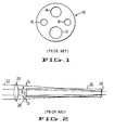
- a common delivery element is an endoscope 10 which is illustrated in cross section in Figure 1.
- the endoscope in Figure 1 is of the type that might be used in a laparoscopy and is often referred to as a laparoscope.
- the laparoscope body will typically have a number of axially extending bores 12, 14, 16 and 18.
- the laser beam may be directed through bore 12.
- Bore 14 may be used for optical feedback so the surgeon can view the tissue site.
- the two smaller bores 16 and 18 can be used to deliver illumination via fiber optic bundles to the treatment site.
- a coupler is used to join the end of the articulated arm to the entrance of the endoscope.
- a number of medical device companies manufacture and sell endoscopes each of which have slightly different entrance end configurations.
- a coupler with a complimentary mating design for each different endoscope design, there exists a coupler with a complimentary mating design.
- the coupler is typically provided with a conically shaped male mating end which is received in a conically shaped female mating configuration formed at the entrance of the endoscope.
- the mating conical configurations allow the two pieces to be adjusted when mounted. The alignment of the system relies heavily on the accuracy of the mating cones.
- the latter mounting approach has been less than satisfactory. More particularly, the prior approach required the doctor to adjust and test the alignment of the beam each time a new endoscope was attached. Since a new sterile endoscope is used for each new surgical procedure, the doctor must repeatedly adjust the alignment of the system. More significantly, even if the doctor is able to initially align the beam, the continuous movement of the articulated arm during the surgical procedure often results in the alignment being lost. If the alignment is lost, the percentage of the beam power transmitted down the endoscope is adversely affected. Moreover, misalignment of the components affects beam shape and size. Accordingly, it would be desirable to provide an improved coupler which could provide accurate and stable alignment of the mating components.
- Figure 2 illustrates the problem.
- the focal power of the lens 20 is selected to bring the focus of the beam 22 near the end 24 of the endoscope 26
- the diameter D1 of the beam at the entrance 28 will be significantly larger than the diameter D2 of the endoscope bore. This disparity results in severe clipping of the beam at the entrance reducing the power injected into the endoscope.
- the subject invention provides for a coupler for use in a medical laser system.
- the laser system is of the type that includes a laser for generating a beam of radiation.
- a delivery system is connected to the laser for delivering the beam to the treatment site.
- the delivery system includes an articulated arm and an endoscope.
- a coupler is provided for connecting the arm to the endoscope.
- the coupler is provided with an axially projecting tube which is receivable in the bore of the endoscope.
- the tube allows the position of the coupler to be registered with respect to the inner surface of the bore.
- the tube extends substantially the length of the bore.
- the tube is shorter and is provided with an adjustment feature to facilitate use with bores of slightly different diameters.
- an elastomeric ring is interposed between the coupler and the end of the endoscope so that registration is independent of the accuracy of the fabrication of the entrance configuration of the endoscope and relies entirely on the interaction between the tube and inner surface of the bore.
- an improved focusing mechanism is provided. More specifically, a two element telescope is provided. The focal powers and positions of the elements are selected so that the diameter of the beam at the entrance of the endoscope is less than the diameter of the bore. In addition, the focal plane of the beam is located just beyond the distal end of the endoscope.
- Figure 1 is a cross sectional view of a conventional endoscope found in the prior art.
- Figure 2 is a schematic illustration of a coupler lens and an endoscope found in the prior art.
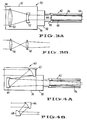
- Figure 3a is a schematic illustration of a coupler formed in accordance with the subject invention shown in conjunction with an endoscope.
- Figure 3b is a schematic illustration of an alternate lens pair for use in the coupler shown in Figure 3a.
- Figure 4a is a schematic illustration of an alternate embodiment of a coupler formed in accordance with the subject invention shown in conjunction with an endoscope.
- Figure 4b is a schematic illustration of an alternate mirror pair for use in the coupler shown in Figure 4a.
- Figure 5 is a cross sectional view of a third embodiment of a coupler formed in accordance with the subject invention shown in conjunction with an endoscope.
- Figure 6 is an exploded perspective view of the adapter flange of the coupler illustrated in Figure 5.
- Figure 7 is a schematic illustration of the mating end of the subject coupler for use with an endoscope having a conical female mating end.
- Figure 8 is a schematic illustration of the mating end of the subject coupler for use with an endoscope having a conical male mating end.
- Figure 9 is a schematic illustration of an alternate embodiment of the coupler of the subject invention shown with an endoscope having a conical female end.
- Figure 10 is a perspective view of the coupler shown in Figure 9.
- Coupler 30 includes a body 32, one end 34 of which is connectable to an articulated arm (not shown).
- the opposed end 36 includes an adapter flange 38.
- Adapter flange 38 is configured to mate with the entrance end 40 of endoscope 42.
- the configuration of the distal end 44 of the flange 38 and the use of coupling nuts (if required) is dictated by the endoscope manufacturer and will be discussed in more detail below with respect to Figures 7 and 8.
- the distal end 44 of flange 38 is additionally provided with an axially projecting tube 46.
- Tube 46 is receivable in the bore 48 of the endoscope 40.
- tube 46 extends substantially the length of the endoscope.
- the outer diameter of the tube is configured to be slightly less than the inner diameter of the endoscope.
- the minimum clearance should be about .001 inches so that the tube 46 can be easily slid into the bore.
- tube 46 results in the alignment of the coupler being registered exactly with the inner surface of the bore of the endoscope. By this arrangement, no adjustment is necessary when the endoscope is mounted to the coupler. In addition, the alignment will be maintained throughout the procedure.
- Figure 3a also illustrates the new focusing system of the subject coupler.
- the focusing system includes a first positive lens 50 for focusing the incoming laser beam.
- a second, negative lens 52 is provided downstream from the positive lens.
- the lens pair functions as a telescope to place the focus of the beam just beyond the distal end 54 of the endoscope. More significantly, the lens pair also adjusts the diameter of the beam at the entrance to the endoscope. In the preferred embodiment, the diameter of the beam at the endoscope entrance is less than the diameter of the bore so that clipping of the beam is avoided even where the diameter of the bore is quite small.
- the position of the lens pair can be fixed within the coupler.
- a means could be provided for adjusting the spacing between the lens pair so that spot size at the end of the endoscope could be varied.
- Figure 3b illustrates an alternative lens pair that is optically equivalent to the pair shown in Figure 3a.
- both of the lenses 56 and 58 are positive elements.
- Figures 4a and 4b illustrate alternate embodiments of the subject coupler 60.
- the focusing elements are defined by curved mirrors.
- both of the mirrors 62 and 64 are positive elements.
- the first mirror 66 is a positive element and the second mirror 68 is a negative element.
- Figure 5 is cross sectional view of a coupler 70 formed in accordance with the subject invention that has been fabricated and tested.
- the main body 72 of the coupler is configured to house and support the positive and negative lenses 74 and 76.
- Each lens is mounted in a lens cell 78 and 80.
- Each lens is mounted by inserting the associated lens cell into the body 72.
- Set screws 82 are used to lock the cells in place and permit some lateral alignment of the lenses.
- Both of the lenses 74 and 76 are formed from zinc selenide which is transmissive to both visible and CO2 radiation.
- the first lens 74 is provided with a focal length of 75mm.
- the second lens is provided with a focal length of -50mm and is spaced from the positive lens a distance of 30mm.
- the negative lens is also spaced from the entrance end of the endoscope 94 by 50mm.
- the endoscope 94 is 350mm long.
- the diameter of the incoming beam from the articulated arm is on the order of 8mm. This diameter is reduced to about 4.8mm in the plane of lens 76.
- the diameter of the beam at the entrance to the endoscope is on the order of 4.28mm which is significantly less than the 5mm of the bore 96.
- the lens system will create a focal plane at the distal end of the endoscope approximately 350mm away from the negative lens 76.
- the diameter of the beam at this location will be approximately 1.5mm.
- Figures 5 and 6 illustrate an alternative form for the flange 102 and alignment tube 104.
- tube 104 extends only a short distance, approximately 50mm, down the length of the 350mm bore of the endoscope. This configuration should be easier to fabricate and assemble. This configuration is also designed to be used with a variety of slightly different size bores.
- the end of the tube 104 is provided with a radially projecting annulus 106.
- the diameter of the annulus 106 can be slightly larger than the inner diameter of the bore 96 of the endoscope.
- the annulus 106 is provided with a plurality of axially extending slots 108. Each slot 108 is about 0.200 inches long and 0.025 inches wide. The slots 108 allow for some compression of the tube into bores-of slightly smaller diameter. This compression fit should enhance stability and help maintain alignment.
- a coupler nut 110 is provided to connect the flange 102 to the body 72.
- Figure 7 and 8 are two alternate configurations for the mating end of the subject coupler designed to interface with the mating ends of existing endoscopes.
- the mating configurations were typically conical.
- the accuracy of these assemblies was dependent on the accuracy of the cones.
- Figure 7 illustrates an endoscope 120 having a female mating cone 122.
- the mating end 124 of the flange of the subject coupler is provided with a spherical surface that centers itself in the female cone 122 independent of the accuracy of the angle of the female cone. Angular alignment of the coupler is then guaranteed by the axially extending tube 126 which projects into and registers with the bore 128 of the endoscope.
- Figure 8 illustrates an endoscope 130 having a male mating cone 132.
- the mating end 134 of the subject coupler is provided with a torroidal surface.
- the torroidal surface centers on the male cone with alignment being provided by the axially extending tube 136.
- the embodiment shown in Figure 9 is designed to overcome the latter problem.
- the flange 140 is not rigidly connected to the entrance 142 of the endoscope 144.
- an elastomeric ring member 146 is inserted between the flange and the entrance 142.
- the ring 146 provides a seat and seal for the coupler while allowing the angle of the coupler to vary with respect to the endoscope bore. In this manner, the alignment of the coupler is not dependent on the accuracy of the construction of the entrance end configuration of the endoscope.
- the alignment of the coupler is based solely on the interface between the alignment tube 148 and the inner surface of the endoscope.
- the alignment tube is provided with a pair of axially spaced annuli 150 and 152. These annuli are similar in function and structure to the annulus 106 illustrated in Figures 5 and 6.
- the second annulus 150 provides the extra kinematic support necessary in this configuration where the flange is floating with respect to the entrance of the endoscope. If annuli are not desired, it would be sufficient to extend the length of the alignment tube down a greater portion of the endoscope bore as shown in Figures 3 and 4.
- Figure 10 is a perspective view of a coupler which has been fabricated and tested.
- the annulus 152 is provided with a plurality of axially extending slots 158 running from the end of the tube 148 a distance of about 0.30 inches.
- a second set of slots 160 extend through the second annulus 150 and along the tube on either side of the annulus.
- the total length of slots 160 is on the order of 0.80 inches.
- the alignment tube 148 is 2.135 inches in length.
- the elastomeric member 146 would be located at the end of the flange as shown in phantom line in Figure 10.
- a suitable elastomeric member would be a rubber ring having a cross sectional diameter of 0.3 to 0.4 inches and formed from silicone rubber.
- a purge gas is typically supplied to the treatment site through a fitting on the side of the endoscope (not shown). Hole 162 is provided in tube 148 to facilitate the flow of the purge gas.
- an elastomeric member as an interface between the flange and the endoscope can be extended to mating configurations other than the one shown in Figure 9.
- the ring could be used where the entrance end of the endoscope has a male conical configuration as shown in Figure 8.
- a ring and flange structure could also be designed for use with the planar mating surface shown in Figure 5.
- the coupler includes an axially extending tube receivable in the bore of an endoscope to improve alignment.
- a telescope optical system is disclosed for reducing the clipping of the beam at the entrance to the endoscope.
Landscapes
- Physics & Mathematics (AREA)
- Optics & Photonics (AREA)
- Engineering & Computer Science (AREA)
- Plasma & Fusion (AREA)
- Mechanical Engineering (AREA)
- Health & Medical Sciences (AREA)
- General Physics & Mathematics (AREA)
- Surgery (AREA)
- Life Sciences & Earth Sciences (AREA)
- Medical Informatics (AREA)
- Animal Behavior & Ethology (AREA)
- Otolaryngology (AREA)
- Biomedical Technology (AREA)
- Heart & Thoracic Surgery (AREA)
- Nuclear Medicine, Radiotherapy & Molecular Imaging (AREA)
- Molecular Biology (AREA)
- Electromagnetism (AREA)
- General Health & Medical Sciences (AREA)
- Public Health (AREA)
- Veterinary Medicine (AREA)
- Endoscopes (AREA)
- Optical Couplings Of Light Guides (AREA)
- Laser Surgery Devices (AREA)
Applications Claiming Priority (4)
| Application Number | Priority Date | Filing Date | Title |
|---|---|---|---|
| US69424591A | 1991-05-01 | 1991-05-01 | |
| US694245 | 1991-05-01 | ||
| US07/737,395 US5136676A (en) | 1991-05-01 | 1991-07-29 | Coupler for a laser delivery system |
| US737395 | 1991-07-29 |
Publications (3)
| Publication Number | Publication Date |
|---|---|
| EP0511805A2 true EP0511805A2 (fr) | 1992-11-04 |
| EP0511805A3 EP0511805A3 (en) | 1993-06-23 |
| EP0511805B1 EP0511805B1 (fr) | 1997-07-02 |
Family
ID=27105336
Family Applications (1)
| Application Number | Title | Priority Date | Filing Date |
|---|---|---|---|
| EP92303767A Expired - Lifetime EP0511805B1 (fr) | 1991-05-01 | 1992-04-27 | Coupleur pour un système de transmission d'un faisceau laser |
Country Status (4)
| Country | Link |
|---|---|
| EP (1) | EP0511805B1 (fr) |
| JP (1) | JPH05181085A (fr) |
| DE (1) | DE69220614T2 (fr) |
| IL (1) | IL101471A (fr) |
Cited By (8)
| Publication number | Priority date | Publication date | Assignee | Title |
|---|---|---|---|---|
| WO1995019147A1 (fr) * | 1994-01-14 | 1995-07-20 | Coherent, Inc. | Piece a main utilisee pour generer un faisceau laser tres concentre utilise dans des interventions dermatologiques |
| FR2737814A1 (fr) * | 1995-08-11 | 1997-02-14 | Soc D Production Et De Rech Ap | Procede et dispositif de commande d'une source laser a plusieurs modules laser pour optimiser le traitement de surface par laser |
| FR2737786A1 (fr) * | 1995-08-11 | 1997-02-14 | Soc D Production Et De Rech Ap | Dispositif optique pour homogeneiser un faisceau laser |
| WO2002076290A1 (fr) * | 2001-03-21 | 2002-10-03 | Visionscope, Inc. | Systeme d'endoscope miniature |
| EP1417520A4 (fr) * | 2001-02-09 | 2005-03-23 | Sanmina Sci Corp | SYSTEME D'ALIGNEMENT POUR UN CABLE à FIBRE OPTIQUE |
| US6963678B2 (en) | 2001-02-09 | 2005-11-08 | Sanmina-Sci Corporation | Electro-optical transducer with multi-reflector beam-expanding and collimating input/output device |
| WO2010118197A1 (fr) * | 2009-04-10 | 2010-10-14 | Raytheon Company | Dispositif et procédé de couplage laser à fibre optique |
| CN112433308A (zh) * | 2020-12-07 | 2021-03-02 | 中山新诺科技股份有限公司 | 一种高功率激光光束的光纤耦合调节装置 |
Families Citing this family (1)
| Publication number | Priority date | Publication date | Assignee | Title |
|---|---|---|---|---|
| US8317689B1 (en) | 1999-09-13 | 2012-11-27 | Visionscope Technologies Llc | Miniature endoscope system |
Family Cites Families (9)
| Publication number | Priority date | Publication date | Assignee | Title |
|---|---|---|---|---|
| DE2059821A1 (de) * | 1970-12-04 | 1972-06-22 | Kutter Anton Dipl Ing | Spiegelteleskop in Schiefspiegleranordnung |
| US3982541A (en) * | 1974-07-29 | 1976-09-28 | Esperance Jr Francis A L | Eye surgical instrument |
| US4144888A (en) * | 1976-09-15 | 1979-03-20 | Malyshev Boris N | Device for treatment by laser emission |
| US4122853A (en) * | 1977-03-14 | 1978-10-31 | Spectra-Med | Infrared laser photocautery device |
| DE2803898A1 (de) * | 1978-01-30 | 1979-08-02 | Sigma Instr Gmbh | Laser-endoskop |
| US4658817A (en) * | 1985-04-01 | 1987-04-21 | Children's Hospital Medical Center | Method and apparatus for transmyocardial revascularization using a laser |
| DE3800555A1 (de) * | 1988-01-12 | 1989-07-27 | Ulrich Dardenne Stiftung Ev | Vorrichtung zur ablativen photodekomposition von zahnhartsubstanzen mittels eines eine wellenlaenge von 193 nm emittierenden argon/fluorid-excimer-lasers und einer applikationsvorrichtung fuer dieses laserlicht, sowie verwendung dieser vorrichtung zur zahnbehandlung |
| DE351240T1 (de) * | 1988-07-14 | 1991-09-26 | Advanced Interventional Systems, Inc., Costa Mesa, Calif. | Leitungs- und ausstrahlungssystem fuer hochenergie-pulsierendes laser-licht. |
| IT1233147B (it) * | 1989-02-09 | 1992-03-14 | El En S R L | Dispositivo per l'allineamento di un fascio laser all'interno di un braccio tubolare articolato |
-
1992
- 1992-04-02 IL IL10147192A patent/IL101471A/en not_active IP Right Cessation
- 1992-04-27 DE DE69220614T patent/DE69220614T2/de not_active Expired - Fee Related
- 1992-04-27 EP EP92303767A patent/EP0511805B1/fr not_active Expired - Lifetime
- 1992-04-30 JP JP4137952A patent/JPH05181085A/ja active Pending
Cited By (11)
| Publication number | Priority date | Publication date | Assignee | Title |
|---|---|---|---|---|
| WO1995019147A1 (fr) * | 1994-01-14 | 1995-07-20 | Coherent, Inc. | Piece a main utilisee pour generer un faisceau laser tres concentre utilise dans des interventions dermatologiques |
| US5558666A (en) * | 1994-01-14 | 1996-09-24 | Coherent, Inc. | Handpiece for producing highly collimated laser beam for dermatological procedures |
| FR2737814A1 (fr) * | 1995-08-11 | 1997-02-14 | Soc D Production Et De Rech Ap | Procede et dispositif de commande d'une source laser a plusieurs modules laser pour optimiser le traitement de surface par laser |
| FR2737786A1 (fr) * | 1995-08-11 | 1997-02-14 | Soc D Production Et De Rech Ap | Dispositif optique pour homogeneiser un faisceau laser |
| WO1997007578A1 (fr) * | 1995-08-11 | 1997-02-27 | Societe De Production Et De Recherches Appliquees | Dispositif de commande d'une source laser a plusieurs modules laser pour optimiser energetiquement et spatialement le traitement de surface par laser |
| US6014401A (en) * | 1995-08-11 | 2000-01-11 | Societe De Production Et De Recherches Appliquees | Device for controlling a laser source with multiple laser units for the energy and spatial optimization of a laser surface treatment |
| EP1417520A4 (fr) * | 2001-02-09 | 2005-03-23 | Sanmina Sci Corp | SYSTEME D'ALIGNEMENT POUR UN CABLE à FIBRE OPTIQUE |
| US6963678B2 (en) | 2001-02-09 | 2005-11-08 | Sanmina-Sci Corporation | Electro-optical transducer with multi-reflector beam-expanding and collimating input/output device |
| WO2002076290A1 (fr) * | 2001-03-21 | 2002-10-03 | Visionscope, Inc. | Systeme d'endoscope miniature |
| WO2010118197A1 (fr) * | 2009-04-10 | 2010-10-14 | Raytheon Company | Dispositif et procédé de couplage laser à fibre optique |
| CN112433308A (zh) * | 2020-12-07 | 2021-03-02 | 中山新诺科技股份有限公司 | 一种高功率激光光束的光纤耦合调节装置 |
Also Published As
| Publication number | Publication date |
|---|---|
| DE69220614D1 (de) | 1997-08-07 |
| DE69220614T2 (de) | 1998-01-08 |
| IL101471A0 (en) | 1992-12-30 |
| EP0511805A3 (en) | 1993-06-23 |
| JPH05181085A (ja) | 1993-07-23 |
| IL101471A (en) | 1995-03-30 |
| EP0511805B1 (fr) | 1997-07-02 |
Similar Documents
| Publication | Publication Date | Title |
|---|---|---|
| US5136676A (en) | Coupler for a laser delivery system | |
| EP1315443B1 (fr) | Arthroscope a visions variables | |
| US6513962B1 (en) | Illumination system adapted for surgical lighting | |
| US5430620A (en) | Compact surgical illumination system capable of dynamically adjusting the resulting field of illumination | |
| US5289557A (en) | Optics for medical laser | |
| EP0336045A1 (fr) | Dispositif pour transporter un faisceau laser pour un système médical à laser | |
| GB2076993A (en) | Optical fibre light guides for use with laser | |
| WO2005040863A2 (fr) | Appareil et procede de diffusion de l'energie laser errant par defaut de couplage dans des fibres de petite ame | |
| EP0511805A2 (fr) | Coupleur pour un système de transmission d'un faisceau laser | |
| US5800343A (en) | Endoscope light guide connector allowing adjustment of the angle of incident light rays | |
| US9782063B2 (en) | Optical coupling efficiency detection assembly and method of assembling the same | |
| US5852694A (en) | High power fiber optic connector | |
| US6512868B1 (en) | Precision fiber optic collimator | |
| US5243399A (en) | Alignment tool for endoscopes | |
| US20240019657A1 (en) | Alignment method and tools | |
| US5251612A (en) | Self-aligning coupler for a laser endoscope | |
| US4856512A (en) | Laser head and microscope attachment assembly with swivel capability | |
| EP0392718B1 (fr) | Connecteur optique pour endoscope | |
| GB2199960A (en) | Flexible delivery system | |
| RU2040217C1 (ru) | Манипулятор лазерного хирургического аппарата | |
| JP2021511843A (ja) | 口腔レーザー治療装置のハンドルに用いられる光路切換構造 | |
| JP2001269312A (ja) | 内視鏡装置 | |
| JPS63311314A (ja) | 光結合器 | |
| IL100441A (en) | Coupler device for laser apparatus | |
| JPH0468944B2 (fr) |
Legal Events
| Date | Code | Title | Description |
|---|---|---|---|
| PUAI | Public reference made under article 153(3) epc to a published international application that has entered the european phase |
Free format text: ORIGINAL CODE: 0009012 |
|
| AK | Designated contracting states |
Kind code of ref document: A2 Designated state(s): CH DE FR GB IT LI |
|
| PUAL | Search report despatched |
Free format text: ORIGINAL CODE: 0009013 |
|
| AK | Designated contracting states |
Kind code of ref document: A3 Designated state(s): CH DE FR GB IT LI |
|
| 17P | Request for examination filed |
Effective date: 19931216 |
|
| 17Q | First examination report despatched |
Effective date: 19950512 |
|
| GRAG | Despatch of communication of intention to grant |
Free format text: ORIGINAL CODE: EPIDOS AGRA |
|
| GRAH | Despatch of communication of intention to grant a patent |
Free format text: ORIGINAL CODE: EPIDOS IGRA |
|
| GRAH | Despatch of communication of intention to grant a patent |
Free format text: ORIGINAL CODE: EPIDOS IGRA |
|
| RAP1 | Party data changed (applicant data changed or rights of an application transferred) |
Owner name: COHERENT, INC. |
|
| RIN1 | Information on inventor provided before grant (corrected) |
Inventor name: KOOP, DALE Inventor name: TROST, DAVID Inventor name: ARNETT, MICHAEL |
|
| GRAA | (expected) grant |
Free format text: ORIGINAL CODE: 0009210 |
|
| AK | Designated contracting states |
Kind code of ref document: B1 Designated state(s): CH DE FR GB IT LI |
|
| PG25 | Lapsed in a contracting state [announced via postgrant information from national office to epo] |
Ref country code: IT Free format text: LAPSE BECAUSE OF FAILURE TO SUBMIT A TRANSLATION OF THE DESCRIPTION OR TO PAY THE FEE WITHIN THE PRESCRIBED TIME-LIMIT;WARNING: LAPSES OF ITALIAN PATENTS WITH EFFECTIVE DATE BEFORE 2007 MAY HAVE OCCURRED AT ANY TIME BEFORE 2007. THE CORRECT EFFECTIVE DATE MAY BE DIFFERENT FROM THE ONE RECORDED. Effective date: 19970702 Ref country code: FR Free format text: THE PATENT HAS BEEN ANNULLED BY A DECISION OF A NATIONAL AUTHORITY Effective date: 19970702 |
|
| REG | Reference to a national code |
Ref country code: CH Ref legal event code: EP |
|
| REF | Corresponds to: |
Ref document number: 69220614 Country of ref document: DE Date of ref document: 19970807 |
|
| ET | Fr: translation filed | ||
| REG | Reference to a national code |
Ref country code: CH Ref legal event code: NV Representative=s name: BOVARD AG PATENTANWAELTE |
|
| PG25 | Lapsed in a contracting state [announced via postgrant information from national office to epo] |
Ref country code: GB Free format text: LAPSE BECAUSE OF NON-PAYMENT OF DUE FEES Effective date: 19980427 |
|
| PG25 | Lapsed in a contracting state [announced via postgrant information from national office to epo] |
Ref country code: CH Free format text: LAPSE BECAUSE OF NON-PAYMENT OF DUE FEES Effective date: 19980430 Ref country code: LI Free format text: LAPSE BECAUSE OF NON-PAYMENT OF DUE FEES Effective date: 19980430 |
|
| PLBE | No opposition filed within time limit |
Free format text: ORIGINAL CODE: 0009261 |
|
| STAA | Information on the status of an ep patent application or granted ep patent |
Free format text: STATUS: NO OPPOSITION FILED WITHIN TIME LIMIT |
|
| 26N | No opposition filed | ||
| REG | Reference to a national code |
Ref country code: CH Ref legal event code: PL |
|
| GBPC | Gb: european patent ceased through non-payment of renewal fee |
Effective date: 19980427 |
|
| PG25 | Lapsed in a contracting state [announced via postgrant information from national office to epo] |
Ref country code: DE Free format text: LAPSE BECAUSE OF NON-PAYMENT OF DUE FEES Effective date: 19990202 |
|
| REG | Reference to a national code |
Ref country code: FR Ref legal event code: ST |