EP0512216A2 - Véhicule avec essieu auto-pivotable rétractable - Google Patents
Véhicule avec essieu auto-pivotable rétractable Download PDFInfo
- Publication number
- EP0512216A2 EP0512216A2 EP92103932A EP92103932A EP0512216A2 EP 0512216 A2 EP0512216 A2 EP 0512216A2 EP 92103932 A EP92103932 A EP 92103932A EP 92103932 A EP92103932 A EP 92103932A EP 0512216 A2 EP0512216 A2 EP 0512216A2
- Authority
- EP
- European Patent Office
- Prior art keywords
- axle
- vehicle according
- wheels
- valve
- trailing axle
- Prior art date
- Legal status (The legal status is an assumption and is not a legal conclusion. Google has not performed a legal analysis and makes no representation as to the accuracy of the status listed.)
- Granted
Links
- 230000003028 elevating effect Effects 0.000 title 1
- 230000000903 blocking effect Effects 0.000 description 2
- 230000001419 dependent effect Effects 0.000 description 1
- 238000011161 development Methods 0.000 description 1
- 230000018109 developmental process Effects 0.000 description 1
- 238000009987 spinning Methods 0.000 description 1
- 238000009423 ventilation Methods 0.000 description 1
Images
Classifications
-
- B—PERFORMING OPERATIONS; TRANSPORTING
- B60—VEHICLES IN GENERAL
- B60T—VEHICLE BRAKE CONTROL SYSTEMS OR PARTS THEREOF; BRAKE CONTROL SYSTEMS OR PARTS THEREOF, IN GENERAL; ARRANGEMENT OF BRAKING ELEMENTS ON VEHICLES IN GENERAL; PORTABLE DEVICES FOR PREVENTING UNWANTED MOVEMENT OF VEHICLES; VEHICLE MODIFICATIONS TO FACILITATE COOLING OF BRAKES
- B60T8/00—Arrangements for adjusting wheel-braking force to meet varying vehicular or ground-surface conditions, e.g. limiting or varying distribution of braking force
- B60T8/32—Arrangements for adjusting wheel-braking force to meet varying vehicular or ground-surface conditions, e.g. limiting or varying distribution of braking force responsive to a speed condition, e.g. acceleration or deceleration
- B60T8/321—Arrangements for adjusting wheel-braking force to meet varying vehicular or ground-surface conditions, e.g. limiting or varying distribution of braking force responsive to a speed condition, e.g. acceleration or deceleration deceleration
- B60T8/3255—Systems in which the braking action is dependent on brake pedal data
- B60T8/327—Pneumatic systems
-
- B—PERFORMING OPERATIONS; TRANSPORTING
- B60—VEHICLES IN GENERAL
- B60T—VEHICLE BRAKE CONTROL SYSTEMS OR PARTS THEREOF; BRAKE CONTROL SYSTEMS OR PARTS THEREOF, IN GENERAL; ARRANGEMENT OF BRAKING ELEMENTS ON VEHICLES IN GENERAL; PORTABLE DEVICES FOR PREVENTING UNWANTED MOVEMENT OF VEHICLES; VEHICLE MODIFICATIONS TO FACILITATE COOLING OF BRAKES
- B60T8/00—Arrangements for adjusting wheel-braking force to meet varying vehicular or ground-surface conditions, e.g. limiting or varying distribution of braking force
- B60T8/26—Arrangements for adjusting wheel-braking force to meet varying vehicular or ground-surface conditions, e.g. limiting or varying distribution of braking force characterised by producing differential braking between front and rear wheels
- B60T8/266—Arrangements for adjusting wheel-braking force to meet varying vehicular or ground-surface conditions, e.g. limiting or varying distribution of braking force characterised by producing differential braking between front and rear wheels using valves or actuators with external control means
-
- B—PERFORMING OPERATIONS; TRANSPORTING
- B60—VEHICLES IN GENERAL
- B60T—VEHICLE BRAKE CONTROL SYSTEMS OR PARTS THEREOF; BRAKE CONTROL SYSTEMS OR PARTS THEREOF, IN GENERAL; ARRANGEMENT OF BRAKING ELEMENTS ON VEHICLES IN GENERAL; PORTABLE DEVICES FOR PREVENTING UNWANTED MOVEMENT OF VEHICLES; VEHICLE MODIFICATIONS TO FACILITATE COOLING OF BRAKES
- B60T8/00—Arrangements for adjusting wheel-braking force to meet varying vehicular or ground-surface conditions, e.g. limiting or varying distribution of braking force
- B60T8/32—Arrangements for adjusting wheel-braking force to meet varying vehicular or ground-surface conditions, e.g. limiting or varying distribution of braking force responsive to a speed condition, e.g. acceleration or deceleration
- B60T8/34—Arrangements for adjusting wheel-braking force to meet varying vehicular or ground-surface conditions, e.g. limiting or varying distribution of braking force responsive to a speed condition, e.g. acceleration or deceleration having a fluid pressure regulator responsive to a speed condition
- B60T8/349—Systems adapted to control a set of axles, e.g. tandem axles
-
- B—PERFORMING OPERATIONS; TRANSPORTING
- B60—VEHICLES IN GENERAL
- B60T—VEHICLE BRAKE CONTROL SYSTEMS OR PARTS THEREOF; BRAKE CONTROL SYSTEMS OR PARTS THEREOF, IN GENERAL; ARRANGEMENT OF BRAKING ELEMENTS ON VEHICLES IN GENERAL; PORTABLE DEVICES FOR PREVENTING UNWANTED MOVEMENT OF VEHICLES; VEHICLE MODIFICATIONS TO FACILITATE COOLING OF BRAKES
- B60T8/00—Arrangements for adjusting wheel-braking force to meet varying vehicular or ground-surface conditions, e.g. limiting or varying distribution of braking force
- B60T8/32—Arrangements for adjusting wheel-braking force to meet varying vehicular or ground-surface conditions, e.g. limiting or varying distribution of braking force responsive to a speed condition, e.g. acceleration or deceleration
- B60T8/34—Arrangements for adjusting wheel-braking force to meet varying vehicular or ground-surface conditions, e.g. limiting or varying distribution of braking force responsive to a speed condition, e.g. acceleration or deceleration having a fluid pressure regulator responsive to a speed condition
- B60T8/48—Arrangements for adjusting wheel-braking force to meet varying vehicular or ground-surface conditions, e.g. limiting or varying distribution of braking force responsive to a speed condition, e.g. acceleration or deceleration having a fluid pressure regulator responsive to a speed condition connecting the brake actuator to an alternative or additional source of fluid pressure, e.g. traction control systems
- B60T8/4809—Traction control, stability control, using both the wheel brakes and other automatic braking systems
- B60T8/4818—Traction control, stability control, using both the wheel brakes and other automatic braking systems in pneumatic brake systems
-
- Y—GENERAL TAGGING OF NEW TECHNOLOGICAL DEVELOPMENTS; GENERAL TAGGING OF CROSS-SECTIONAL TECHNOLOGIES SPANNING OVER SEVERAL SECTIONS OF THE IPC; TECHNICAL SUBJECTS COVERED BY FORMER USPC CROSS-REFERENCE ART COLLECTIONS [XRACs] AND DIGESTS
- Y10—TECHNICAL SUBJECTS COVERED BY FORMER USPC
- Y10S—TECHNICAL SUBJECTS COVERED BY FORMER USPC CROSS-REFERENCE ART COLLECTIONS [XRACs] AND DIGESTS
- Y10S303/00—Fluid-pressure and analogous brake systems
- Y10S303/09—Plural processors
Definitions
- the invention relates to a vehicle with a lifting trailing axle according to the preamble of patent claim 1.
- a vehicle of the type mentioned is known from DE-PS 31 01 731.
- a pneumatic brake system in which a vehicle with a sensed drive axle, ie. H. the drive wheels are equipped with speed sensors, and with a non-sensed trailing axle, the brake cylinders of the trailing axle are attached to the brake cylinders of the drive axle in terms of pressure. While an anti-lock control system is running, the wheels of the trailing axle are also controlled by the drive wheels.
- the invention has for its object to ensure an approximately uniform wear of all brake pads in a vehicle with a lifting trailing axle.
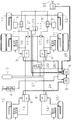
- FIG. 1 shows a simplified, schematic representation of the pneumatic and electronic part of a vehicle with an anti-lock braking system (ABS), traction control system (ASR) and a lifting trailing axle.
- ABS anti-lock braking system
- ASR traction control system
- the vehicle has three axles, the front axle with (1), the drive axle with (2) and the liftable trailing axle with (3).
- Spring brake cylinders (14, 14 ') are assigned to the wheels of the front axle (1). These are connected to so-called modulators (8, 8 ').
- the modulators are connected to a compressed air supply (13).
- the speed of the wheels of the front axle (1) is sensed by means of speed sensors (10, 10 ').
- the modulators (8, 8 ') contain an E / P converter, which can pneumatically simulate an electrically specified brake pressure.
- the modulators (8, 8 ') also contain an electronic part.
- the speed sensors (10, 10 ') are attached to these connected.
- the modulators (8, 8 ') are connected via a data line (24) to an electronic central unit (ZE) (5) which is responsible for the front axle (1).
- ZE electronic central unit
- a further central unit (6) which is responsible for controlling the drive axle (2).
- modulators (9, 9 ') is connected to modulators (9, 9 ') by a data line (25).
- a further central unit (7) is also connected to the central unit (6) via a further data line (26). This is mainly responsible for the control of a trailer, which can be connected via a connection (23).
- the central unit (6) is further connected to a proportional valve (19) via a data line (22) (see below).
- a brake value transmitter (4) is connected to both central units (5, 6). This is actuated by the driver and gives his braking command via a line (27) to the central units (5, 6) mentioned.
- Both the electronic parts of the modulators and the central units are equipped with one or more microcomputers. It is an electrical braking system with "distributed intelligence”.
- the modulators (9, 9 ') already mentioned are likewise fed from the compressed air supply (13). They are used to adjust the brake pressure in the brake cylinders (15, 15 ') of the wheels of the drive axle (2).
- the brake cylinders (15, 15 ') are also designed as a spring accumulator.
- the pneumatic connections for the spring-loaded part (parking brake) are not shown for the sake of simplicity.
- Speed sensors (11, 11 ') for the wheels of the drive axle are connected to the electronic part of the modulators (9, 9').
- the wheels of the trailing axle (3) are equipped with brake cylinders (16, 16 ') without a spring component. Their speed is sensed using additional speed sensors (12, 12 ').
- the speed sensors of the trailing axle are connected via a line (21) to the electronic part of the proportional valve (19) and are thus indirectly connected to the central units (5, 6, 7) via the data line (22).
- the brake cylinders (16, 16 ') of the trailing axle are connected to two-way valves (18, 18'). These valves allow the greater pressure to pass through to the brake cylinders.
- the right side of the valves (18, 18 ') are connected to the output of the proportional valve (19).
- the left side of the valves (18, 18 ') is connected to the output of a select low valve (17, 17'). These select low valves allow the lower pressure to pass through.
- the select low valves (17, 17) are connected to the outputs of the modulators (9, 9 '). On the other hand, there is a connection via a 3/2-way valve (20) to the compressed air supply (13).
- the driver's braking request is recorded by the brake value transmitter (4) and forwarded to the modulators (8, 8 ', 9, 9') via the electronics mentioned. These convert the specified electrical signal into a corresponding pressure value.
- the 3/2-way valve (20) In normal operation, i.e. without running traction control system, the 3/2-way valve (20) is in the open position (as shown). The result of this is that the select low valves (17, 17 ') allow the braking pressures of the modulators (9, 9') to pass to the trailing axle (3). However, the brakes of the trailing axle are simultaneously applied via the proportional valve (19) and the two-way valves (18, 18 '), namely with an approximately 20 to 30 percent higher pressure than the brake cylinders of the drive axle (2). The lower pressure of the modulators (9, 9 ') is shut off by the two-way valves (18, 18'). The higher pressure is communicated to the proportional valve (19) via the data line (22). The pressure is fed to the brake cylinders (16, 16 ') via the two-way valves (18, 18').
- proportional valve (19) can be designed mechanically for a lower frequency than the modulators (8, 9), since it does not have to be ABS-compatible.
- the pressure on the trailing axle can also be set higher, e.g. B. up to 50% overbraking.
- the proportional valve (19) is switched to ventilation via line (22).
- the two-way valves (18, 18 ') and the open select-low valves (17, 17') now also control the brake cylinders of the trailing axle (3) by means of the brake pressure for the brake cylinders of the drive axle (2).
- the brakes on the drive axle (2) and trailing axle (3) must be designed so that the drive axle shows a tendency to lock at the same brake pressures. This prevents the co-controlled trailing axle from blocking. So there is side-by-side control.
- the brake system shown naturally works in the same way if there is a leading axle instead of a trailing axle (3). It is also of no importance whether the braking system is designed as an electrical braking system (EBS) with decentralized intelligence, as shown here, or whether only a normal anti-lock braking system with an additional drive control function is provided.
- EBS electrical braking system
Landscapes
- Engineering & Computer Science (AREA)
- Transportation (AREA)
- Mechanical Engineering (AREA)
- Physics & Mathematics (AREA)
- Fluid Mechanics (AREA)
- Regulating Braking Force (AREA)
Applications Claiming Priority (2)
| Application Number | Priority Date | Filing Date | Title |
|---|---|---|---|
| DE4114861A DE4114861A1 (de) | 1991-05-07 | 1991-05-07 | Fahrzeug mit liftbarer nachlaufachse |
| DE4114861 | 1991-05-07 |
Publications (3)
| Publication Number | Publication Date |
|---|---|
| EP0512216A2 true EP0512216A2 (fr) | 1992-11-11 |
| EP0512216A3 EP0512216A3 (fr) | 1992-12-02 |
| EP0512216B1 EP0512216B1 (fr) | 1995-04-26 |
Family
ID=6431149
Family Applications (1)
| Application Number | Title | Priority Date | Filing Date |
|---|---|---|---|
| EP92103932A Expired - Lifetime EP0512216B1 (fr) | 1991-05-07 | 1992-03-07 | Véhicule avec essieu auto-pivotable rétractable |
Country Status (4)
| Country | Link |
|---|---|
| US (1) | US5211449A (fr) |
| EP (1) | EP0512216B1 (fr) |
| JP (1) | JP3116314B2 (fr) |
| DE (2) | DE4114861A1 (fr) |
Cited By (1)
| Publication number | Priority date | Publication date | Assignee | Title |
|---|---|---|---|---|
| EP0934859A1 (fr) * | 1998-02-05 | 1999-08-11 | DaimlerChrysler AG | Dispositif pour contrÔler la répartition de force de freinage pour véhicules avec trois ou plusieurs essieux |
Families Citing this family (23)
| Publication number | Priority date | Publication date | Assignee | Title |
|---|---|---|---|---|
| DE4114861A1 (de) | 1991-05-07 | 1992-11-12 | Wabco Westinghouse Fahrzeug | Fahrzeug mit liftbarer nachlaufachse |
| JPH0571072U (ja) * | 1992-03-03 | 1993-09-24 | 曙ブレーキ工業株式会社 | 多軸車両用トラクションコントロール装置 |
| JP3366915B2 (ja) * | 1992-08-27 | 2003-01-14 | 日本電子工業株式会社 | 車両のアンチロックブレーキ装置の制御システム |
| US5456526A (en) * | 1992-11-27 | 1995-10-10 | Akebono Brake Industry Co., Ltd. | ABS control for individual axles of a three axle vehicle |
| US5342119A (en) * | 1992-12-28 | 1994-08-30 | Eaton Corporation | Traction control system valve |
| DE4413170A1 (de) * | 1994-04-15 | 1995-03-30 | Daimler Benz Ag | Bremsanlage mit ABS- und ASR-Funktion für eine angetriebene und eine nichtangetriebene Achse |
| DE4438222B4 (de) * | 1994-10-26 | 2008-02-14 | Knorr-Bremse Systeme für Nutzfahrzeuge GmbH | Verfahren und Vorrichtung zur Steuerung bzw. Regelung der Bremsanlage eines Fahrzeugs |
| DE19912316B4 (de) | 1999-03-19 | 2005-08-25 | Daimlerchrysler Ag | Mehrachsaggregat mit mindestens drei Achsen |
| CA2382787C (fr) | 1999-08-24 | 2008-10-14 | Holland Neway International, Inc. | Suspension de vehicule et soupape de commande de hauteur connexe |
| GB2357324A (en) * | 1999-12-14 | 2001-06-20 | Svtech Ltd | Braking control of a vehicle additional axle |
| DE10038046B4 (de) * | 2000-08-02 | 2005-11-03 | Knorr-Bremse Systeme für Nutzfahrzeuge GmbH | Stabilisierungseinrichtung für Kraftfahrzeuge mit druckluftbetriebenen Bremseinrichtungen |
| IL159046A0 (en) * | 2001-05-25 | 2004-05-12 | Haldex Brake Corp | Trailing arm suspension and height control system with motorized valve therefor |
| US7204478B2 (en) * | 2002-08-07 | 2007-04-17 | Haldex Brake Corporation | Height control valve with universal mounting for a suspension system |
| USD499173S1 (en) | 2002-08-07 | 2004-11-30 | Haldex Brake Corporation | Valve with three mounting holes |
| DE102004043510B4 (de) * | 2004-09-09 | 2014-12-04 | Iveco Magirus Ag | ABS-Bremssystem für Lastkraftwagen |
| US20060119174A1 (en) * | 2004-12-06 | 2006-06-08 | Bendix Commercial Vehicle Systems Llc | Distributed antilock brake system |
| US20070046098A1 (en) * | 2005-08-31 | 2007-03-01 | Bendix Commercial Vehicle Systems Llc | Vehicle stability system diagnostic method |
| US10836232B2 (en) | 2007-04-12 | 2020-11-17 | Haldex Brake Products Corporation | Electronic height control system for a vehicle with multiple input signals |
| US20080252025A1 (en) * | 2007-04-12 | 2008-10-16 | Plath Victor A | Electronic height control system for a vehicle with multiple input signals |
| US8544964B2 (en) * | 2010-06-29 | 2013-10-01 | Deere & Company | Brake control system for dual mode vehicle |
| DE102011012270B4 (de) * | 2011-02-24 | 2012-12-27 | Knorr-Bremse Systeme für Nutzfahrzeuge GmbH | Antriebsschlupfgeregelte Bremsanlage eines Haltestellen anfahrenden Kraftfahrzeugs |
| JP2025501476A (ja) | 2021-12-16 | 2025-01-22 | ガティック エーアイ インコーポレイテッド | 自律エージェントにおける障害に対処するための方法およびシステム |
| US12409824B1 (en) * | 2024-12-20 | 2025-09-09 | Gatik Ai Inc. | Drive-by-wire vehicle architecture |
Family Cites Families (19)
| Publication number | Priority date | Publication date | Assignee | Title |
|---|---|---|---|---|
| DE2545593A1 (de) * | 1975-10-11 | 1977-04-14 | Wabco Westinghouse Gmbh | Blockierschutzregelsystem |
| DE2614180A1 (de) * | 1976-04-02 | 1977-10-20 | Bosch Gmbh Robert | Blockierschutz-anlage |
| DE2811999A1 (de) * | 1978-03-18 | 1979-09-27 | Bosch Gmbh Robert | Antiblockierregelsystem fuer fahrzeuge |
| DE3138834A1 (de) * | 1981-01-21 | 1983-04-14 | Wabco Westinghouse Fahrzeugbremsen GmbH, 3000 Hannover | Antiblockiersystem, insbesondere fuer ein mehrachs-fahrzeug |
| DE3101731A1 (de) * | 1981-01-21 | 1982-08-26 | Wabco Fahrzeugbremsen Gmbh, 3000 Hannover | Antiblockiersystem, insbesondere fuer ein mehrachs-fahrzeug |
| DE3209592A1 (de) * | 1982-03-17 | 1983-09-29 | Robert Bosch Gmbh, 7000 Stuttgart | Zweikreis-druckmittelbremsanlage |
| US4460220A (en) * | 1982-04-27 | 1984-07-17 | Wabco Fahrzeugbremsen Gmbh | Anti-skid brake control system for a multi-axle vehicle |
| DE3219140C2 (de) * | 1982-05-21 | 1995-03-16 | Bosch Gmbh Robert | Wagenzug-Bremsanlage |
| DE3400566A1 (de) * | 1984-01-10 | 1985-07-18 | Robert Bosch Gmbh, 7000 Stuttgart | Bremsanlage fuer fahrzeuge |
| DE3423508A1 (de) * | 1984-06-26 | 1986-01-02 | Knorr-Bremse GmbH, 8000 München | Blockierschutzeinrichtung fuer kraftfahrzeuge |
| DE3501179A1 (de) * | 1985-01-16 | 1986-07-17 | Wabco Westinghouse Fahrzeugbremsen GmbH, 3000 Hannover | Elektrische bremsanlage |
| DE3501381A1 (de) * | 1985-01-17 | 1986-07-17 | Robert Bosch Gmbh, 7000 Stuttgart | Blockierschutz-bremssystem |
| DE3526559A1 (de) * | 1985-07-25 | 1987-01-29 | Wabco Westinghouse Fahrzeug | Antiblockiersystem |
| DE3637420A1 (de) * | 1986-11-03 | 1988-05-05 | Bosch Gmbh Robert | Zweikreis-bremsanlage |
| DE3700716A1 (de) * | 1987-01-13 | 1988-07-21 | Wabco Westinghouse Fahrzeug | Fahrzeug mit antiblockiersystem und antriebsschlupfregelung |
| DE3733801A1 (de) * | 1987-09-21 | 1989-03-30 | Wabco Westinghouse Fahrzeug | Antiblockiersystem fuer fahrzeuge |
| US4863221A (en) * | 1988-08-18 | 1989-09-05 | Eaton Corporation | Tandem drive axle anti-lock brake system |
| DE3923955A1 (de) * | 1989-07-19 | 1991-01-31 | Lucas Ind Plc | Bremsvorrichtung fuer ein zweiachsiges fahrzeug |
| DE4114861A1 (de) | 1991-05-07 | 1992-11-12 | Wabco Westinghouse Fahrzeug | Fahrzeug mit liftbarer nachlaufachse |
-
1991
- 1991-05-07 DE DE4114861A patent/DE4114861A1/de not_active Withdrawn
-
1992
- 1992-03-07 EP EP92103932A patent/EP0512216B1/fr not_active Expired - Lifetime
- 1992-03-07 DE DE59202002T patent/DE59202002D1/de not_active Expired - Lifetime
- 1992-04-07 JP JP04129222A patent/JP3116314B2/ja not_active Expired - Fee Related
- 1992-04-22 US US07/872,092 patent/US5211449A/en not_active Expired - Lifetime
Cited By (1)
| Publication number | Priority date | Publication date | Assignee | Title |
|---|---|---|---|---|
| EP0934859A1 (fr) * | 1998-02-05 | 1999-08-11 | DaimlerChrysler AG | Dispositif pour contrÔler la répartition de force de freinage pour véhicules avec trois ou plusieurs essieux |
Also Published As
| Publication number | Publication date |
|---|---|
| DE4114861A1 (de) | 1992-11-12 |
| EP0512216B1 (fr) | 1995-04-26 |
| US5211449A (en) | 1993-05-18 |
| JP3116314B2 (ja) | 2000-12-11 |
| DE59202002D1 (de) | 1995-06-01 |
| JPH05147522A (ja) | 1993-06-15 |
| EP0512216A3 (fr) | 1992-12-02 |
Similar Documents
| Publication | Publication Date | Title |
|---|---|---|
| EP0512216B1 (fr) | Véhicule avec essieu auto-pivotable rétractable | |
| DE4227084B4 (de) | Druckregelmodul einer Druckluft-Fahrzeugbremsanlage | |
| DE4227083C2 (de) | Elektronisches Bremssystem, insbesondere für Straßenfahrzeuge | |
| EP1530529B1 (fr) | Module regulateur de pression pour un systeme de freinage pneumatique d'un vehicule | |
| DE19581733B4 (de) | Bremssteueranordnung für einen Fahrzeugverbund | |
| EP0187901A2 (fr) | Installation de freinage commandée électriquement pour véhicules | |
| EP0274610B1 (fr) | Véhicule avec système antiblocage et antipatinage | |
| EP0734334A1 (fr) | Systeme de freinage electropneumatique pour vehicules automobiles | |
| DE4214182C2 (de) | Bremsdrucksteuereinrichtung zur Bremsbelagverschleißoptimierung in einem Kraftfahrzeug | |
| DE10004086C2 (de) | Bremsanlage für Fahrzeuge, insbesondere Nutzfahrzeuge | |
| EP0742764A1 (fr) | Systeme de freinage hydraulique pour vehicule automobile, plus particulierement pour une voiture particuliere, avec dispositif d'antiblocage | |
| EP1060966A2 (fr) | Soupape de frein de remorque pour systèmes de freinage antiblocage de remorque | |
| EP1185447B1 (fr) | Systeme de freinage de vehicule a commande par fluide sous pression | |
| EP0345203B1 (fr) | Installation de freinage avec moyen de pression régulé électroniquement | |
| DE3101731C2 (fr) | ||
| DE3138834C2 (fr) | ||
| DE2723847A1 (de) | Ueberwachungseinrichtung fuer eine blockiergeschuetzte fahrzeugbremsanlage | |
| DE2545593A1 (de) | Blockierschutzregelsystem | |
| EP1612114B1 (fr) | Procédé pour le freinage d'un véhicule | |
| EP0002073A1 (fr) | Dispositif de commande pour un essieu relevable d'un véhicule utilitaire | |
| EP1069016B2 (fr) | Installation de freinage actionnée par moyen de pression | |
| DE19859737A1 (de) | Hydraulische Bremsanlage | |
| EP0487862B1 (fr) | Système antiblocage pour véhicules à traction sur les quatres roues | |
| DE102010020267B4 (de) | Druckmittelbestätigte Bremseinrichtung mit Niederdruck- und Hochdruckbereich | |
| WO1995025652A1 (fr) | Circuiterie pour un systeme de freinage a regulation electronique |
Legal Events
| Date | Code | Title | Description |
|---|---|---|---|
| PUAI | Public reference made under article 153(3) epc to a published international application that has entered the european phase |
Free format text: ORIGINAL CODE: 0009012 |
|
| PUAL | Search report despatched |
Free format text: ORIGINAL CODE: 0009013 |
|
| AK | Designated contracting states |
Kind code of ref document: A2 Designated state(s): DE FR GB IT NL SE |
|
| AK | Designated contracting states |
Kind code of ref document: A3 Designated state(s): DE FR GB IT NL SE |
|
| 17P | Request for examination filed |
Effective date: 19921028 |
|
| 17Q | First examination report despatched |
Effective date: 19931217 |
|
| GRAA | (expected) grant |
Free format text: ORIGINAL CODE: 0009210 |
|
| AK | Designated contracting states |
Kind code of ref document: B1 Designated state(s): DE FR GB IT NL SE |
|
| ITF | It: translation for a ep patent filed | ||
| REF | Corresponds to: |
Ref document number: 59202002 Country of ref document: DE Date of ref document: 19950601 |
|
| ET | Fr: translation filed | ||
| GBT | Gb: translation of ep patent filed (gb section 77(6)(a)/1977) |
Effective date: 19950807 |
|
| PLBE | No opposition filed within time limit |
Free format text: ORIGINAL CODE: 0009261 |
|
| STAA | Information on the status of an ep patent application or granted ep patent |
Free format text: STATUS: NO OPPOSITION FILED WITHIN TIME LIMIT |
|
| 26N | No opposition filed | ||
| REG | Reference to a national code |
Ref country code: GB Ref legal event code: IF02 |
|
| PGFP | Annual fee paid to national office [announced via postgrant information from national office to epo] |
Ref country code: GB Payment date: 20020306 Year of fee payment: 11 |
|
| PGFP | Annual fee paid to national office [announced via postgrant information from national office to epo] |
Ref country code: SE Payment date: 20020314 Year of fee payment: 11 |
|
| PGFP | Annual fee paid to national office [announced via postgrant information from national office to epo] |
Ref country code: FR Payment date: 20020319 Year of fee payment: 11 |
|
| PGFP | Annual fee paid to national office [announced via postgrant information from national office to epo] |
Ref country code: NL Payment date: 20020329 Year of fee payment: 11 |
|
| PG25 | Lapsed in a contracting state [announced via postgrant information from national office to epo] |
Ref country code: GB Free format text: LAPSE BECAUSE OF NON-PAYMENT OF DUE FEES Effective date: 20030307 |
|
| PG25 | Lapsed in a contracting state [announced via postgrant information from national office to epo] |
Ref country code: SE Free format text: LAPSE BECAUSE OF NON-PAYMENT OF DUE FEES Effective date: 20030308 |
|
| PG25 | Lapsed in a contracting state [announced via postgrant information from national office to epo] |
Ref country code: NL Free format text: LAPSE BECAUSE OF NON-PAYMENT OF DUE FEES Effective date: 20031001 |
|
| GBPC | Gb: european patent ceased through non-payment of renewal fee |
Effective date: 20030307 |
|
| EUG | Se: european patent has lapsed | ||
| PG25 | Lapsed in a contracting state [announced via postgrant information from national office to epo] |
Ref country code: FR Free format text: LAPSE BECAUSE OF NON-PAYMENT OF DUE FEES Effective date: 20031127 |
|
| NLV4 | Nl: lapsed or anulled due to non-payment of the annual fee |
Effective date: 20031001 |
|
| REG | Reference to a national code |
Ref country code: FR Ref legal event code: ST |
|
| PG25 | Lapsed in a contracting state [announced via postgrant information from national office to epo] |
Ref country code: IT Free format text: LAPSE BECAUSE OF NON-PAYMENT OF DUE FEES;WARNING: LAPSES OF ITALIAN PATENTS WITH EFFECTIVE DATE BEFORE 2007 MAY HAVE OCCURRED AT ANY TIME BEFORE 2007. THE CORRECT EFFECTIVE DATE MAY BE DIFFERENT FROM THE ONE RECORDED. Effective date: 20050307 |
|
| PGFP | Annual fee paid to national office [announced via postgrant information from national office to epo] |
Ref country code: DE Payment date: 20110331 Year of fee payment: 20 |
|
| REG | Reference to a national code |
Ref country code: DE Ref legal event code: R071 Ref document number: 59202002 Country of ref document: DE |
|
| REG | Reference to a national code |
Ref country code: DE Ref legal event code: R071 Ref document number: 59202002 Country of ref document: DE |
|
| PG25 | Lapsed in a contracting state [announced via postgrant information from national office to epo] |
Ref country code: DE Free format text: LAPSE BECAUSE OF EXPIRATION OF PROTECTION Effective date: 20120308 |