EP0512224B1 - Tampon à main comportant un corps d'encrage automatique - Google Patents
Tampon à main comportant un corps d'encrage automatique Download PDFInfo
- Publication number
- EP0512224B1 EP0512224B1 EP92104639A EP92104639A EP0512224B1 EP 0512224 B1 EP0512224 B1 EP 0512224B1 EP 92104639 A EP92104639 A EP 92104639A EP 92104639 A EP92104639 A EP 92104639A EP 0512224 B1 EP0512224 B1 EP 0512224B1
- Authority
- EP
- European Patent Office
- Prior art keywords
- cover
- stamp
- housing
- self
- hand stamp
- Prior art date
- Legal status (The legal status is an assumption and is not a legal conclusion. Google has not performed a legal analysis and makes no representation as to the accuracy of the status listed.)
- Expired - Lifetime
Links
Images



Classifications
-
- B—PERFORMING OPERATIONS; TRANSPORTING
- B41—PRINTING; LINING MACHINES; TYPEWRITERS; STAMPS
- B41K—STAMPS; STAMPING OR NUMBERING APPARATUS OR DEVICES
- B41K1/00—Portable hand-operated devices without means for supporting or locating the articles to be stamped, i.e. hand stamps; Inking devices or other accessories therefor
- B41K1/36—Details
- B41K1/38—Inking devices; Stamping surfaces
- B41K1/40—Inking devices operated by stamping movement
- B41K1/42—Inking devices operated by stamping movement with pads or rollers movable for inking
Definitions
- the invention relates to a hand stamp apparatus with on supporting elements, e.g. Print wheels arranged printing marks, which are wettable by a self-inking element with printing ink, in particular during their upward movement following their depression, at least one rest position of the printing characters, in which the self-inking element is held at a distance from them, on the stamp housing by means of a cooperation with a recess in an actuating rod adjustable lock can be fixed and at least one side of the printing characters or printing wheels on the stamp housing are protected by a cover.
- supporting elements e.g.
- Print wheels arranged printing marks which are wettable by a self-inking element with printing ink, in particular during their upward movement following their depression, at least one rest position of the printing characters, in which the self-inking element is held at a distance from them, on the stamp housing by means of a cooperation with a recess in an actuating rod adjustable lock can be fixed and at least one side of the printing characters or printing wheels on the stamp housing are protected by a cover.
- Such a hand stamp apparatus is known for example from DE-GM 84 23 286.
- the actuating rod used to depress the printed characters has recesses into which the lock can be inserted approximately at right angles to the orientation of the actuating rod. It is a slide that is approximately horizontally displaceable in the position of use, which is mounted in the stamp housing of the hand stamp apparatus, which is usually made of injection-molded metal or plastic, and can engage in the inserted position in the recess at its height on the actuating rod. So that's another Movement of the actuating rod is blocked relative to the stamp housing and thus also the rest position is determined.
- the recess has on its top an oblique transition surface to its original circumference, so that to release the lock, a further downward pushing of the actuating rod is sufficient to forcibly move the locking slide back into the release position, which had previously been simply pushed into the locking position by hand.
- Another separate assembly part is the cover, which covers that side of the hand stamp apparatus which is opposite a switching rocker and its actuating bracket in its up position.
- the invention has for its object to provide a hand stamp apparatus of the type mentioned, in which the simplicity of operation of the lock for the rest position is retained, but the manufacture and assembly of the lock in particular are simplified.
- the cover from its normal position is mounted transversely to its extent, at least in regions, in the direction of the interior of the stamp housing and carries on its movable part or region a projection directed into the housing interior and against the locking recess as a lock.
- the projection provided on the cover thus replaces the previous locking slide and it is sufficient to move the cover into the interior of the housing in order to move the projection into its locking position, since the dimension of the movability of the cover corresponds to the path that the lock from the open position in needs their closed position.
- the cover thus advantageously has an additional function, since it carries and guides the lock, so that a special guide recess for the locking slide is no longer required.
- the storage of the movable cover ensures that the locking projection performs a defined adjustment movement during the movement of the cover and thus also reaches the locking recess of the actuating rod or another part belonging to the stamp mechanism.
- the cover can be pivoted about a lower region of its holder in the position of use and the locking projection is arranged in its upper region, in particular at the upper edge of the cover.
- the locking projection is above the area that the printing wheels or other parts belonging to the printing mechanism occupy in their starting position and can also be arranged at a point at which, in the case of conventional generic stamps, the locking slide is mounted in a complicated recess in the housing, so that the Locking projection on recesses in the actuating rod or punch mechanism can attack that already exist.
- the counter recess for the lock need not be changed in any way compared to the previous construction.
- the locking projection which is in particular a strip or plate, is attached in one piece to the cover.
- the locking projection is then already present and by mounting the cover in its correct place, advantageously eliminating the need for a special sliding bearing for the lock on the housing, thus also avoiding the expense of having the lock in such a special one To accommodate leadership.
- the cover can be mounted on a pivot axis or can be deflected relative to the housing and connected to it with holding legs with elastic deformation.
- the cover can be pivoted in order to bring its locking projection into the locking position, which allows a particularly simple storage, which at the same time brings about the required guidance of the adjustment movement.
- the locking projection or an additional holding projection can be locked in the locking position of the locking projection with a counterpart on the stamp housing.
- the blocking position can be fixed, which is particularly advantageous if the pivoting movement of the cover is caused by an elastic deformation, that is to say — even if only slight — causes restoring forces. Since the locking position can be forcibly released again due to the special shape of the locking recess, such locking of the locking position can also be easily reversed again.
- latching balls, latching hooks or latching openings which can be deflected transversely to the blocking movement are provided on both sides of the locking projection and interact with counter-recesses, counter-hooks or counter-latches on the stamp housing.
- a pushbutton protruding from the cover and preferably from the stamp housing can be arranged or formed on the outside of the cover, in particular at the height of the locking projection. In this way, even if the cover is pressed relatively far into the interior of the stamp housing, the user's finger can remain largely outside the housing.
- a very particularly advantageous and expedient embodiment of the invention which has its own importance worthy of protection, may consist in the cover and / or its holding legs having bearing openings for journals of the self-inking element or cushion or its holder. This gives the cover an additional function and makes perforations in the stamp housing for a corresponding bearing axis superfluous. This simplifies the manufacture of the stamp housing and also improves its appearance.
- the bearing opening for bearing pins arranged on the holder of the self-coloring element are recesses open on one side and closed in the assembly position by a rib or groove wall on the inside of the stamp housing.
- the open-sided cutouts on one side advantageously allow the cover with its legs to be pushed from the side simultaneously onto the two axially projecting trunnions transversely to their orientation and then the entire unit from below, i.e. from the stamp surface, to be pushed into the housing.
- the stamp housing can thus be smooth and unperforated in the area of the pivot bearing of the self-inking element or self-inking cushion.
- protruding projections which in the use position run from top to bottom, limit a holding groove into which the holding legs of the cover can be inserted during assembly, the groove width corresponding approximately to the width of the legs and thus the legs being held in a form-fitting manner are, and in the use position underside groove ends, through which the unit could be inserted beforehand, can be locked by a detachable base plate on which the legs are supported with their end faces in the use position.
- the holding legs are fixed practically on all sides, because three sides are surrounded by the groove, the front side is supported by the base plate and a deformation of the two legs towards the inside of the housing and towards each other is caused by the storage of the self-inking unit and its axis, above all then prevented if the bearing openings which are open on the edge are not continuous to the outer sides.
- the actual pressure unit is located in the space between the legs mounted in the corresponding housing walls, so that after attaching the base plate, all parts are fixed against one another without the side walls of the stamp housing requiring perforations for bearing axles.
- a hand stamp apparatus results, the frame or housing of which can be produced from die-casting, the casting tools being considerably simplified.
- the frame or housing of which can be produced from die-casting, the casting tools being considerably simplified.
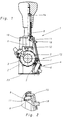
- a hand stamp apparatus designated as a whole with 1, has 2 different printing characters 3 on pressure wheels which are adjustable relative to one another. These printing characters 3 are in accordance with their upward movement following their depression. 3 can be wetted with printing ink by a self-coloring element 4 which can be pivoted against the printing wheels 2 from the position shown in FIG. 1.
- the self-inking element 4 has a felt, foam or a self-inking pad 5, which is held by a pad holder 6, which in turn can be pivoted with the help of a bearing pin 7 in a manner to be described with reference to FIG. 4.
- the rest position of the hand stamp apparatus shown in FIG. 1 1, in which the self-inking element 4 is held at a distance from the printing wheels 2, can be fixed in the manner shown in FIGS. 1 and 2 by a lock 11, which cooperates with a recess 8 on an actuating rod 9 to be pressed down and is adjustable on the stamp housing 10 .
- the back of the printing wheels 2 or the part of the stamp housing 10 containing them is protected by a cover 12.
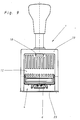
- the cover 12 is at least partially movable against or into the interior of the stamp housing 10 from its normal position shown in FIG. 3 transversely to its extent, so that it assumes the position shown in FIG. 1 after such a movement.
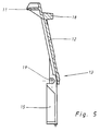
- the cover 12 in the embodiment is pivotable about a lower region 13 in the use position about an approximately horizontal imaginary axis, whereby the in its upper region and gem.
- Fig. 5 u. 6 can be moved approximately horizontally back and forth at its upper edge even with respect to this locking projection 11 arranged above.
- a pivoting of the cover 12 into the interior of the housing thus leads to the locking projection 11 reaching the locking recess 8 inside the housing, because the pivoting path of the cover 12 in the region of its upper edge carrying the locking projection 11 corresponds approximately to the depth of the recess 8, possibly plus a game.
- the two different positions of the locking projection 11 can be seen primarily on the one hand in FIGS. 1 and 2 and on the other hand in FIG. 3.
- the actuating rod 9 cannot be moved further upward from its position shown in FIG. 1, which is carried out by a return spring 14. Thus, the spring 14 remains under tension. If the actuating rod 9 is pushed slightly downwards, the upwardly sloping limitation of the recess 8 can automatically push the correspondingly sloping locking projection 11 out of the recess 8, after which the spring 14 releases the actuating rod 9, which is now released, and the pressure gear train attached to it into that in FIG. 3 illustrated starting position for another stamping operation.
- the locking projection 11 is a rib stiffened plate which is integrally attached to the cover 12.
- this could be mounted on a pivot axis in the area 13.
- it can be elastically deformed and deflected in an advantageous manner and in order to save such a special pivot axis in relation to holding legs 15 that can be fixed in the housing 10 and in turn integrally connected to it.
- Fig. 5 is a cover 12 with multiple functions, which consists of a single piece and thus significantly facilitates assembly.
- two additional holding projections 16 are provided on the cover 12, which in the locked position of the locking projection 11 with counterparts 17 located on the housing 10 can be locked. 7 on both sides of the locking projection 11, locking hooks which can be deflected transversely to the locking movement as additional holding projections 16 which cooperate with counter hooks as counterparts 17 on the stamp housing 10.
- the position shown with strong lines is the open position, while the latched position is indicated by dash-dotted lines in FIGS. 7 and 8.
- the latching forces are strong enough to counteract the elastic deformation of the cover 12, but so small that the downward movement of the actuating rod 9 when the locking projection 11 is pushed back also releases this latching problem.
- a pushbutton 18 projecting from the cover 12 and from the housing 10 is arranged and formed, which facilitates operation.
- This push button 18 jumps so far that it still protrudes beyond the housing 10 even in the locked position.
- the cover 12 has on its holding legs 15 the bearing openings 19 shown in FIGS. that these bearing openings 19 are recesses which are open on one side and which are also closed towards the outside, that is to say are blind holes in the axial direction.
- the journals 7 of the self-coloring element 4 can be inserted into the bearing openings 19 transversely to their axial extent.
- stamp housing 10 and its walls 10a can thus be smooth and unperforated in the area of the pivot bearing 7 of the self-inking pad 4 and 5.
- the Groove width acc. Fig. 7 corresponds approximately to the width of the legs 15 and thus the legs 15 are positively held on both sides.
- the groove ends on the underside can be closed by a releasable base plate 23, on which base plate 23 the legs 15 are then supported with their end faces.
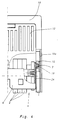
- Fig. 4 illustrates the storage of the self-coloring element 4 in a leg 15, wherein a rocker 24 can be seen, which converts the downward movement of the actuating rod 9 in a known manner into the pivoting movement of the self-coloring element 4.
- the one-piece cover part recognizable in FIG. 5, with its parts contributing to storage and locking, is made of plastic, which favors the one-piece production of this part.
- the cover 12 is therefore a one-piece multifunctional part made of preferably partially elastic plastic, as a result of which the manual actuation of the latching projection 11 on the one hand and the storage of the stamp pad carrier 6 on the other hand are made possible and the housing 10 for covering the printing wheels 2 is also closed.
- the hand stamp apparatus 1 for example with printing marks 3 arranged on printing wheels 2, which can be switched in different ways, in particular also when they are pressed onto the surface to be stamped, has a self-inking element 4 with inking pad 5 in order to automatically wet the printing characters 3 with printing ink, especially in the upward movement that follows after stamping. So that this self-inking element 4 does not remain in an unwanted contact position, which is achieved above all in the top position of the printing wheels 2, there is a rest position of the printing characters 3 in a position slightly lower than their top position, but above the surface to be stamped.
- the self-inking element 4 is arranged at a distance from the printing characters 2 of the printing wheels 3, and this rest position can be determined by a lock 11 which can be adjusted on the stamp housing 10 and which cooperates with a recess 8 on the actuating rod 9 of the hand stamp apparatus 1.
- This lock 11 is arranged as a locking projection on a cover 12 for the stamp housing 10 and this cover 12 can be moved or pivoted together with this locking projection 11 into the interior of the stamp housing 10, so that the locking projection 11 gets into the locking recess 8.
- a separate locking slide with corresponding guides on the stamp housing 10 can be avoided in this way.
Landscapes
- Accessory Devices And Overall Control Thereof (AREA)
- Inking, Control Or Cleaning Of Printing Machines (AREA)
Claims (12)
- Tampon à main (1) comportant sur des supports, par exemple des roulettes d'impression (2), des caractères d'imprimerie (3) qui, notamment lors de leur mouvement vers le haut qui fait suite à leur abaissement, peut être humecté avec de l'encre d'imprimerie par un élément d'encrage automatique (4), sachant qu'au moins une position de repos des caractères d'imprimerie, dans laquelle l'élément d'encrage automatique (4) est maintenu à distance de ceux-ci, peut être enclenchée par un taquet (11) mobile sur le boîtier du tampon (10) qui coopère avec un évidement (8) d'une tige d'actionnement (9) et qu'au moins un côté des caractères d'imprimerie ou des roulettes d'impression est protégé sur le boîtier du tampon (10) par un capot (12), caractérisé en ce que le capot (12) est monté de manière à pouvoir être déplacé au moins par parties transversalement par rapport à son étendue de sa position normale vers l'intérieur du boîtier du tampon (10) et porte en tant que taquet sur sa partie ou zone mobile une saillie pointant vers l'intérieur du boîtier et vers l'évidement (8).
- Tampon à main selon la revendication 1, caractérisé en ce que le capot (12) peut pivoter autour d'une partie (13) qui, en position d'utilisation, se situe en bas et en ce que la saillie de blocage (11) est placée dans la partie supérieure, notamment sur le bord supérieur du capot (12).
- Tampon à main selon la revendication 1 ou 2, caractérisé en ce que la saillie de blocage (11), qui est notamment une baguette ou une plaquette, est fixée d'un seul tenant au capot (12).
- Tampon à main selon l'une des revendications 1 à 3, caractérisé en ce que le capot (12) est monté sur un axe de pivotement ou peut être dévié avec une déformation élastique par rapport à des branches de maintien (15) fixées dans le boîtier (10) et reliées au capot.
- Tampon à main selon l'une des revendications 1 à 4, caractérisé en ce que la saillie de blocage ou une saillie de maintien (16) supplémentaire peut être enclenchée dans un pendant (17) lorsque la saillie de blocage (11) est en position de blocage.
- Tampon à main selon l'une des revendications 1 à 5, caractérisé en ce que des billes d'arrêt, des crochets d'arrêt ou analogues pouvant être déviés transversalement par rapport au mouvement de blocage, qui coopérent avec des évidements, des contre-crochets ou analogues sur le boîtier du tampon (10), sont prévus de part et d'autre de la saillie de blocage (11).
- Tampon à main selon l'une des revendications 1 à 6, caractérisé en ce qu'un bouton poussoir (18) faisant saillie par rapport au capot (12) et, de préférence, par rapport au boîtier du tampon (10) est placé ou réalisé sur le côté extérieur du capot (12), notamment à la hauteur de la saillie de blocage (11).
- Tampon à main notamment selon l'une des revendications précédentes, caractérisé en ce que le capot (12) et/ou ses branches de maintien (15) présentent des logements (19) pour les tenons (7) de l'élément ou du coussin d'encrage automatique ou de son dispositif de fixation.
- Tampon à main selon l'une des revendications 1 à 8, caractérisé en ce que les logements (19) pour les tenons placés sur le dispositif de fixation de l'élément d'encrage automatique (4) sont des évidements dont le bord est ouvert d'un côté, qui, en position montée, sont fermés par une nervure (22) ou une paroi de rainure sur le côté intérieur du boîtier du tampon.
- Tampon à main selon l'une des revendications 1 à 9, caractérisé en ce que le boîtier du tampon est lisse et non perforé dans la zone où le coussin d'encrage automatique est monté de manière pivotante.
- Tampon à main selon l'une des revendications 1 à 10, caractérisé en ce que, sur le côté intérieur du boîtier, des saillies s'étendant de haut en bas en position d'utilisation et faisant saillie vers l'intérieur délimitent une rainure de maintien dans laquelle les branches de maintien (15) du capot (12) peuvent être insérées lors du montage, la largeur de la rainure correspondant approximativement à la largeur des branches (15) et les branches (15) étant ainsi maintenues par engagement positif, et en ce que les extrémités de la rainure qui se situent sur le dessous en position d'utilisation peuvent être fermées par une plaque de fond amovible sur laquelle les branches prennent appui avec leurs faces frontales.
- Tampon à main selon l'une des revendications 1 à 11, caractérisé en ce que le capot est en matière plastique.
Applications Claiming Priority (2)
| Application Number | Priority Date | Filing Date | Title |
|---|---|---|---|
| DE4114451 | 1991-05-03 | ||
| DE4114451A DE4114451C1 (fr) | 1991-05-03 | 1991-05-03 |
Publications (2)
| Publication Number | Publication Date |
|---|---|
| EP0512224A1 EP0512224A1 (fr) | 1992-11-11 |
| EP0512224B1 true EP0512224B1 (fr) | 1995-02-01 |
Family
ID=6430895
Family Applications (1)
| Application Number | Title | Priority Date | Filing Date |
|---|---|---|---|
| EP92104639A Expired - Lifetime EP0512224B1 (fr) | 1991-05-03 | 1992-03-18 | Tampon à main comportant un corps d'encrage automatique |
Country Status (3)
| Country | Link |
|---|---|
| EP (1) | EP0512224B1 (fr) |
| DE (2) | DE4114451C1 (fr) |
| ES (1) | ES2067972T3 (fr) |
Families Citing this family (2)
| Publication number | Priority date | Publication date | Assignee | Title |
|---|---|---|---|---|
| AT522201B1 (de) * | 2019-02-26 | 2021-08-15 | Trodat Gmbh | Stempel mit einer Verschlusskappe und Verschlusskappe für einen Stempel |
| CN115972791B (zh) * | 2023-02-09 | 2025-10-17 | 深圳市银之杰科技股份有限公司 | 一种用于实物印章管控的便携式用印装置 |
Family Cites Families (2)
| Publication number | Priority date | Publication date | Assignee | Title |
|---|---|---|---|---|
| US1555527A (en) * | 1925-03-03 | 1925-09-29 | Wm A Force & Company Inc | Numbering machine |
| DE8423286U1 (de) * | 1984-08-04 | 1984-10-31 | Ernst Reiner GmbH & Co KG, 7743 Furtwangen | Handstempelapparat mit druckraedern |
-
1991
- 1991-05-03 DE DE4114451A patent/DE4114451C1/de not_active Expired - Lifetime
-
1992
- 1992-03-18 ES ES92104639T patent/ES2067972T3/es not_active Expired - Lifetime
- 1992-03-18 EP EP92104639A patent/EP0512224B1/fr not_active Expired - Lifetime
- 1992-03-18 DE DE59201317T patent/DE59201317D1/de not_active Expired - Fee Related
Also Published As
| Publication number | Publication date |
|---|---|
| DE59201317D1 (de) | 1995-03-16 |
| DE4114451C1 (fr) | 1992-10-08 |
| ES2067972T3 (es) | 1995-04-01 |
| EP0512224A1 (fr) | 1992-11-11 |
Similar Documents
| Publication | Publication Date | Title |
|---|---|---|
| EP1280669B1 (fr) | Tampon auto-encreur | |
| EP1673229B1 (fr) | Tampon manuel a encrage automatique | |
| EP1603755B1 (fr) | Tampon auto-encreur a encrage par le haut et receptacle a coussin encreur correspondant | |
| EP2384283B1 (fr) | Timbre et tampon encreur pour un timbre autoencreur | |
| DE69113820T2 (de) | Stempel mit automatischer Einfärbvorrichtung. | |
| EP0782930B1 (fr) | Timbre à main | |
| EP1841599B1 (fr) | Dispositif de fixation de l'axe de rotation d'un porte-caracteres | |
| EP1603754A1 (fr) | Timbre autoencreur a encrage par pression par le haut et receptacle de tampon encreur destine a ce timbre autoencreur | |
| EP2714410B1 (fr) | tampon e procédé pour monter une plaque de tampon | |
| AT501174B1 (de) | Handstempel-typenaggregat | |
| DE69607330T2 (de) | Feuerzeug | |
| DE3334510A1 (de) | Befestigungsmechanismus fuer einen sicherheitsgurt fuer kraftfahrzeuge | |
| EP1255650B1 (fr) | Timbre auto-encreur | |
| EP0512224B1 (fr) | Tampon à main comportant un corps d'encrage automatique | |
| EP3914455B1 (fr) | Tampon manuel comprenant un élément de basculement | |
| DE69117893T2 (de) | Elektronische Schreibmaschine | |
| DE2826991A1 (de) | Handetikettiergeraet zum bedrucken, ausgeben und anbringen von selbsthaftenden etiketten | |
| DE3878178T2 (de) | Trockenrasiergeraet. | |
| DE3103449C2 (fr) | ||
| DE2102385C3 (de) | Tastenschalter-Tableau-Mechanik | |
| DE4243991A1 (de) | Schalterbetätigungsvorrichtung | |
| DE2430496B2 (de) | Schreibgerät mit einer als Klemme ausgebildeten Taschenklammer | |
| EP3752368B1 (fr) | Timbre, notamment timbre dateur | |
| AT526894A1 (de) | Selbstfärbestempel und Verfahren zur Entnahme einer Wendeachse aus einem Selbstfärbestempel | |
| DE2044066A1 (de) | Kipphebelverschluss für Leuchten mit Abdeckung |
Legal Events
| Date | Code | Title | Description |
|---|---|---|---|
| PUAI | Public reference made under article 153(3) epc to a published international application that has entered the european phase |
Free format text: ORIGINAL CODE: 0009012 |
|
| AK | Designated contracting states |
Kind code of ref document: A1 Designated state(s): DE ES FR GB IT |
|
| 17P | Request for examination filed |
Effective date: 19921028 |
|
| 17Q | First examination report despatched |
Effective date: 19940415 |
|
| GRAA | (expected) grant |
Free format text: ORIGINAL CODE: 0009210 |
|
| AK | Designated contracting states |
Kind code of ref document: B1 Designated state(s): DE ES FR GB IT |
|
| GBT | Gb: translation of ep patent filed (gb section 77(6)(a)/1977) |
Effective date: 19950209 |
|
| REF | Corresponds to: |
Ref document number: 59201317 Country of ref document: DE Date of ref document: 19950316 |
|
| REG | Reference to a national code |
Ref country code: ES Ref legal event code: FG2A Ref document number: 2067972 Country of ref document: ES Kind code of ref document: T3 |
|
| ITF | It: translation for a ep patent filed | ||
| ET | Fr: translation filed | ||
| PLBE | No opposition filed within time limit |
Free format text: ORIGINAL CODE: 0009261 |
|
| STAA | Information on the status of an ep patent application or granted ep patent |
Free format text: STATUS: NO OPPOSITION FILED WITHIN TIME LIMIT |
|
| 26N | No opposition filed | ||
| PGFP | Annual fee paid to national office [announced via postgrant information from national office to epo] |
Ref country code: FR Payment date: 20000131 Year of fee payment: 9 |
|
| PGFP | Annual fee paid to national office [announced via postgrant information from national office to epo] |
Ref country code: ES Payment date: 20000308 Year of fee payment: 9 |
|
| PG25 | Lapsed in a contracting state [announced via postgrant information from national office to epo] |
Ref country code: ES Free format text: LAPSE BECAUSE OF NON-PAYMENT OF DUE FEES Effective date: 20010319 |
|
| PG25 | Lapsed in a contracting state [announced via postgrant information from national office to epo] |
Ref country code: FR Free format text: LAPSE BECAUSE OF NON-PAYMENT OF DUE FEES Effective date: 20011130 |
|
| REG | Reference to a national code |
Ref country code: FR Ref legal event code: ST |
|
| REG | Reference to a national code |
Ref country code: GB Ref legal event code: IF02 |
|
| REG | Reference to a national code |
Ref country code: ES Ref legal event code: FD2A Effective date: 20020411 |
|
| PG25 | Lapsed in a contracting state [announced via postgrant information from national office to epo] |
Ref country code: IT Free format text: LAPSE BECAUSE OF NON-PAYMENT OF DUE FEES;WARNING: LAPSES OF ITALIAN PATENTS WITH EFFECTIVE DATE BEFORE 2007 MAY HAVE OCCURRED AT ANY TIME BEFORE 2007. THE CORRECT EFFECTIVE DATE MAY BE DIFFERENT FROM THE ONE RECORDED. Effective date: 20050318 |
|
| PGFP | Annual fee paid to national office [announced via postgrant information from national office to epo] |
Ref country code: DE Payment date: 20070226 Year of fee payment: 16 |
|
| PGFP | Annual fee paid to national office [announced via postgrant information from national office to epo] |
Ref country code: GB Payment date: 20070308 Year of fee payment: 16 |
|
| GBPC | Gb: european patent ceased through non-payment of renewal fee |
Effective date: 20080318 |
|
| PG25 | Lapsed in a contracting state [announced via postgrant information from national office to epo] |
Ref country code: DE Free format text: LAPSE BECAUSE OF NON-PAYMENT OF DUE FEES Effective date: 20081001 |
|
| PG25 | Lapsed in a contracting state [announced via postgrant information from national office to epo] |
Ref country code: GB Free format text: LAPSE BECAUSE OF NON-PAYMENT OF DUE FEES Effective date: 20080318 |