EP0512324B1 - Dispositif d'arrêt - Google Patents
Dispositif d'arrêt Download PDFInfo
- Publication number
- EP0512324B1 EP0512324B1 EP92106889A EP92106889A EP0512324B1 EP 0512324 B1 EP0512324 B1 EP 0512324B1 EP 92106889 A EP92106889 A EP 92106889A EP 92106889 A EP92106889 A EP 92106889A EP 0512324 B1 EP0512324 B1 EP 0512324B1
- Authority
- EP
- European Patent Office
- Prior art keywords
- shut
- housing
- sealing
- constructed
- fixing rings
- Prior art date
- Legal status (The legal status is an assumption and is not a legal conclusion. Google has not performed a legal analysis and makes no representation as to the accuracy of the status listed.)
- Expired - Lifetime
Links
- 238000007789 sealing Methods 0.000 claims description 88
- 239000000463 material Substances 0.000 claims description 15
- 239000011324 bead Substances 0.000 claims description 12
- 230000002093 peripheral effect Effects 0.000 claims description 8
- 238000009434 installation Methods 0.000 claims description 2
- 238000010276 construction Methods 0.000 claims 1
- 230000000284 resting effect Effects 0.000 claims 1
- 230000001419 dependent effect Effects 0.000 description 1
- 238000011161 development Methods 0.000 description 1
- 230000018109 developmental process Effects 0.000 description 1
- 230000000694 effects Effects 0.000 description 1
- 239000013013 elastic material Substances 0.000 description 1
Images



Classifications
-
- B—PERFORMING OPERATIONS; TRANSPORTING
- B65—CONVEYING; PACKING; STORING; HANDLING THIN OR FILAMENTARY MATERIAL
- B65G—TRANSPORT OR STORAGE DEVICES, e.g. CONVEYORS FOR LOADING OR TIPPING, SHOP CONVEYOR SYSTEMS OR PNEUMATIC TUBE CONVEYORS
- B65G53/00—Conveying materials in bulk through troughs, pipes or tubes by floating the materials or by flow of gas, liquid or foam
- B65G53/34—Details
- B65G53/40—Feeding or discharging devices
- B65G53/46—Gates or sluices, e.g. rotary wheels
-
- F—MECHANICAL ENGINEERING; LIGHTING; HEATING; WEAPONS; BLASTING
- F16—ENGINEERING ELEMENTS AND UNITS; GENERAL MEASURES FOR PRODUCING AND MAINTAINING EFFECTIVE FUNCTIONING OF MACHINES OR INSTALLATIONS; THERMAL INSULATION IN GENERAL
- F16K—VALVES; TAPS; COCKS; ACTUATING-FLOATS; DEVICES FOR VENTING OR AERATING
- F16K3/00—Gate valves or sliding valves, i.e. cut-off apparatus with closing members having a sliding movement along the seat for opening and closing
- F16K3/02—Gate valves or sliding valves, i.e. cut-off apparatus with closing members having a sliding movement along the seat for opening and closing with flat sealing faces; Packings therefor
- F16K3/16—Gate valves or sliding valves, i.e. cut-off apparatus with closing members having a sliding movement along the seat for opening and closing with flat sealing faces; Packings therefor with special arrangements for separating the sealing faces or for pressing them together
- F16K3/20—Gate valves or sliding valves, i.e. cut-off apparatus with closing members having a sliding movement along the seat for opening and closing with flat sealing faces; Packings therefor with special arrangements for separating the sealing faces or for pressing them together by movement of the seats
- F16K3/207—Gate valves or sliding valves, i.e. cut-off apparatus with closing members having a sliding movement along the seat for opening and closing with flat sealing faces; Packings therefor with special arrangements for separating the sealing faces or for pressing them together by movement of the seats by means of hydraulic forces
-
- F—MECHANICAL ENGINEERING; LIGHTING; HEATING; WEAPONS; BLASTING
- F16—ENGINEERING ELEMENTS AND UNITS; GENERAL MEASURES FOR PRODUCING AND MAINTAINING EFFECTIVE FUNCTIONING OF MACHINES OR INSTALLATIONS; THERMAL INSULATION IN GENERAL
- F16K—VALVES; TAPS; COCKS; ACTUATING-FLOATS; DEVICES FOR VENTING OR AERATING
- F16K5/00—Plug valves; Taps or cocks comprising only cut-off apparatus having at least one of the sealing faces shaped as a more or less complete surface of a solid of revolution, the opening and closing movement being predominantly rotary
- F16K5/08—Details
- F16K5/14—Special arrangements for separating the sealing faces or for pressing them together
- F16K5/20—Special arrangements for separating the sealing faces or for pressing them together for plugs with spherical surfaces
- F16K5/205—Sealing effected by the flowing medium
Definitions
- the invention relates to a shut-off device for installation in a pneumatic conveyor line for pressurized powdery to fine-grained material to be conveyed, according to the preamble of claim 1.
- a shut-off device of this type is known for example from DE-B-16 00 989 in the form of a flat slide.
- the inflatable sealing elements are arranged in annular grooves in the valve housing, which are undercut to form a trapezoidal cross section.
- the sealing elements which are also approximately trapezoidal in shape in their outer cross-section, are inserted in such a way that the sealing element legs should press against the oblique side walls of the annular grooves when an internal pressure is applied.
- a slide plate acting as a shut-off device is to be pushed, for example, from its shut-off position into its release position, then the internal pressure of the sealing elements is first completely or partially released, whereupon the slide plate can be moved freely; then pressure medium is again introduced into the sealing elements, i.e. these sealing elements are inflated again, so that their sealing surfaces can be pressed against the outside of the slide plate in sealing engagement.
- the sealing elements are not always sufficient are reliably fixed in the device housing or in its annular recesses, which can be the case especially with pneumatic delivery lines with very high delivery pressures; the sealing elements can therefore at least partially detach from their ring recesses and thereby block the shut-off element.
- the invention is therefore based on the object of improving a shut-off device of the type required in the preamble of claim 1 in such a way that even at relatively high pneumatic delivery pressures, the sealing elements are properly sealed and extremely reliably fixed in their housing recesses.
- each sealing element thus has a circumferential, flange-like protruding sealing seal bead in the region of its rear side abutting the recess bottom both on its inner circumferential side (inner circumferential wall) and on its outer circumferential side (outer circumferential wall).
- This type of clamping and sealing fixation ensures, even in such cases, a perfect seal on the one hand and an extremely reliable and permanent clamping connection of the sealing elements on the other hand if this shut-off device according to the invention is exposed to relatively high pneumatic delivery pressures in the area of its shut-off device.
- this extremely reliable seal also has an advantageous effect on the sealing elements themselves if the pressure medium is also subjected to a relatively high internal pressure, i.e. there is no possibility for these sealing elements to separate from their housing recesses or in the area of their rear side lying against the recess bottom to leak.
- this embodiment according to the invention can be used in various embodiments of shut-off devices, in particular in embodiments in which the shut-off device is designed in the form of a slide with a slide plate that can be pushed back and forth or also in the form of a rotationally symmetrical shut-off body, e.g. with rotary valves, ball valves or the like
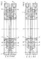
- FIGS. 1 to 4 The exemplary embodiment of the shut-off device in the form of a gate valve illustrated in FIGS. 1 to 4 will first be explained in detail with reference to FIG. 1, the same structural parts being present in FIGS. 2 to 4 and thus provided with the same reference numerals.
- the slide housing 1 belonging to this flat slide is designed in two parts in a manner known per se with the housing parts 1a and 1b; these two housing parts 1 a and 1 b can be detachable in a suitable manner, as indicated only by dash-dotted lines in FIG. 2 be screwed together.
- a slide plate 3 forming a shut-off element is arranged and guided in a suitable manner such that it can be pushed back and forth perpendicularly to the same plane of FIG. 1, as will be explained in more detail below.
- two pipe connections, not shown in more detail, of a pneumatic delivery line are preferably provided approximately in the middle, namely - assuming that pneumatically conveyed material can be conveyed through this gate valve in the direction of arrow 4 - according to FIG. 1 in upper housing part 1a, an input pipe connection 5 and in the lower housing part 1b, an output pipe connection 6, wherein both pipe connections 5 and 6 coaxially oppose each other. Since relatively aggressive material to be conveyed is often to be expected, it is preferred to design each of these two pipe connections 5, 6 in the same manner and in the form of an exchangeable straight wear bushing.
- the pipe connections 5, 6 each have a type of fastening flange 5a and 6a at their axially outer ends, while their straight inner ends 5b and 6b are only so close apart from the slide plate 3 pushed in between that this slide plate 3 can easily be between them can be moved through and optionally guided simultaneously.
- slide plate 3 it is assumed that it can be a flat (plane) or possibly also - in the direction perpendicular to the plane of Fig.1 - slightly curved plate in a manner known per se.
- this slide plate has - Viewed in its transverse direction according to FIG. 1 - a central through opening 7, the clear cross section of which - as shown in FIG. 1 - corresponds exactly to the clear cross section of the inlet and outlet pipe connections 5, 6.
- this slide plate 3 is so long in its longitudinal dimension, that is, viewed perpendicular to the plane of the drawing in FIG. 1, that it extends from the release position shown in FIG.
- the upper side 3a and the lower side 3b of the slide plate 3 are each assigned an annular, inflatable, rubber-elastic sealing element 8 or 9, the upper sealing element 8 in FIG. 1 being the input pipe connection 5 and the lower sealing element 9 surrounds the outlet pipe connection 6 in a ring.
- the sealing element 8 is in an annular (upper) recess 10 in the housing part 1a which is open towards the outer or upper side 3a of the slide plate 3 and the sealing element 9 is arranged in an annular recess 11 in the (lower) housing part 1b which is open towards the outside or underside 3b of the slide plate 3, these recesses having a preferably rectangular cross section, which according to FIG. 1 is on the radially inner side is limited by the corresponding pipe connections 5 and 6.
- Each of these two sealing elements 8, 9 is, so to speak, designed as a hollow profile in such a way that it has a closed sealing surface 8a or 9a facing the slide plate 3, an opposite, at least partially, preferably continuously slit-shaped open rear side 8b or 9b, and one also has closed radially outer peripheral side 8c or 9c and inner peripheral side 8d or 9d.
- the essentially open rear side 8b or 9b of each sealing element 8, 9 lies directly against the bottom 10a or 11a of the associated annular recess 10 or 11.
- a pressure medium channel preferably a compressed air channel 12 or 13 is connected to each recess base 10a, 11a in a manner known per se, via which, as indicated by arrows 14, a suitable pressure medium, preferably compressed air, can be supplied in such a way that the sealing elements 8, 9 are inflated and thereby their sealing surfaces 8a and 9a can be pressed against the outer sides facing them (upper side 3a, lower side 3b) of the slide plate 3 in firm sealing engagement.
- a suitable pressure medium preferably compressed air
- Each sealing element 8, 9 now has in the area of its rear side 8b or 9b both on its inner circumferential side 8d or 9d and on its outer circumferential side 8c or 9c each a circumferential, flange-like outward or inward projecting clamping sealing bead 15, 16 which to a certain extent represent an inner and outer flange-like widening of the rear sides 8b and 9b and thus also abut the bottom 10a, 11a of the associated housing recess 10 and 11, respectively.
- the pressure-released state as illustrated in FIG.
- each sealing element 8, 9 thus has the outer basic shape of a regular rectangle, which is widened in a flange-like manner on its one side, namely on the rear side, by the clamping sealing beads 15, 16, while the sealing surfaces 8a and 9a form smooth, flat surfaces.
- a fixing ring 17 or 18 is likewise arranged on the two circumferential sides of each sealing element 8, 9 within the associated housing recess 10 or 11.
- an outer fixing ring 17 lies closely on the outer circumferential side 8c, 9c of each sealing element 8 and 9, and an inner fixing ring 18 or an inner fixing ring 18 on the inner circumferential side 8d, 9d.
- Each of these fixing rings 17, 18 has, on its circumferential side facing the sealing element and in the vicinity of the recess bottom 10a, 11a, an annular groove 17a or 18a machined therein in such a way that of these ring grooves 17a, 18a the respectively associated or adjacent clamping sealing beads 15 , 16 of the associated sealing element 8 or 9 can be firmly gripped.
- the cross sections of each sealing element 8, 9 and each fixing ring 17, 18 are coordinated with one another such that each sealing element 8, 9 in the pressure-relieved state (shown in FIG.
- each sealing element 8, 9 in the pressure-relieved state are preferably chosen to be somewhat larger such that their clamping sealing beads 15, 16 - in their material thickness - are compressed by the ring grooves 17a, 18a of the associated fixing rings 17 and 18 during assembly and thereby be reliably clamped tightly.
- the fixing rings 17, 18 are detachably fixed in the associated housing recesses 10, 11, preferably screwed detachably by means of screws 19 only indicated by chain-dotted lines.
- each fixing ring 17, 18 can be designed as a single piece in a suitable manner or, if necessary, can also be formed from at least two ring sectors lying closely against one another in the circumferential direction, without this having to be illustrated in detail.
- wear bushings forming the pipe connections 5, 6 are each arranged close to the inner circumferential side of the adjacent inner wear ring 18.
- FIG. 1 it is assumed (as already mentioned in some cases) that the annular sealing elements 8, 9 are in their pressure-relieved state, ie no compressed air is supplied via the compressed air channels 12, 13, but these compressed air channels 12, 13 are preferably - via not explained, but known per se - control valves connected to atmosphere; if necessary, they could possibly also be connected to a vacuum source in order to be able to relieve or retract the seals in a particularly reliable manner, but this is generally not necessary here.
- the slide plate 3 can be displaced perpendicularly to the drawing plane of FIG. 1 in the manner desired in each case, so that its passage opening 7 then either in its release position for a free passage of the conveyed goods (as shown in FIG. 1 to 3) or in their shut-off position (as shown in Fig. 4).
- the sealing elements 8, 9 Since the material is very often conveyed in pneumatic conveying lines with relatively high conveying pressures, it is then also expedient to build up a higher internal pressure in the sealing elements 8, 9, specifically in coordination with the conveying pressure in the associated pneumatic conveying line. At these high delivery pressures and at correspondingly high internal pressures in the sealing elements 8, 9, the sealing sides 8a and 9a will accordingly lie essentially over the entire area on the outer sides 3a and 3b of the slide plate 3 facing them, as illustrated in FIG. 3. In this way, a particularly high reliability of the seal between the sealing elements 8, 9 and the slide plate 3 is achieved even at very high delivery pressures.
- Fig. 4 shows a similar sealing situation as Fig. 3, but the slide plate has been shifted so far - perpendicular to the plane of the drawing - that the free passage of the material to be conveyed through the pipe connections 5, 6 through a full-walled slide plate section 3c is reliably blocked, ie the slide plate 3 is in the shut-off position, while the sealing surfaces 8a, 9a of the sealing elements 8, 9 bear under the entire surface under high pressure on the outer sides of the slide plate 3.
- FIG. 1 An embodiment variant of the exemplary embodiment of a gate valve previously described with reference to FIGS. 1 to 4 is illustrated in FIG.
- the slide housing 1 ' is in turn designed with two detachably screwed housing parts 1'a and 1'b, between which the slide plate 3 is perpendicular to the drawing plane between its shut-off position (similar to FIG. 4) and its release position (in Fig. 5 illustrates) can be moved, wherein in this release position, the passage opening 7 allows the free passage of the material to be conveyed through the inlet and outlet pipe connections 5, 6.
- the ring-shaped sealing elements 8, 9 are likewise designed in the same way as described above and each are fixed in the associated housing recess 10, 11 by means of an outer fixing ring 17 on the one hand and by means of an inner fixing ring 18 'on the other hand, and they can also be made in the same way by means of a pressure medium are inflated to produce the sealing engagement with the slide plate 3, as has been explained with reference to FIGS. 1 to 4.
- the shut-off device according to the invention can also be designed in a similar advantageous manner with respect to the sealing options of its shut-off element in such a way that the shut-off element is designed in the form of a rotationally symmetrical shut-off body, as is the case, for example, with a rotary valve, ball valve or the like.
- a rotary valve, ball valve or the like An example of such an embodiment is explained below with reference to FIG. 6.
- this shut-off device is a ball valve or a ball valve. Similar to the first exemplary embodiment, this ball valve also has a housing 21 which has two housing parts 21a and 21b of approximately the same size, which abut one another approximately in the region of the central plane 21c and, as indicated by dash-dotted lines at 22, are connected to one another by screwing could be.
- a rotationally symmetrical shut-off body 23 is arranged as a shut-off device, which preferably has a diametrical through-bore 24, the clear cross-section of which corresponds to the clear cross-sections of an inlet pipe connection 25 and an outlet pipe connection 26, and can be adjusted coaxially are formed opposite each other in the housing 21.
- the shut-off body 23 is rotatably mounted in the housing 21 in a manner known per se and therefore not illustrated in such a way that it can be rotated or adjusted about an axis of rotation 23b which runs transversely to the through-opening 24 and is only indicated by dash-dotted lines in FIG. In this way, it is also ensured with this ball valve that the shut-off body 23 located in the area between the inlet and outlet pipe connections 25, 26 is moved or rotated between the release position illustrated in FIG. 6 for the free passage of the material to be conveyed and a shut-off position can, in which the free conveyance of the pipe connections 25, 26 is blocked.
- sealing elements 27 and 28 surround the inlet and outlet pipe connections 25, 26 in turn in the vicinity of the shut-off body 23 in an annular manner, and they are also inflatable from rubber-elastic material and, in principle, are designed in the same way as hollow profiles, as is in connection with the Sealing elements 8 and 9 of the first exemplary embodiment have been explained in detail, only with the small difference that the sealing surfaces 27a and 28a of these sealing elements 27, 28 which can be pressed into sealing engagement with the outer sides 23a of the shut-off body 23 are adapted in accordance with the spherical outer contour of the shut-off body 23 . It is also important that, in this exemplary embodiment according to FIG.
- the sealing elements 27, 28 in the region of their rear sides 27b and 28b in turn have outer and inner clamping sealing beads 31 and 32 projecting like a flange. And via these clamping sealing beads 31, 32, the sealing elements 27, 28 are then also fixed in the associated housing recess 29 or 30 in exactly the same way with the aid of closely fitting, clamping inner and outer fixing rings 33, 34, as is described in detail with reference to FIG .1 has been explained.
- a pressure medium, preferably compressed air (arrows 37) can then be introduced into the interior of these sealing elements 27 and 28 via compressed air channels 35, 36 within the housing parts 21a, 21b in order to inflate these sealing elements 27, 28 and their sealing surfaces 27a and 28a firmly and reliably to press against the outer sides 23a of the shut-off body.
- compressed air preferably compressed air
Landscapes
- Engineering & Computer Science (AREA)
- General Engineering & Computer Science (AREA)
- Mechanical Engineering (AREA)
- Sliding Valves (AREA)
Claims (11)
- Dispositif d'arrêt destiné à être monté dans une canalisation de transport pneumatique de produit pulvérulent à granulométrie fine qui est sous pression, comprenant :a) une cage (1, 21) dans laquelle un raccord tubulaire d'entrée (5, 25) et un raccord tubulaire de sortie (6, 26) sont réalisés coaxialement en face l'un de l'autre,b) un organe d'arrêt (3, 23) qui comporte un trou de passage (7, 24) ayant une section libre correspondant à celle des raccords tubulaires d'entrée et de sortie et qui est disposé dans la cage entre ces raccords tubulaires d'entrée et de sortie de manière qu'il soit déplaçable entre une position d'arrêt et une position dans laquelle il libère le passage libre du produit transporté dans ces raccords tubulaires,c) plusieurs éléments d'étanchéité gonflables (8, 9, 27, 28) ayant l'élasticité du caoutchouc et formant des anneaux qui entourent les raccords tubulaires d'entrée et de sortie (5, 6, 25, 26) à proximité de l'organe d'arrêt (3, 23) et qui sont fixés dans des évidements annulaires (10, 11, 29, 30) de la cage (1) qui sont ouverts sur les côtés extérieurs (3a, 3b, 23) de l'organe d'arrêt, chacun de ces éléments d'étanchéité étant conformé en profilé creux de manière qu'il comprenne une surface fermée d'étanchéité (8a, 9a, 27a, 28a) ainsi qu'un côté arrière opposé, au moins partiellement ouvert (8b, 9b, 27b, 28b), qui est appliqué contre le fond de l'évidement annulaire de la cage et par lequel un fluide d'étanchéité servant à serrer les surfaces d'étanchéité contre les côtés extérieurs de l'organe d'arrêt peut être introduit par ce fond de l'évidement dans l'élément d'étanchéité,
caractérisé par les particularités suivantes :d) chaque élément d'étanchéité (8, 9, 27, 28) comporte sur le côté arrière (8b, 9b, 27b, 28b) un bourrelet circonférentiel d'étanchéité par serrage (15, 16, 31, 32) aussi bien sur son côté circonférentiel intérieur (8c, 9c) que sur son côté circonférentiel extérieur (8d, 9d),e) un anneau de fixation (17, 18, 33, 34) est appliqué étroitement d'une part contre le côté circonférentiel extérieur et d'autre part contre le côté circonférentiel intérieur de chaque élément d'étanchéité (8, 9, 27, 28), les deux anneaux de fixation comportant des rainures annulaires (17a, 18a) qui chapeautent étroitement les bourrelets d'étanchéité par serrage et étant fixées de manière amovible dans l'évidement correspondant de la cage. - Dispositif d'arrêt selon la revendication 1, caractérisé en ce que, lorsqu'il est à l'état décomprimé, chaque élément d'étanchéité (8, 9) forme avec les anneaux de fixation (17, 18) étroitement appliqués contre ses deux côtés circonférentiels (8c, 8d, 9c, 9d) une section globale qui remplit totalement et à fleur la section libre de l'évidement correspondant (10, 11) de la cage.
- Dispositif d'arrêt selon la revendication 2, caractérisé en ce que la cote axiale maximale (a) des anneaux de fixation (17, 18) coïncide avec la profondeur des évidements (10, 11) de la cage et les bourrelets d'étanchéité par serrage (15, 16) de chaque élément d'étanchéité (8, 9) sont comprimés par les rainures annulaires (17a, 18a) des anneaux correspondants de fixation et sont étroitement serrés de manière étanche.
- Dispositif d'arrêt selon la revendication 1, caractérisé en ce que les anneaux de fixation (17, 18, 33, 34) sont fixés par boulonnage dans les évidements correspondants (10, 11, 29, 30) de la cage.
- Dispositif d'arrêt selon la revendication 1, caractérisé en ce que chaque anneau de fixation est réalisé en une pièce.
- Dispositif d'arrêt selon la revendication 1, caractérisé en ce que chaque anneau de fixation est formé d'au moins deux secteurs annulaires.
- Dispositif d'arrêt selon la revendication 1, dans lequel chaque raccord tubulaire (5, 6) placé dans la cage (1) est réalisé sous la forme d'un manchon d'usure interchangeable, caractérisé en ce que les manchons d'usure sont disposés de manière à être étroitement appliqués contre le côté circonférentiel intérieur de l'anneau intérieur voisin de fixation (18).
- Dispositif d'arrêt selon la revendication 1, dans lequel chaque raccord tubulaire (5, 6) placé dans la cage (1') est réalisé sous la forme d'un manchon interchangeable d'usure, caractérisé en ce que chaque manchon d'usure est réalisé en une pièce avec l'anneau intérieur voisin de fixation (18').
- Dispositif d'arrêt selon la revendication 8, caractérisé en ce que les anneaux intérieurs de fixation et les manchons d'usure sont prévus de manière qu'ils constituent également une racle étroitement appliquée contre le côté extérieur de l'organe d'arrêt.
- Dispositif d'arrêt selon la revendication 1, caractérisé par la réalisation sous forme d'une vanne d'arrêt dont l'organe d'arrêt est constitué d'une plaque coulissante (3) déplaçable alternativement.
- Dispositif d'arrêt selon la revendication 1, caractérisé en ce que l'organe d'arrêt est réalisé sous la forme d'un corps d'arrêt symétrique de révolution (23) qui est déplaçable autour d'un axe de rotation (23b) qui est perpendiculaire au trou de passage (24).
Applications Claiming Priority (2)
| Application Number | Priority Date | Filing Date | Title |
|---|---|---|---|
| DE4114902A DE4114902A1 (de) | 1991-05-07 | 1991-05-07 | Absperrvorrichtung |
| DE4114902 | 1991-05-07 |
Publications (2)
| Publication Number | Publication Date |
|---|---|
| EP0512324A1 EP0512324A1 (fr) | 1992-11-11 |
| EP0512324B1 true EP0512324B1 (fr) | 1994-10-12 |
Family
ID=6431175
Family Applications (1)
| Application Number | Title | Priority Date | Filing Date |
|---|---|---|---|
| EP92106889A Expired - Lifetime EP0512324B1 (fr) | 1991-05-07 | 1992-04-22 | Dispositif d'arrêt |
Country Status (2)
| Country | Link |
|---|---|
| EP (1) | EP0512324B1 (fr) |
| DE (2) | DE4114902A1 (fr) |
Families Citing this family (8)
| Publication number | Priority date | Publication date | Assignee | Title |
|---|---|---|---|---|
| DE9214482U1 (de) * | 1992-10-27 | 1992-12-17 | Schütte-Meyer Schüttgutabsperrtechnik GmbH, 5860 Iserlohn | Vorrichtung zum Öffnen und Schließen einer Durchtrittsöffnung für fließfähiges Fördergut, insbesondere Schüttgut |
| DE19824578A1 (de) * | 1998-06-02 | 1999-12-16 | Dietrich Zosel | Absperrschieber |
| DE102008017099B4 (de) * | 2008-04-02 | 2018-06-14 | Torsten Burgmer | Flachschieber |
| DE102014106001B4 (de) * | 2014-04-29 | 2022-09-29 | Z & J Technologies Gmbh | Leitrohrschieber für chemische und petrochemische Anlagen |
| DE102015110113B4 (de) | 2015-06-24 | 2018-06-14 | Burgmer Apparatebau GmbH | Absperrschieber |
| GB2581849B (en) * | 2019-03-01 | 2023-06-28 | Schenck Process Europe Gmbh | Valve with pressure seal protection |
| CN110107706B (zh) * | 2019-06-13 | 2024-07-05 | 集美大学 | 一种自清洁插板阀 |
| CN116241679B (zh) * | 2023-03-03 | 2023-09-08 | 江苏远洋阀门智控股份有限公司 | 快速截断介质气液动球阀 |
Family Cites Families (9)
| Publication number | Priority date | Publication date | Assignee | Title |
|---|---|---|---|---|
| US3222076A (en) * | 1962-04-24 | 1965-12-07 | Woodward Iron Company | Pipe joint packing |
| US3339886A (en) * | 1964-12-01 | 1967-09-05 | M & J Valve Co | Valve construction |
| DE1751550C3 (de) * | 1968-06-18 | 1975-04-17 | Messerschmitt-Boelkow-Blohm Gmbh, 8000 Muenchen | Dichtung zwischen dem Einlauf eines Strahltriebwerkes und einem zellenfesten Aufnahmering des Einlaufgehäuses |
| FR2500103B2 (fr) * | 1974-04-09 | 1985-12-13 | Socea Balency | Vanne a registre coulissant, notamment pour le transport par voie pneumatique des ordures menageres |
| DE2623822A1 (de) * | 1976-05-28 | 1977-12-08 | Sapco Systemanalyse & Projektb | Vakuumdichter verschluss |
| CA1185585A (fr) * | 1981-04-28 | 1985-04-16 | John W. Ells | Garniture d'etancheite |
| DE3248228A1 (de) * | 1982-12-27 | 1984-06-28 | Bühler-Miag GmbH, 3300 Braunschweig | Absperrvorrichtung fuer pneumatische foerdersysteme zum transport rieselfaehiger schuettgueter |
| DE3804271A1 (de) * | 1988-02-11 | 1989-08-24 | Krupp Polysius Ag | Drehschieberanordnung |
| DE4000139C3 (de) * | 1990-01-04 | 1997-03-13 | Schuette Meyer Schuettgutabspe | Flachschieber, insbes. Schüttgutschieber |
-
1991
- 1991-05-07 DE DE4114902A patent/DE4114902A1/de not_active Withdrawn
-
1992
- 1992-04-22 DE DE59200618T patent/DE59200618D1/de not_active Expired - Fee Related
- 1992-04-22 EP EP92106889A patent/EP0512324B1/fr not_active Expired - Lifetime
Also Published As
| Publication number | Publication date |
|---|---|
| DE59200618D1 (de) | 1994-11-17 |
| EP0512324A1 (fr) | 1992-11-11 |
| DE4114902A1 (de) | 1992-11-12 |
Similar Documents
| Publication | Publication Date | Title |
|---|---|---|
| DE2753836C2 (de) | Abgedichtete Rohrverbindung | |
| ZA200102485B (en) | Device for arranging, clamping or contracting a ring-shaped securing mechanism. | |
| CH668629A5 (de) | Rohrverschraubung mit beruehrungsdichtung. | |
| DE9216369U1 (de) | Preßwerkzeug | |
| DE10060004B4 (de) | Absperrorgan mit einer verschwenkbaren Drehklappe und einer an einem Stützring gehaltenen, entropieelastischen Ringdichtung | |
| EP1095206B1 (fr) | Dispositif d'etancheite | |
| DE102023117369B4 (de) | Kugelventil einer Kältemittelventileinrichtung für eine Klimaanlage | |
| EP0512324A1 (fr) | Dispositif d'arrêt | |
| EP0135042B1 (fr) | Dispositif de vanne à tiroir | |
| EP1361380B1 (fr) | Dispositif d'étanchéité | |
| DE2605109A1 (de) | Durchflussteuervorrichtung | |
| DE602004002083T2 (de) | O-Ring für Pressverbindungen | |
| DE102011112050A1 (de) | Modularer Pressverbinder | |
| EP0801015A2 (fr) | Système d'étanchéité | |
| DE69121548T2 (de) | Verbesserte Bandschelle mit keilförmigen, geschlitzten Nocken | |
| DE8524858U1 (de) | Doppeltellerventil | |
| EP0655558B1 (fr) | Soupape pneumatique avec au moins deux modules fixés l'un à l'autre | |
| DE10049047A1 (de) | Verfahren zum Herstellen einer Nockenwelle und danach hergestellte Nockenwelle | |
| DE2235640A1 (de) | Drehschieber und dichtung hierfuer | |
| EP1336780B1 (fr) | Joint secondaire pour dispositif de joint d'étanchéité à bague glissante | |
| DE4417669A1 (de) | Absperrarmatur zum Absperren einer Strömung | |
| EP1517072B1 (fr) | Vanne | |
| DE9012109U1 (de) | Quetschventil | |
| DE10150833B4 (de) | Gummielastische Dichtung, insbesondere für Außenschwingtüren bei Fahrzeugen | |
| DE29711095U1 (de) | Spannmuffe zur axialen Verbindung von zwei stirnseitig aneinanderstoßenden runden Rohrkörpern |
Legal Events
| Date | Code | Title | Description |
|---|---|---|---|
| PUAI | Public reference made under article 153(3) epc to a published international application that has entered the european phase |
Free format text: ORIGINAL CODE: 0009012 |
|
| AK | Designated contracting states |
Kind code of ref document: A1 Designated state(s): DE ES FR GB IT |
|
| 17P | Request for examination filed |
Effective date: 19921029 |
|
| 17Q | First examination report despatched |
Effective date: 19940317 |
|
| GRAA | (expected) grant |
Free format text: ORIGINAL CODE: 0009210 |
|
| AK | Designated contracting states |
Kind code of ref document: B1 Designated state(s): DE ES FR GB IT |
|
| PG25 | Lapsed in a contracting state [announced via postgrant information from national office to epo] |
Ref country code: IT Free format text: LAPSE BECAUSE OF FAILURE TO SUBMIT A TRANSLATION OF THE DESCRIPTION OR TO PAY THE FEE WITHIN THE PRE;WARNING: LAPSES OF ITALIAN PATENTS WITH EFFECTIVE DATE BEFORE 2007 MAY HAVE OCCURRED AT ANY TIME BEFORE 2007. THE CORRECT EFFECTIVE DATE MAY BE DIFFERENT FROM THE ONE RECORDED.SCRIBED TIME-LIMIT Effective date: 19941012 Ref country code: ES Free format text: THE PATENT HAS BEEN ANNULLED BY A DECISION OF A NATIONAL AUTHORITY Effective date: 19941012 |
|
| REF | Corresponds to: |
Ref document number: 59200618 Country of ref document: DE Date of ref document: 19941117 |
|
| ET | Fr: translation filed | ||
| GBT | Gb: translation of ep patent filed (gb section 77(6)(a)/1977) |
Effective date: 19950105 |
|
| PLBE | No opposition filed within time limit |
Free format text: ORIGINAL CODE: 0009261 |
|
| STAA | Information on the status of an ep patent application or granted ep patent |
Free format text: STATUS: NO OPPOSITION FILED WITHIN TIME LIMIT |
|
| 26N | No opposition filed | ||
| PG25 | Lapsed in a contracting state [announced via postgrant information from national office to epo] |
Ref country code: FR Effective date: 19951229 |
|
| PG25 | Lapsed in a contracting state [announced via postgrant information from national office to epo] |
Ref country code: DE Effective date: 19960103 |
|
| REG | Reference to a national code |
Ref country code: FR Ref legal event code: ST |
|
| PG25 | Lapsed in a contracting state [announced via postgrant information from national office to epo] |
Ref country code: GB Effective date: 19960422 |
|
| GBPC | Gb: european patent ceased through non-payment of renewal fee |
Effective date: 19960422 |