EP0801015A2 - Système d'étanchéité - Google Patents
Système d'étanchéité Download PDFInfo
- Publication number
- EP0801015A2 EP0801015A2 EP97104035A EP97104035A EP0801015A2 EP 0801015 A2 EP0801015 A2 EP 0801015A2 EP 97104035 A EP97104035 A EP 97104035A EP 97104035 A EP97104035 A EP 97104035A EP 0801015 A2 EP0801015 A2 EP 0801015A2
- Authority
- EP
- European Patent Office
- Prior art keywords
- wall
- sealing
- valve cone
- inlet
- cone
- Prior art date
- Legal status (The legal status is an assumption and is not a legal conclusion. Google has not performed a legal analysis and makes no representation as to the accuracy of the status listed.)
- Granted
Links
Images

Classifications
-
- B—PERFORMING OPERATIONS; TRANSPORTING
- B65—CONVEYING; PACKING; STORING; HANDLING THIN OR FILAMENTARY MATERIAL
- B65G—TRANSPORT OR STORAGE DEVICES, e.g. CONVEYORS FOR LOADING OR TIPPING, SHOP CONVEYOR SYSTEMS OR PNEUMATIC TUBE CONVEYORS
- B65G69/00—Auxiliary measures taken, or devices used, in connection with loading or unloading
- B65G69/18—Preventing escape of dust
- B65G69/181—Preventing escape of dust by means of sealed systems
- B65G69/183—Preventing escape of dust by means of sealed systems with co-operating closure members on each of the parts of a separable transfer channel
-
- B—PERFORMING OPERATIONS; TRANSPORTING
- B65—CONVEYING; PACKING; STORING; HANDLING THIN OR FILAMENTARY MATERIAL
- B65D—CONTAINERS FOR STORAGE OR TRANSPORT OF ARTICLES OR MATERIALS, e.g. BAGS, BARRELS, BOTTLES, BOXES, CANS, CARTONS, CRATES, DRUMS, JARS, TANKS, HOPPERS, FORWARDING CONTAINERS; ACCESSORIES, CLOSURES, OR FITTINGS THEREFOR; PACKAGING ELEMENTS; PACKAGES
- B65D90/00—Component parts, details or accessories for large containers
- B65D90/54—Gates or closures
- B65D90/62—Gates or closures having closure members movable out of the plane of the opening
- B65D90/626—Gates or closures having closure members movable out of the plane of the opening having a linear motion
-
- F—MECHANICAL ENGINEERING; LIGHTING; HEATING; WEAPONS; BLASTING
- F16—ENGINEERING ELEMENTS AND UNITS; GENERAL MEASURES FOR PRODUCING AND MAINTAINING EFFECTIVE FUNCTIONING OF MACHINES OR INSTALLATIONS; THERMAL INSULATION IN GENERAL
- F16J—PISTONS; CYLINDERS; SEALINGS
- F16J15/00—Sealings
- F16J15/46—Sealings with packing ring expanded or pressed into place by fluid pressure, e.g. inflatable packings
-
- B—PERFORMING OPERATIONS; TRANSPORTING
- B65—CONVEYING; PACKING; STORING; HANDLING THIN OR FILAMENTARY MATERIAL
- B65D—CONTAINERS FOR STORAGE OR TRANSPORT OF ARTICLES OR MATERIALS, e.g. BAGS, BARRELS, BOTTLES, BOXES, CANS, CARTONS, CRATES, DRUMS, JARS, TANKS, HOPPERS, FORWARDING CONTAINERS; ACCESSORIES, CLOSURES, OR FITTINGS THEREFOR; PACKAGING ELEMENTS; PACKAGES
- B65D2590/00—Component parts, details or accessories for large containers
- B65D2590/54—Gates or closures
- B65D2590/542—Gates or closures special sealing means or means for improving sealing
Definitions
- the invention relates to a sealing system for the outlet or inlet of a container or the like, to which an inlet or outlet arrangement, a pipeline, a decanting container or the like can be connected, the container and the inlet or Spout arrangement or the like. Are movable relative to each other.
- an inflatable sealing ring can be attached to the radially outer part and pressed under air pressure against the radially inner part.
- this gives inexpensive options for supplying the compressed air from the outside.
- the service life of such seals is relatively short, so that they hardly differ from those of elastic seals with an essentially predetermined shape.
- the invention is therefore based on the object to provide an effective seal with a long service life on a system of the type mentioned. Surprisingly, this is achieved in that an elastically deformable sealing body having at least one cavity which can be acted upon by a compressed fluid source, compressed air source or the like is provided between the container and the outlet arrangement or the like and the sealing body expands outwards on a wall located on the inside supports.
- the sealing system is particularly advantageous if, according to a further feature of the invention, the sealing body is a, preferably inflatable, sealing ring, which is supported on a radially inner, preferably rigid, wall, radially outward, against an, preferably relatively movable, wall.
- a sealing system in particular on a container for free-flowing bulk material, which has an outlet cone, an outlet arrangement connected to it, for example in the form of an outlet funnel or a decanting container, that the rigid wall is the wall of a valve cone and the sealing ring is provided against a wall of a relatively movable funnel which forms the inlet or outlet arrangement and is pressed together.
- a free space in particular an annular slot, be provided in the radial direction outwards, which is delimited on the outside by the wall of the relatively movable valve cone. This ensures sufficient space for the sealing ring during its expansion phase. A uniform expansion and compression of the sealing ring against its opposing contact surface is achieved, which contributes significantly to the good functioning of the sealing system.
- a further embodiment of the invention provides the outside of the relatively movable wall as a contact surface for the inlet or outlet arrangement and this wall is preferably inclined to the axis of the container or the like, this results in an advantageously simple construction.
- the inflatable sealing ring for sealing the rigid wall of the valve cone movable relative to the wall and the outlet funnel provided with a flanged support wall Bead forms.
- the sealing ring forms a sealing surface, preferably inflatable, has extension.
- a double seal is thus advantageously achieved. Due to the one-piece design, assembly is easy and a high accuracy of fit is achieved.
- a very good seal of the components brought into operative connection is achieved according to a further preferred embodiment of the invention in that the preferably radially outer wall has at least one annular groove for receiving the sealing extension.
- This ring groove can also be effective due to the shape of a ring indentation for receiving the sealing extension.
- the construction of the sealing system is also kept very simple in that, according to a further preferred embodiment of the invention, the valve cone has a conical edge designed for fastening the sealing extension. In this way, positive locking can be carried out in a simple manner in an advantageous manner.
- a supply channel is provided connected to the valve cone.
- the structural design for the supply of the pressurized fluid or the pressurized air can be particularly simple and stable if, according to a further feature of the invention, a single annular cone-shaped cavity of the valve cone is provided as the supply duct.
- a plurality of individual lines which are guided radially, preferably downwards, are provided for supplying the pressure fluid, the compressed air or the like to the at least one cavity of the sealing ring and / or in the valve cone stable, reliable and reliable construction.
- a control device for acting on the at least one cavity of the sealing ring, which control device is preferably synchronous or via a drive of the valve cone Sensor, such as preferably a stylus, can be activated for the position, in particular, of the outlet part in relation to the outer wall.
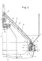
- FIG. 1 shows a container 1 with a free-flowing bulk material 4 receiving interior 3, an outlet cone 9 and an outlet arrangement 2 connected to it in an outlet region 10.
- the outlet arrangement 2 is conventionally an outlet funnel 6, but could be connected to the silo-like container 1 by a ( smaller) transfer container be formed.
- a cooperating with the underside of the outlet cone 9 can be brought from the closed position shown on the right in FIG. 1 into the open position shown on the left with the aid of a fluidic drive D, such as a pneumatic cylinder
- a fluidic drive D such as a pneumatic cylinder
- a valve cone 12 located on a container axis A is provided which, after opening (left in FIG. 1), releases an annular gap between its lower edge 13 and the wall of the outlet cone 9, through which material, for example powder, can escape.
- the arrangement 5 is for sealing between (optionally in the case of a decanting container), which can be attached to the outlet cone 9 and is therefore movable relative to this outlet part 6 or the outlet cone 9 and the lower edge 13 of the valve cone 12 that is movable relative thereto from sealing rings of a predetermined, albeit elastically deformable shape, which is naturally subject to heavy wear, not least also under the influence of the possibly abrasive powder material 4, and thus can only imperfectly perform its sealing function.
- an inflatable seal in the form of a sealing ring 14 with a cavity 15 connected to a fluid source, in particular a source of compressed air, is now arranged in such a way that the sealing ring 14 with a radially inner wall is attached to a rigid wall 16 of one of the relatively movable ones Parts, e.g. B. the valve cone 12, but has a free space in the radial direction towards the outside, here in the form of an annular slot S, in which it seals against at least one radially outer wall 17 of at least one further relatively movable part (relative to the valve cone 12 ), namely here at the edge of the discharge funnel 9.
- a fluid source in particular a source of compressed air
- the free space S does not necessarily have to extend parallel to the axis A, rather the wall 17 could the wall 16 and the inflatable sealing ring 14 lie radially on the outside.
- the illustrated embodiment achieves a double seal with the sealing ring 14 and thus the construction is also simplified and improved in terms of construction compared to the known construction.
- this is done in such a way that the outside of the wall 17 simultaneously serves as a contact surface for the outlet part 6, which lies against the outside of the wall 17 with a flanged support wall 18.
- sealing ring 14 Because the sealing ring 14 is supported firmly on the radially inner wall 16, its sealing function cannot be called into question at this point by a movement during inflation. A movement of the sealing ring 14 or its bead 14 'takes place only in the radial direction to the outside, the expansion of the ring 14 by the internal pressure let into the cavity 15 ensuring smooth and wrinkle-free application to the walls 17 and 18.
- the sealing ring forms a sealing surface 30 Has extension 31.
- This extension could also be made inflatable in one embodiment, which would be easily possible by a corresponding branching of an inlet pipe 32 connected to the channel 19, but this will not be absolutely necessary.
- extension 31 and the sealing ring 14 are radially inflatable. It is clear, however, that the one-story design makes assembly easier and increases the accuracy of fit.
- the radially outer wall can be a different from the shown conical wall, z. B. with a ring indentation for receiving the inflated sealing element 31; however, a conical design in the area of the radially acting seals is preferred. It is also preferred if, as shown, the conical edge 13 of the valve cone 12 is used for the form-fitting fastening of the sealing element 31.
- this problem is solved in a simple manner such that a supply channel 19 is connected to the valve plug 12, in that the plug 12 has an inner wall 20, for example.
- This solution is particularly advantageous in connection with the pneumatic drive D (FIG. 11) because the compressed air is so easy from the areas of the axis A from the drive unit D or parallel to it Feed channel 19 and thus can be directed into the cavity 15.
- a parallel line (hose) 21 is provided, the upper end of which is attached to an actuating cone 21 for the valve cone 12 in such a way that the air supplied by it via a transverse duct 23 to a central duct 24 and from there via a further transverse duct 25 in the feed channel 19 is blown.
- the feed channel 19 can be a single annular cone-shaped cavity of the valve cone 12 or can be formed by one or more individual lines which are guided radially downwards.
- connection of the drive D or the actuating cone 21 can also be easily synchronized with the actuation of the valve cone 12 by the connection with the drive D, so that air is let into the cavity 15 when the valve cone is in its lower closed position ( see the right position in Fig. 1).
- a sensor e.g. B. a stylus can be provided to monitor the attachment of the outlet part and its flanged wall 18 to the wall 17 and only then to allow the compressed air for the cavity to flow.
- a container closure which can be moved up and down in the form of the valve cone 12, but closures rotating or pivoting about a horizontal or vertical axis could also be used, as are known per se in the relevant art.
- a shaft in particular in the case of a vertical shaft, can be hollow and take over the function of the hose 22 as a supply line for pressure medium, in particular compressed air.
- the drive of the closure does not necessarily have to be formed by a cylinder D, although this has the advantages explained above. It would also be possible to use a rotary motor for rotating the shafts mentioned, which could also be a fluid or a pneumatic motor. In the case of an electric motor, a reduction gear with the closing shaft and / or a transmission gear with a blower or a pump for pressure fluid could be provided to supply the seal (s) 14 and / or 31. Rotary motors would also not have to be arranged in alignment with the locking axis A, but could, particularly when using a hollow shaft, have a horizontal motor shaft - with the motor arranged laterally.
Landscapes
- Engineering & Computer Science (AREA)
- Mechanical Engineering (AREA)
- General Engineering & Computer Science (AREA)
- Physics & Mathematics (AREA)
- Architecture (AREA)
- Fluid Mechanics (AREA)
- Sealing Devices (AREA)
- Closures For Containers (AREA)
- Glass Compositions (AREA)
- Electrical Discharge Machining, Electrochemical Machining, And Combined Machining (AREA)
- Manufacturing Of Electric Cables (AREA)
Priority Applications (1)
| Application Number | Priority Date | Filing Date | Title |
|---|---|---|---|
| US08/853,646 US5893567A (en) | 1997-03-11 | 1997-05-09 | Sealing system for sealing an opening |
Applications Claiming Priority (3)
| Application Number | Priority Date | Filing Date | Title |
|---|---|---|---|
| CH92696 | 1996-04-12 | ||
| CH926/96 | 1996-04-12 | ||
| CH92696 | 1996-04-12 |
Publications (3)
| Publication Number | Publication Date |
|---|---|
| EP0801015A2 true EP0801015A2 (fr) | 1997-10-15 |
| EP0801015A3 EP0801015A3 (fr) | 1998-07-15 |
| EP0801015B1 EP0801015B1 (fr) | 1999-11-24 |
Family
ID=4198391
Family Applications (1)
| Application Number | Title | Priority Date | Filing Date |
|---|---|---|---|
| EP97104035A Expired - Lifetime EP0801015B1 (fr) | 1996-04-12 | 1997-03-11 | Système d'étanchéité |
Country Status (3)
| Country | Link |
|---|---|
| EP (1) | EP0801015B1 (fr) |
| AT (1) | ATE186895T1 (fr) |
| DE (1) | DE59700743D1 (fr) |
Cited By (7)
| Publication number | Priority date | Publication date | Assignee | Title |
|---|---|---|---|---|
| WO2000026120A3 (fr) * | 1998-10-29 | 2000-08-10 | Matcon R & D Ltd | Appareil de manutention de matieres |
| EP1145999A1 (fr) * | 2000-04-10 | 2001-10-17 | ANAG A. Nussbaumer AG | Dispositif de remplissage d' un récipient, récipient et couvercle correspodantes |
| EP1348644A1 (fr) * | 2002-03-14 | 2003-10-01 | AT Anlagetechnik AG | Dispositif pour transférer des produits fluides |
| CN105347065A (zh) * | 2015-12-04 | 2016-02-24 | 中冶焦耐工程技术有限公司 | 一种移动设备进、出料口抑尘密封方法及装置 |
| CN107508552A (zh) * | 2017-09-19 | 2017-12-22 | 青海天创新能源科技有限公司 | 一种光伏电站现场组件隐性缺陷检测装置暗室 |
| CN110498264A (zh) * | 2019-09-20 | 2019-11-26 | 北京诚益通科技有限公司 | 一种浮动密封自动对接系统 |
| DE102010052094B4 (de) * | 2010-11-20 | 2020-04-23 | Zeppelin Systems Gmbh | Seilbahngestütztes Transportsystem für Schüttgüter mit verschmutzungsgeschützten Schüttgutbehältern |
Families Citing this family (1)
| Publication number | Priority date | Publication date | Assignee | Title |
|---|---|---|---|---|
| GB9812204D0 (en) | 1998-06-05 | 1998-08-05 | Matcon R & D Ltd | A seal device |
Family Cites Families (5)
| Publication number | Priority date | Publication date | Assignee | Title |
|---|---|---|---|---|
| US4469152A (en) * | 1979-10-25 | 1984-09-04 | Borg-Warner Chemicals, Inc. | Dust-tight hatch closure assembly |
| GB9126664D0 (en) * | 1991-12-16 | 1992-02-12 | Material Control Eng Ltd | A container and a system incorporating same |
| DE4416009A1 (de) * | 1994-05-06 | 1995-11-09 | Hausach Umformtechnik | Entleereinrichtung für Schüttgut-Container |
| AU712291B2 (en) * | 1994-07-11 | 1999-11-04 | Matcon (R & D) Limited | Material handling apparatus |
| DE29503812U1 (de) * | 1995-03-09 | 1995-08-24 | Gesellschaft für Planung, Maschinen- und Mühlenbau Erhard Muhr mbH, 83098 Brannenburg | Lose-Beladesystem mit integrierter Filtereinheit und Dichtsystem |
-
1997
- 1997-03-11 AT AT97104035T patent/ATE186895T1/de not_active IP Right Cessation
- 1997-03-11 DE DE59700743T patent/DE59700743D1/de not_active Expired - Lifetime
- 1997-03-11 EP EP97104035A patent/EP0801015B1/fr not_active Expired - Lifetime
Cited By (8)
| Publication number | Priority date | Publication date | Assignee | Title |
|---|---|---|---|---|
| WO2000026120A3 (fr) * | 1998-10-29 | 2000-08-10 | Matcon R & D Ltd | Appareil de manutention de matieres |
| EP1145999A1 (fr) * | 2000-04-10 | 2001-10-17 | ANAG A. Nussbaumer AG | Dispositif de remplissage d' un récipient, récipient et couvercle correspodantes |
| EP1348644A1 (fr) * | 2002-03-14 | 2003-10-01 | AT Anlagetechnik AG | Dispositif pour transférer des produits fluides |
| DE102010052094B4 (de) * | 2010-11-20 | 2020-04-23 | Zeppelin Systems Gmbh | Seilbahngestütztes Transportsystem für Schüttgüter mit verschmutzungsgeschützten Schüttgutbehältern |
| CN105347065A (zh) * | 2015-12-04 | 2016-02-24 | 中冶焦耐工程技术有限公司 | 一种移动设备进、出料口抑尘密封方法及装置 |
| CN107508552A (zh) * | 2017-09-19 | 2017-12-22 | 青海天创新能源科技有限公司 | 一种光伏电站现场组件隐性缺陷检测装置暗室 |
| CN107508552B (zh) * | 2017-09-19 | 2023-11-14 | 青海天创新能源科技有限公司 | 一种光伏电站现场组件隐性缺陷检测装置暗室 |
| CN110498264A (zh) * | 2019-09-20 | 2019-11-26 | 北京诚益通科技有限公司 | 一种浮动密封自动对接系统 |
Also Published As
| Publication number | Publication date |
|---|---|
| ATE186895T1 (de) | 1999-12-15 |
| EP0801015B1 (fr) | 1999-11-24 |
| EP0801015A3 (fr) | 1998-07-15 |
| DE59700743D1 (de) | 1999-12-30 |
Similar Documents
| Publication | Publication Date | Title |
|---|---|---|
| DE69423617T2 (de) | Membranventil | |
| DE3042887C2 (de) | Doppelsitzventil mit Leckablauf | |
| EP4168223A1 (fr) | Buse pour distribuer du béton, du mortier ou similaire | |
| EP0758540A2 (fr) | Pièce à main médical à turbine, in particulier pour applications dentaires | |
| DE4020513C3 (de) | Vorrichtung zur Beförderung von Feststoffe enthaltendem Material zwischen Räumen unterschiedlichen Drucks | |
| DE4004094A1 (de) | Verschlussvorrichtung fuer eine rohrleitung zum transport von losen produkten | |
| DE3306526C2 (fr) | ||
| EP0987476A2 (fr) | Soupape, en particulier une soupape à double siège | |
| DE102023117369B4 (de) | Kugelventil einer Kältemittelventileinrichtung für eine Klimaanlage | |
| EP0801015B1 (fr) | Système d'étanchéité | |
| EP0226659B1 (fr) | Filtre-presse | |
| EP2203667B1 (fr) | Soupape a double siege avec possibilite de nettoyage de siege et procede de nettoyage de cette soupape | |
| DE10149395A1 (de) | Dreh- und/oder Schwenk-Antrieb mit einem Faltenbelag | |
| DE2342069C3 (de) | Kugelhahn mit frei beweglichen Dichtungssitzringen | |
| DE2605109A1 (de) | Durchflussteuervorrichtung | |
| DE2510384C3 (de) | Zahnärztliches Handstück | |
| DE2349304C3 (de) | Mit Druckflüssigkeit betriebener Zahnradmotor | |
| EP0512324B1 (fr) | Dispositif d'arrêt | |
| DE102015102332A1 (de) | Farbwechselsystem | |
| DE3310131C2 (fr) | ||
| DE19909949B4 (de) | Vorrichtung und Verfahren zum Umformen eines Hohlprofils od. dgl. Werkstückes auf dem Wege des Innenhochdruck-Umformens | |
| DE3837373C2 (de) | Vorrichtung für einen fortlaufenden Unwuchtausgleich an einem Rotor, insbesondere einer Schleifscheibe | |
| WO2004103704A2 (fr) | Serrures a cylindres dotees d'un element interne et d'un element externe | |
| DE3612045C2 (fr) | ||
| DE8524858U1 (de) | Doppeltellerventil |
Legal Events
| Date | Code | Title | Description |
|---|---|---|---|
| PUAI | Public reference made under article 153(3) epc to a published international application that has entered the european phase |
Free format text: ORIGINAL CODE: 0009012 |
|
| AK | Designated contracting states |
Kind code of ref document: A2 Designated state(s): AT BE CH DE FR GB LI NL |
|
| PUAL | Search report despatched |
Free format text: ORIGINAL CODE: 0009013 |
|
| AK | Designated contracting states |
Kind code of ref document: A3 Designated state(s): AT BE CH DE FR GB LI NL |
|
| 17P | Request for examination filed |
Effective date: 19980724 |
|
| 17Q | First examination report despatched |
Effective date: 19981130 |
|
| GRAG | Despatch of communication of intention to grant |
Free format text: ORIGINAL CODE: EPIDOS AGRA |
|
| GRAG | Despatch of communication of intention to grant |
Free format text: ORIGINAL CODE: EPIDOS AGRA |
|
| GRAH | Despatch of communication of intention to grant a patent |
Free format text: ORIGINAL CODE: EPIDOS IGRA |
|
| GRAH | Despatch of communication of intention to grant a patent |
Free format text: ORIGINAL CODE: EPIDOS IGRA |
|
| GRAA | (expected) grant |
Free format text: ORIGINAL CODE: 0009210 |
|
| AK | Designated contracting states |
Kind code of ref document: B1 Designated state(s): AT BE CH DE FR GB LI NL |
|
| REF | Corresponds to: |
Ref document number: 186895 Country of ref document: AT Date of ref document: 19991215 Kind code of ref document: T |
|
| REG | Reference to a national code |
Ref country code: CH Ref legal event code: NV Representative=s name: BUECHEL, VON REVY & PARTNER Ref country code: CH Ref legal event code: EP |
|
| REF | Corresponds to: |
Ref document number: 59700743 Country of ref document: DE Date of ref document: 19991230 |
|
| ET | Fr: translation filed | ||
| GBT | Gb: translation of ep patent filed (gb section 77(6)(a)/1977) |
Effective date: 20000127 |
|
| PLBE | No opposition filed within time limit |
Free format text: ORIGINAL CODE: 0009261 |
|
| STAA | Information on the status of an ep patent application or granted ep patent |
Free format text: STATUS: NO OPPOSITION FILED WITHIN TIME LIMIT |
|
| 26N | No opposition filed | ||
| REG | Reference to a national code |
Ref country code: GB Ref legal event code: IF02 |
|
| PGFP | Annual fee paid to national office [announced via postgrant information from national office to epo] |
Ref country code: BE Payment date: 20020327 Year of fee payment: 6 |
|
| PGFP | Annual fee paid to national office [announced via postgrant information from national office to epo] |
Ref country code: NL Payment date: 20020329 Year of fee payment: 6 |
|
| PGFP | Annual fee paid to national office [announced via postgrant information from national office to epo] |
Ref country code: AT Payment date: 20030312 Year of fee payment: 7 |
|
| PG25 | Lapsed in a contracting state [announced via postgrant information from national office to epo] |
Ref country code: BE Free format text: LAPSE BECAUSE OF NON-PAYMENT OF DUE FEES Effective date: 20030331 |
|
| BERE | Be: lapsed |
Owner name: *ANAG A. NUSSBAUMER A.G. Effective date: 20030331 |
|
| PGFP | Annual fee paid to national office [announced via postgrant information from national office to epo] |
Ref country code: FR Payment date: 20030930 Year of fee payment: 7 |
|
| PG25 | Lapsed in a contracting state [announced via postgrant information from national office to epo] |
Ref country code: NL Free format text: LAPSE BECAUSE OF NON-PAYMENT OF DUE FEES Effective date: 20031001 |
|
| NLV4 | Nl: lapsed or anulled due to non-payment of the annual fee |
Effective date: 20031001 |
|
| PG25 | Lapsed in a contracting state [announced via postgrant information from national office to epo] |
Ref country code: AT Free format text: LAPSE BECAUSE OF NON-PAYMENT OF DUE FEES Effective date: 20040311 |
|
| REG | Reference to a national code |
Ref country code: CH Ref legal event code: PUE Owner name: MONTENA SA Free format text: ANAG A. NUSSBAUMER AG#BONNSTRASSE 18#3186 DUEDINGEN (CH) -TRANSFER TO- MONTENA SA#CHEMIN DE LA CORNACHE 1#1753 MATRAN (CH) Ref country code: GB Ref legal event code: 732E |
|
| PG25 | Lapsed in a contracting state [announced via postgrant information from national office to epo] |
Ref country code: FR Free format text: LAPSE BECAUSE OF NON-PAYMENT OF DUE FEES Effective date: 20041130 |
|
| REG | Reference to a national code |
Ref country code: FR Ref legal event code: ST |
|
| REG | Reference to a national code |
Ref country code: GB Ref legal event code: 732E Free format text: REGISTERED BETWEEN 20130627 AND 20130703 |
|
| REG | Reference to a national code |
Ref country code: DE Ref legal event code: R082 Ref document number: 59700743 Country of ref document: DE Representative=s name: TEMPELHOF, TESSA, DE |
|
| REG | Reference to a national code |
Ref country code: DE Ref legal event code: R082 Ref document number: 59700743 Country of ref document: DE Representative=s name: MURGITROYD & COMPANY, DE Effective date: 20131106 Ref country code: DE Ref legal event code: R082 Ref document number: 59700743 Country of ref document: DE Representative=s name: TEMPELHOF, TESSA, DE Effective date: 20131106 Ref country code: DE Ref legal event code: R081 Ref document number: 59700743 Country of ref document: DE Owner name: JETSOLUTIONS SA, CH Free format text: FORMER OWNER: MONTENA S.A., MATRAN, CH Effective date: 20131106 |
|
| REG | Reference to a national code |
Ref country code: CH Ref legal event code: PUE Owner name: JETSOLUTIONS AG, CH Free format text: FORMER OWNER: MONTENA SA, CH Ref country code: CH Ref legal event code: NV Representative=s name: PATWIL AG, CH |
|
| REG | Reference to a national code |
Ref country code: DE Ref legal event code: R082 Ref document number: 59700743 Country of ref document: DE Representative=s name: MURGITROYD & COMPANY, DE |
|
| PGFP | Annual fee paid to national office [announced via postgrant information from national office to epo] |
Ref country code: DE Payment date: 20160322 Year of fee payment: 20 |
|
| PGFP | Annual fee paid to national office [announced via postgrant information from national office to epo] |
Ref country code: GB Payment date: 20160322 Year of fee payment: 20 |
|
| PGFP | Annual fee paid to national office [announced via postgrant information from national office to epo] |
Ref country code: CH Payment date: 20160429 Year of fee payment: 20 |
|
| REG | Reference to a national code |
Ref country code: DE Ref legal event code: R071 Ref document number: 59700743 Country of ref document: DE |
|
| REG | Reference to a national code |
Ref country code: CH Ref legal event code: PL |
|
| REG | Reference to a national code |
Ref country code: GB Ref legal event code: PE20 Expiry date: 20170310 |
|
| PG25 | Lapsed in a contracting state [announced via postgrant information from national office to epo] |
Ref country code: GB Free format text: LAPSE BECAUSE OF EXPIRATION OF PROTECTION Effective date: 20170310 |