EP0512357A2 - Bobine d'allumage placée sur le haut d'une bougie pour un moteur à combustion interne - Google Patents
Bobine d'allumage placée sur le haut d'une bougie pour un moteur à combustion interne Download PDFInfo
- Publication number
- EP0512357A2 EP0512357A2 EP92107180A EP92107180A EP0512357A2 EP 0512357 A2 EP0512357 A2 EP 0512357A2 EP 92107180 A EP92107180 A EP 92107180A EP 92107180 A EP92107180 A EP 92107180A EP 0512357 A2 EP0512357 A2 EP 0512357A2
- Authority
- EP
- European Patent Office
- Prior art keywords
- cover
- conductors
- ignition
- ignition unit
- channel
- Prior art date
- Legal status (The legal status is an assumption and is not a legal conclusion. Google has not performed a legal analysis and makes no representation as to the accuracy of the status listed.)
- Granted
Links
Images


Classifications
-
- F—MECHANICAL ENGINEERING; LIGHTING; HEATING; WEAPONS; BLASTING
- F02—COMBUSTION ENGINES; HOT-GAS OR COMBUSTION-PRODUCT ENGINE PLANTS
- F02P—IGNITION, OTHER THAN COMPRESSION IGNITION, FOR INTERNAL-COMBUSTION ENGINES; TESTING OF IGNITION TIMING IN COMPRESSION-IGNITION ENGINES
- F02P13/00—Sparking plugs structurally combined with other parts of internal-combustion engines
-
- H—ELECTRICITY
- H01—ELECTRIC ELEMENTS
- H01T—SPARK GAPS; OVERVOLTAGE ARRESTERS USING SPARK GAPS; SPARKING PLUGS; CORONA DEVICES; GENERATING IONS TO BE INTRODUCED INTO NON-ENCLOSED GASES
- H01T13/00—Sparking plugs
- H01T13/40—Sparking plugs structurally combined with other devices
- H01T13/44—Sparking plugs structurally combined with other devices with transformers, e.g. for high-frequency ignition
Definitions
- the present invention relates to a plug-top coil-ignition unit for a multi-cylinder combustion engine.
- the ignition unit according to the invention is characterized in that it includes: a plurality of so-called plug-top ignition coils each including an ignition transformer housed in an insulating casing from which input terminals and at least one output terminal extend at opposite ends, the at least one output terminal being connected to electrical connection means carried by a tubular appendage of insulating material which is connected to the casing of the coil and is adapted to be fitted directly onto a spark plug, a channel-shaped metal support element the base wall of which has a plurality of holes which are narrower than the widest portions of the coils, each coil being fixed to the base wall of the channel-shaped support element so as to extend partially through an associated hole therein, with its appendage for connection to the plug extending beyond the base wall, and a cover of electrically-insulating material, which is connected to the channel-shaped support element, has a plurality of holes with removable closure elements, and carries a plurality of conductors which extend between an electrical connector on the cover and the holes, some of the conductors being
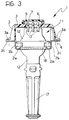
- the drawings show, by way of example, an ignition unit according to the invention for a four-cylinder internal combustion engine.
- the unit generally indicated 1, includes a casing formed by a channel-shaped support element 2 made of metal and by a cover 3 of electrically-insulating material connected to the support element 2.
- the channel-shaped element 2 has a substantially flat base wall 2a and two side walls or panels each of which has a portion 2b which is perpendicular to the base wall and a portion 2c which is bent so as to be horizontal and coplanar with the corresponding portion of the other side wall of the shaped element.
- the cover 3 is substantially tank-shaped and its longitudinal side walls have respective coplanar flanges 3a which bear on the portions 2c of the side walls of the channel-shaped element 2.
- the end walls of the cover 3 have respective extensions, indicated 3b in Figure 1, which close the ends of the channel-shaped element 2.
- the channel-shaped element 2 and the cover 3 are interconnected by rivets 4 which, in the embodiment illustrated, are constituted by tubular elements which are integral with the appendages or flanges 2c of the channel-shaped element 2 and extend through corresponding holes in the flanges 3a of the cover 3 and are then clenched onto the flanges.
- the top wall of the cover 3 has four holes 5 surrounded by respective collars 6 for retaining corresponding removable closure elements 7.
- This appendage may be formed as a separate part, as shown in Figure 7, having appendages or pins 8a which can be upset ultrasonically to fix it to the cover 3.
- a plurality of electrical terminals for example, of the flat pin type, which are not visible in the drawings but are of known type, extend in the connector appendage 8 of the cover 3.
- these terminals are integral with or at any rate connected to conductors 9 which are incorporated in the top wall of the cover 3 and have projecting ends (indicated 9a in Figures 1 and 2) which extend through the holes 5 in the cover.
- the base wall 2a of the channel-shaped element 2 has four holes, indicated 10 in Figure 2.
- Each coil is substantially of the type described in British patent application GB-A-2 231 729 in the name of the present Applicant.
- Each coil includes, in known manner, an insulating casing 12, which houses the primary and secondary windings of an ignition transformer and from which input terminals 13 and an output terminal 14 (only one of which is shown in broken outline in Figure 2) extend at opposite ends.
- Each ignition coil 11 includes a magnetic core constituted by a pack of plates 15 which extend substantially around the casing 12.
- Each coil 11 and, in particular, its pack of plates 15 is wider than each hole 10 in the base wall of the channel-shaped element 2.
- Each coil 11 is thus positioned with most of its casing 12 between the channel-shaped element 2 and the cover 3 but with part of its casing extending downwardly through a hole 10 in the channel-shaped element 2.
- the channel-shaped support element 2 Adjacent each hole 10, the channel-shaped support element 2 has integral fixing appendages 16 which are turned over onto the pack of plates 15 of the associated ignition coil 11 (see in particular Figures 1 and 2).
- the ignition coils 11 are of the so-called plug-top type and are intended to be fitted directly onto respective spark plugs of the internal combustion engine. Accordingly, as described in British patent application GB-A-2 231 729, electrical connecting elements are connected to the output terminal 14 of each coil and are housed in a flexible tubular appendage 17 of electrically insulating material, such as an elastomeric material, connected to the portion of the casing 12 of the coil 11 which projects from the channel-shaped element 2.
- the flexible tubular appendages 17 of the coils 11 are intended to be fitted in corresponding recesses in the internal combustion engine and their distal ends are intended to fit onto the ends of the corresponding plugs the central electrodes of which are thus connected to the output terminals 14 of the associated ignition coils 11.
- each coil 11 The input terminals 13 of each coil 11 are bent upwardly and are welded in order, for example by resistance welding, to the corresponding ends 9a of the conductors 9 which are incorporated in the top wall of the cover 3.
- the connector 8 is connected to the outputs of an ignition control unit which can drive the ignition coils 11 selectively by means of the conductors incorporated in the cover 3.
- the base wall 2a of the channel-shaped element 2 conveniently has further holes, indicated 18 in Figure 2, for the passage of members of the internal combustion engine.
- the flanges 2c of the channel-shaped element 2 have holes 4a in which the members for fixing the ignition unit to the internal combustion engine can be inserted.
- the ignition coils 11 and their associated connecting appendages 17 are conveniently produced as preassembled units.
- the entire unit described above can thus be assembled extremely quickly, easily, and above all, completely automatically, for example by means of electronically-controlled assembly machines.
- the assembly involves first of all the positioning of the coils 11 in the holes in the base wall of the channel-shaped support element 2 and the turning-over of the appendages 16 of the channel-shaped element to anchor the coils 11 and the cover 3 and the channel-shaped support element 2 are then riveted together.
- the input terminals 13 of the coils 11 can be welded to the corresponding ends 9a of the conductors carried by the cover 3 through the holes 5 in the top wall of the cover 3. Upon completion of the welding, the holes in the top of the cover 3 are closed by the fitting of the removable closure elements or plugs 7.
- the extremely simple structure of the ignition unit described above also facilitates operations, when the need arises, to check the functioning of the ignition coils after a certain period of use.
- the channel-shaped element 2 and the conductors 9 of the cover together form a screen against radio interference generated by the coils in operation.
- the conductors carried by the cover 3 are constituted by metal members incorporated in its top wall.
- the conductors could be constituted by pre-blanked and bent metal elements fitted on the underside of the top wall of the cover 3 and retained thereon by conventional retaining members such as engagement teeth or appendages integral with the wall which are upset over the conductor members, etc.
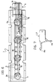
- Figure 4 shows in plan, by way of example, a conductor structure formed by blanking for incorporation (co-moulding) in the cover 3.
- the structure includes the conductors 9 with respective appendages 9a for connection to the coils and ends 9b which are intended to extend through the connector 8 shown in Figures 2 and 7.
- the structure shown in Figure 4 also has bridges 9c which connect the various conductors 9 and hold the structure together until it has been incorporated in the cover 3, after which the bridges are removed so that the conductors 9 are electrically separated.
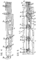
- Figure 5 is a transparent view of the cover 3 from above showing the conductor structure 9 incorporated therein.
- Figure 5 shows the terminals 9a and 9b of the conductors 9 and the bridges 9c which are accessible through the holes 5 and 5a from both sides of the cover 3 so that the bridges can be cut off and removed.
- the terminals 9a are shown in broken outline in their initial positions, in which they are coplanar with the conductors 9; after the conductor structure has been incorporated in the cover, the terminals 9a are bent so as to be substantially parallel to the axes of the holes 5 for subsequent connection to the terminals of the coils.
- Figure 6 shows an embodiment of the cover 3 in which a conductor structure similar to that shown in Figure 4 is anchored by the upsetting (for example, by ultrasound) of pins or appendages which are integral with the cover and are inserted through corresponding holes in the conductors 9.
- the upset appendages are indicated 3g in Figure 6.
- the invention is not limited to the number and arrangement of coils shown in the drawings but these may differ according to the number of cylinders in the combustion engine for which the ignition unit is intended.
Landscapes
- Engineering & Computer Science (AREA)
- Chemical & Material Sciences (AREA)
- Combustion & Propulsion (AREA)
- Mechanical Engineering (AREA)
- General Engineering & Computer Science (AREA)
- Power Engineering (AREA)
- Ignition Installations For Internal Combustion Engines (AREA)
Applications Claiming Priority (2)
| Application Number | Priority Date | Filing Date | Title |
|---|---|---|---|
| ITTO910328A IT1246068B (it) | 1991-05-03 | 1991-05-03 | Gruppo di accensione a bobine di tipo plug-top per un motore a combustione interna |
| ITTO910328 | 1991-05-03 |
Publications (3)
| Publication Number | Publication Date |
|---|---|
| EP0512357A2 true EP0512357A2 (fr) | 1992-11-11 |
| EP0512357A3 EP0512357A3 (en) | 1992-12-09 |
| EP0512357B1 EP0512357B1 (fr) | 1996-07-03 |
Family
ID=11409324
Family Applications (1)
| Application Number | Title | Priority Date | Filing Date |
|---|---|---|---|
| EP92107180A Expired - Lifetime EP0512357B1 (fr) | 1991-05-03 | 1992-04-28 | Bobine d'allumage placée sur le haut d'une bougie pour un moteur à combustion interne |
Country Status (4)
| Country | Link |
|---|---|
| EP (1) | EP0512357B1 (fr) |
| DE (1) | DE69211908T2 (fr) |
| ES (1) | ES2089278T3 (fr) |
| IT (1) | IT1246068B (fr) |
Cited By (13)
| Publication number | Priority date | Publication date | Assignee | Title |
|---|---|---|---|---|
| DE4305684A1 (en) * | 1992-02-26 | 1993-09-02 | Yazaki Corp | Electrical cabling e.g. for IC engine ignition coil and fuel injection valve - includes cylinder-head mounted coil or injectors with socket units mating with distribution network on cylinder head cover |
| DE4223071C1 (de) * | 1992-07-14 | 1993-12-23 | Audi Ag | Zündkerzen-/Zündkerzenstecker-Einheit |
| DE4405989A1 (de) * | 1994-02-24 | 1995-08-31 | Opel Adam Ag | Zündeinheit für Ottomotoren |
| US5501205A (en) * | 1994-06-10 | 1996-03-26 | Robert Bosch Gmbh | Ignition coil set for a multicylinder internal combustion engine |
| DE19620454A1 (de) * | 1995-05-25 | 1996-11-28 | Mitsubishi Electric Corp | Zündvorrichtung für eine Brennkraftmaschine |
| FR2737054A1 (fr) * | 1995-07-21 | 1997-01-24 | Renault | Dispositif de protection pour cables d'allumage haute-tension de moteur a combustion interne multicylindre a allumage commande |
| DE29621692U1 (de) * | 1996-12-13 | 1997-02-06 | Grote & Hartmann Gmbh & Co Kg, 42369 Wuppertal | Kontaktierungsvorrichtung für Einzelfunken-Zündspulen |
| WO1997029280A1 (fr) * | 1996-02-06 | 1997-08-14 | Robert Bosch Gmbh | Dispositif d'allumage pour moteur a combustion interne multicylindre |
| EP0855771A1 (fr) * | 1997-01-25 | 1998-07-29 | TEMIC TELEFUNKEN microelectronic GmbH | Rail d'allumage à connections étanches, mobiles |
| FR2775318A1 (fr) * | 1998-02-26 | 1999-08-27 | Sagem | Module d'injection multi-points pour moteur a combustion interne |
| US7350488B2 (en) * | 2006-01-20 | 2008-04-01 | Harbert Richard H | Rocker arm cover |
| US9903311B1 (en) | 2016-10-06 | 2018-02-27 | Ford Global Technologies, Llc | Engine cam cover with integrated wiring and quick-connect electrical components |
| CN108506139A (zh) * | 2017-02-24 | 2018-09-07 | 本田技研工业株式会社 | 车辆用内燃机 |
Family Cites Families (3)
| Publication number | Priority date | Publication date | Assignee | Title |
|---|---|---|---|---|
| SE437286B (sv) * | 1982-07-09 | 1985-02-18 | Saab Scania Ab | Tendsystem for flercylindrig fyrtaktmotor |
| US4706639A (en) * | 1986-12-04 | 1987-11-17 | General Motors Corporation | Integrated direct ignition module |
| FR2630782B1 (fr) * | 1988-04-28 | 1993-05-14 | Marchal Equip Auto | Bobine d'allumage pour l'allumage des moteurs a combustion interne de vehicules automobiles, et son procede de fabrication |
-
1991
- 1991-05-03 IT ITTO910328A patent/IT1246068B/it active IP Right Grant
-
1992
- 1992-04-28 EP EP92107180A patent/EP0512357B1/fr not_active Expired - Lifetime
- 1992-04-28 ES ES92107180T patent/ES2089278T3/es not_active Expired - Lifetime
- 1992-04-28 DE DE69211908T patent/DE69211908T2/de not_active Expired - Fee Related
Cited By (22)
| Publication number | Priority date | Publication date | Assignee | Title |
|---|---|---|---|---|
| DE4305684C2 (de) * | 1992-02-26 | 1998-03-26 | Yazaki Corp | Elektrische Verdrahtungsvorrichtung für einen Brennkraftmotor |
| US5390648A (en) * | 1992-02-26 | 1995-02-21 | Yazaki Corporation | Electrically wiring parts mounted on an engine |
| DE4305684A1 (en) * | 1992-02-26 | 1993-09-02 | Yazaki Corp | Electrical cabling e.g. for IC engine ignition coil and fuel injection valve - includes cylinder-head mounted coil or injectors with socket units mating with distribution network on cylinder head cover |
| DE4223071C1 (de) * | 1992-07-14 | 1993-12-23 | Audi Ag | Zündkerzen-/Zündkerzenstecker-Einheit |
| DE4405989A1 (de) * | 1994-02-24 | 1995-08-31 | Opel Adam Ag | Zündeinheit für Ottomotoren |
| DE4405989C2 (de) * | 1994-02-24 | 2000-07-06 | Opel Adam Ag | Zündeinheit für Ottomotoren |
| US5501205A (en) * | 1994-06-10 | 1996-03-26 | Robert Bosch Gmbh | Ignition coil set for a multicylinder internal combustion engine |
| DE19620454A1 (de) * | 1995-05-25 | 1996-11-28 | Mitsubishi Electric Corp | Zündvorrichtung für eine Brennkraftmaschine |
| DE19620454C2 (de) * | 1995-05-25 | 1999-06-17 | Mitsubishi Electric Corp | Zündvorrichtung für eine Brennkraftmaschine |
| FR2737054A1 (fr) * | 1995-07-21 | 1997-01-24 | Renault | Dispositif de protection pour cables d'allumage haute-tension de moteur a combustion interne multicylindre a allumage commande |
| WO1997029280A1 (fr) * | 1996-02-06 | 1997-08-14 | Robert Bosch Gmbh | Dispositif d'allumage pour moteur a combustion interne multicylindre |
| US5890473A (en) * | 1996-02-06 | 1999-04-06 | Robert Bosch Gmbh | Ignition device for a multi-cylinder internal combustion engine |
| DE29621692U1 (de) * | 1996-12-13 | 1997-02-06 | Grote & Hartmann Gmbh & Co Kg, 42369 Wuppertal | Kontaktierungsvorrichtung für Einzelfunken-Zündspulen |
| EP0855771A1 (fr) * | 1997-01-25 | 1998-07-29 | TEMIC TELEFUNKEN microelectronic GmbH | Rail d'allumage à connections étanches, mobiles |
| US5979422A (en) * | 1997-01-25 | 1999-11-09 | Temic Telefunken Microelectronic Gmbh | Ignition rail with sealed movable connections |
| WO1999043940A1 (fr) * | 1998-02-26 | 1999-09-02 | Sagem S.A. | Module d'injection multi-points pour moteur a combustion interne |
| FR2775318A1 (fr) * | 1998-02-26 | 1999-08-27 | Sagem | Module d'injection multi-points pour moteur a combustion interne |
| US7350488B2 (en) * | 2006-01-20 | 2008-04-01 | Harbert Richard H | Rocker arm cover |
| US9903311B1 (en) | 2016-10-06 | 2018-02-27 | Ford Global Technologies, Llc | Engine cam cover with integrated wiring and quick-connect electrical components |
| CN107917015A (zh) * | 2016-10-06 | 2018-04-17 | 福特环球技术公司 | 具有集成接线和快速连接电气组件的发动机凸轮罩 |
| CN107917015B (zh) * | 2016-10-06 | 2021-07-16 | 福特环球技术公司 | 具有集成接线和快速连接电气组件的发动机凸轮罩 |
| CN108506139A (zh) * | 2017-02-24 | 2018-09-07 | 本田技研工业株式会社 | 车辆用内燃机 |
Also Published As
| Publication number | Publication date |
|---|---|
| DE69211908D1 (de) | 1996-08-08 |
| EP0512357B1 (fr) | 1996-07-03 |
| ITTO910328A1 (it) | 1992-11-03 |
| DE69211908T2 (de) | 1997-01-30 |
| IT1246068B (it) | 1994-11-07 |
| ES2089278T3 (es) | 1996-10-01 |
| ITTO910328A0 (it) | 1991-05-03 |
| EP0512357A3 (en) | 1992-12-09 |
Similar Documents
| Publication | Publication Date | Title |
|---|---|---|
| EP0512357A2 (fr) | Bobine d'allumage placée sur le haut d'une bougie pour un moteur à combustion interne | |
| EP0372736B1 (fr) | Contacts électriques | |
| US4032215A (en) | Electrical contact for wire and pin with common stop | |
| KR100683986B1 (ko) | 마이카 보드 전기 저항선 가열기, 부분 조립체 부품, 및조립체 제조방법 | |
| KR100771717B1 (ko) | 히터 어셈블리용 개선된 절연체 지지부 | |
| EP0684756A2 (fr) | Socle comportant un composant électrique auxiliaire | |
| US4452869A (en) | Battery with improved terminal structure | |
| JPH0246602A (ja) | ランプ | |
| JPS6047406A (ja) | 内燃機関用点火装置 | |
| US4439751A (en) | Direct current electromagnet | |
| JPH0955237A (ja) | 圧着端子の接続装置 | |
| JP3674088B2 (ja) | 電磁機器 | |
| JPH0542625Y2 (fr) | ||
| JP2747859B2 (ja) | 照明器具用バッフルの製造方法 | |
| JPS6234426Y2 (fr) | ||
| JPH0374069A (ja) | ヒューズ付電気プラグ | |
| US4040706A (en) | Contact strip | |
| JPS581529B2 (ja) | 放電灯用安定器の製造方法 | |
| JPS5810340Y2 (ja) | トランス | |
| JPS6025878Y2 (ja) | 内燃機関用点火装置 | |
| JPH0119344Y2 (fr) | ||
| JPS6141212Y2 (fr) | ||
| JPH0132336Y2 (fr) | ||
| JPH0869927A (ja) | トランス | |
| JPH07712Y2 (ja) | エンジンの点火コイル |
Legal Events
| Date | Code | Title | Description |
|---|---|---|---|
| PUAI | Public reference made under article 153(3) epc to a published international application that has entered the european phase |
Free format text: ORIGINAL CODE: 0009012 |
|
| PUAL | Search report despatched |
Free format text: ORIGINAL CODE: 0009013 |
|
| AK | Designated contracting states |
Kind code of ref document: A2 Designated state(s): DE ES FR GB SE |
|
| AK | Designated contracting states |
Kind code of ref document: A3 Designated state(s): DE ES FR GB SE |
|
| 17P | Request for examination filed |
Effective date: 19930310 |
|
| 17Q | First examination report despatched |
Effective date: 19940906 |
|
| RAP1 | Party data changed (applicant data changed or rights of an application transferred) |
Owner name: COOPER INDUSTRIES ITALIA S.P.A. |
|
| GRAA | (expected) grant |
Free format text: ORIGINAL CODE: 0009210 |
|
| AK | Designated contracting states |
Kind code of ref document: B1 Designated state(s): DE ES FR GB SE |
|
| REF | Corresponds to: |
Ref document number: 69211908 Country of ref document: DE Date of ref document: 19960808 |
|
| REG | Reference to a national code |
Ref country code: ES Ref legal event code: FG2A Ref document number: 2089278 Country of ref document: ES Kind code of ref document: T3 |
|
| ET | Fr: translation filed | ||
| REG | Reference to a national code |
Ref country code: ES Ref legal event code: FG2A Ref document number: 2089278 Country of ref document: ES Kind code of ref document: T3 |
|
| PLBE | No opposition filed within time limit |
Free format text: ORIGINAL CODE: 0009261 |
|
| STAA | Information on the status of an ep patent application or granted ep patent |
Free format text: STATUS: NO OPPOSITION FILED WITHIN TIME LIMIT |
|
| 26N | No opposition filed | ||
| PGFP | Annual fee paid to national office [announced via postgrant information from national office to epo] |
Ref country code: GB Payment date: 20000317 Year of fee payment: 9 |
|
| PGFP | Annual fee paid to national office [announced via postgrant information from national office to epo] |
Ref country code: SE Payment date: 20000405 Year of fee payment: 9 Ref country code: FR Payment date: 20000405 Year of fee payment: 9 |
|
| PGFP | Annual fee paid to national office [announced via postgrant information from national office to epo] |
Ref country code: ES Payment date: 20000411 Year of fee payment: 9 |
|
| PGFP | Annual fee paid to national office [announced via postgrant information from national office to epo] |
Ref country code: DE Payment date: 20000427 Year of fee payment: 9 |
|
| PG25 | Lapsed in a contracting state [announced via postgrant information from national office to epo] |
Ref country code: GB Free format text: LAPSE BECAUSE OF NON-PAYMENT OF DUE FEES Effective date: 20010428 |
|
| PG25 | Lapsed in a contracting state [announced via postgrant information from national office to epo] |
Ref country code: SE Free format text: LAPSE BECAUSE OF NON-PAYMENT OF DUE FEES Effective date: 20010429 Ref country code: ES Free format text: LAPSE BECAUSE OF NON-PAYMENT OF DUE FEES Effective date: 20010429 |
|
| PG25 | Lapsed in a contracting state [announced via postgrant information from national office to epo] |
Ref country code: FR Free format text: THE PATENT HAS BEEN ANNULLED BY A DECISION OF A NATIONAL AUTHORITY Effective date: 20010430 |
|
| EUG | Se: european patent has lapsed |
Ref document number: 92107180.9 |
|
| GBPC | Gb: european patent ceased through non-payment of renewal fee |
Effective date: 20010428 |
|
| PG25 | Lapsed in a contracting state [announced via postgrant information from national office to epo] |
Ref country code: DE Free format text: LAPSE BECAUSE OF NON-PAYMENT OF DUE FEES Effective date: 20020201 |
|
| REG | Reference to a national code |
Ref country code: FR Ref legal event code: ST |
|
| REG | Reference to a national code |
Ref country code: ES Ref legal event code: FD2A Effective date: 20020514 |