EP0512541A2 - Appareil pour commander un laser semi-conducteur afin de déterminer la longévité d'un laser semi-conducteur en détectant l'augmentation de courant du laser semi-conducteur à partir de l'état initial de celui-ci - Google Patents
Appareil pour commander un laser semi-conducteur afin de déterminer la longévité d'un laser semi-conducteur en détectant l'augmentation de courant du laser semi-conducteur à partir de l'état initial de celui-ci Download PDFInfo
- Publication number
- EP0512541A2 EP0512541A2 EP92107707A EP92107707A EP0512541A2 EP 0512541 A2 EP0512541 A2 EP 0512541A2 EP 92107707 A EP92107707 A EP 92107707A EP 92107707 A EP92107707 A EP 92107707A EP 0512541 A2 EP0512541 A2 EP 0512541A2
- Authority
- EP
- European Patent Office
- Prior art keywords
- semiconductor laser
- drive current
- control apparatus
- lighting
- laser control
- Prior art date
- Legal status (The legal status is an assumption and is not a legal conclusion. Google has not performed a legal analysis and makes no representation as to the accuracy of the status listed.)
- Granted
Links
Images


Classifications
-
- H—ELECTRICITY
- H01—ELECTRIC ELEMENTS
- H01S—DEVICES USING THE PROCESS OF LIGHT AMPLIFICATION BY STIMULATED EMISSION OF RADIATION [LASER] TO AMPLIFY OR GENERATE LIGHT; DEVICES USING STIMULATED EMISSION OF ELECTROMAGNETIC RADIATION IN WAVE RANGES OTHER THAN OPTICAL
- H01S5/00—Semiconductor lasers
- H01S5/06—Arrangements for controlling the laser output parameters, e.g. by operating on the active medium
-
- H—ELECTRICITY
- H01—ELECTRIC ELEMENTS
- H01S—DEVICES USING THE PROCESS OF LIGHT AMPLIFICATION BY STIMULATED EMISSION OF RADIATION [LASER] TO AMPLIFY OR GENERATE LIGHT; DEVICES USING STIMULATED EMISSION OF ELECTROMAGNETIC RADIATION IN WAVE RANGES OTHER THAN OPTICAL
- H01S5/00—Semiconductor lasers
- H01S5/0014—Measuring characteristics or properties thereof
- H01S5/0021—Degradation or life time measurements
-
- H—ELECTRICITY
- H01—ELECTRIC ELEMENTS
- H01S—DEVICES USING THE PROCESS OF LIGHT AMPLIFICATION BY STIMULATED EMISSION OF RADIATION [LASER] TO AMPLIFY OR GENERATE LIGHT; DEVICES USING STIMULATED EMISSION OF ELECTROMAGNETIC RADIATION IN WAVE RANGES OTHER THAN OPTICAL
- H01S5/00—Semiconductor lasers
- H01S5/06—Arrangements for controlling the laser output parameters, e.g. by operating on the active medium
- H01S5/068—Stabilisation of laser output parameters
- H01S5/06825—Protecting the laser, e.g. during switch-on/off, detection of malfunctioning or degradation
-
- H—ELECTRICITY
- H01—ELECTRIC ELEMENTS
- H01S—DEVICES USING THE PROCESS OF LIGHT AMPLIFICATION BY STIMULATED EMISSION OF RADIATION [LASER] TO AMPLIFY OR GENERATE LIGHT; DEVICES USING STIMULATED EMISSION OF ELECTROMAGNETIC RADIATION IN WAVE RANGES OTHER THAN OPTICAL
- H01S5/00—Semiconductor lasers
- H01S5/06—Arrangements for controlling the laser output parameters, e.g. by operating on the active medium
- H01S5/0617—Arrangements for controlling the laser output parameters, e.g. by operating on the active medium using memorised or pre-programmed laser characteristics
-
- H—ELECTRICITY
- H01—ELECTRIC ELEMENTS
- H01S—DEVICES USING THE PROCESS OF LIGHT AMPLIFICATION BY STIMULATED EMISSION OF RADIATION [LASER] TO AMPLIFY OR GENERATE LIGHT; DEVICES USING STIMULATED EMISSION OF ELECTROMAGNETIC RADIATION IN WAVE RANGES OTHER THAN OPTICAL
- H01S5/00—Semiconductor lasers
- H01S5/06—Arrangements for controlling the laser output parameters, e.g. by operating on the active medium
- H01S5/068—Stabilisation of laser output parameters
- H01S5/06804—Stabilisation of laser output parameters by monitoring an external parameter, e.g. temperature
-
- H—ELECTRICITY
- H01—ELECTRIC ELEMENTS
- H01S—DEVICES USING THE PROCESS OF LIGHT AMPLIFICATION BY STIMULATED EMISSION OF RADIATION [LASER] TO AMPLIFY OR GENERATE LIGHT; DEVICES USING STIMULATED EMISSION OF ELECTROMAGNETIC RADIATION IN WAVE RANGES OTHER THAN OPTICAL
- H01S5/00—Semiconductor lasers
- H01S5/06—Arrangements for controlling the laser output parameters, e.g. by operating on the active medium
- H01S5/068—Stabilisation of laser output parameters
- H01S5/06808—Stabilisation of laser output parameters by monitoring the electrical laser parameters, e.g. voltage or current
-
- H—ELECTRICITY
- H01—ELECTRIC ELEMENTS
- H01S—DEVICES USING THE PROCESS OF LIGHT AMPLIFICATION BY STIMULATED EMISSION OF RADIATION [LASER] TO AMPLIFY OR GENERATE LIGHT; DEVICES USING STIMULATED EMISSION OF ELECTROMAGNETIC RADIATION IN WAVE RANGES OTHER THAN OPTICAL
- H01S5/00—Semiconductor lasers
- H01S5/06—Arrangements for controlling the laser output parameters, e.g. by operating on the active medium
- H01S5/068—Stabilisation of laser output parameters
- H01S5/0683—Stabilisation of laser output parameters by monitoring the optical output parameters
Definitions
- the present invention relates to a semiconductor laser control apparatus, more particularly, to a semiconductor laser control apparatus for confirming the service life of a semiconductor laser by detecting the current increase of the semiconductor laser from an initial state thereof.
- POS point-of-sale
- Semiconductor lasers have mainly been used for POS systems rather than gas lasers.
- the service life of a semiconductor laser is relatively short, and when the POS system becomes in operatable because of expiration of the service life, the work using the POS system stops working.
- the service life of the semiconductor laser is very dispersive in the individual semiconductor laser, and further the service life of the semiconductor laser is also dispersive by the circumstances (especially, temperature) of the POS system using the semiconductor laser.
- the service life of a semiconductor laser is, for example, 4000 - 7000 hours under continuous operation at 50 ° C, but the service life of the same semiconductor laser is, for example, two times (8000 - 14000) hours under continuous operation at 40 ° C.
- the service life of the semiconductor laser is very dispersive in the individual semiconductor laser and the temperature of the POS system using the semiconductor laser.
- An object of the present invention is to provide a semiconductor laser control apparatus that allows replacement of the semiconductor laser at an appropriate time before failure of operation by predicting the expiration of the service life of the semiconductor laser.
- a semiconductor laser control apparatus comprising: a semiconductor laser; a semiconductor laser control circuit for controlling a drive current of the semiconductor laser to output a specific light quantity from the semiconductor laser; a drive current measuring unit for measuring a drive current of the semiconductor laser; a memory unit for storing at least one initial drive current values of the semiconductor laser for the specific light quantity and corresponding temperatures of the initial drive current values; a detection unit for comparing an actual drive current value of the semiconductor laser measured by the drive current measuring unit with the initial drive current value corresponding to an actual temperature when the actual drive current is measured; and a warning unit for generating an alarm of a prediction of the expiration of service life of the semiconductor laser, when the actual drive current value exceeds the corresponding initial drive current value as much as a specified percentage.
- the semiconductor laser control apparatus may further comprise a temperature measuring unit for measuring a temperature of the semiconductor laser.
- the memory unit may store a plurality of initial drive current values of the semiconductor laser and corresponding temperatures of each of the initial drive current values.
- the memory unit may store one initial drive current value of the semiconductor laser and a corresponding temperature of the initial drive current values. Further, the memory unit may be constituted by an EEPROM or EPROM.
- the semiconductor laser and the memory unit may be provided in the same package.
- the detection unit may include: a first drive unit for controlling the lighting with a first light quantity; and a second drive unit for controlling the lighting with a second light quantity less than the first light quantity, and switches over the first drive unit to the second drive unit, when the actual drive current value is increased by a specified percentage over the corresponding initial current value while the lighting is controlled by the first drive unit.
- the semiconductor laser control apparatus may repeat switching ON and OFF of the semiconductor laser at a specified ratio, continuously remain on when a specified information is detected in a reflection light from an object to be radiated and repeats lighting and extinguishing at the specified ratio when the following information is not detected even after a first time being passed from an information detection timing, and the time setting is changed from the first time to a second time shorter than the first time when the drive current value is increased by a specified percentage over the initial drive current value at the corresponding temperature.
- a semiconductor laser control apparatus repeating lighting and extinguishing of a semiconductor laser at a specified ratio, continuously remaining on when a specified information is detected in a reflection light from an object to be radiated, and repeating lighting and extinguishing at the specified ratio when the following information is not detected even after the specified time has passed from the information detection timing
- the semiconductor laser control apparatus comprises: a first drive unit for controlling the lighting of the semiconductor laser with a first light quantity; a second drive unit for controlling the lighting of the semiconductor laser with a second light quantity larger than the first light quantity; and a control unit for controlling the lighting by the first drive unit in continuous lighting and changing over to the second drive unit in repetition of lighting and extinguishing.
- a bar code reader device for reading the data of a bar code label and supplying the data to a point-of-sale terminal, having a semiconductor laser control apparatus, wherein the semiconductor laser control apparatus comprises: a semiconductor laser; a semiconductor laser control circuit for controlling a drive current of the semiconductor laser to output a specific light quantity from the semiconductor laser; a drive current measuring unit for measuring a drive current of the semiconductor laser; a memory unit for storing at least one initial drive current values of the semiconductor laser for the specific light quantity and corresponding temperatures of the initial drive current values; a detection unit for comparing an actual drive current value of the semiconductor laser measured by the drive current measuring unit with the initial drive current value corresponding to an actual temperature when the actual drive current is measured; and a warning unit for generating an alarm of a prediction of the expiration of service life of the semiconductor laser, when the actual drive current value exceeds the corresponding initial drive current value as much as a specified percentage.
- a bar code reader device for reading the data of a bar code label and supplying the data to a point-of-sale terminal, having a semiconductor laser control apparatus repeating lighting and extinguishing of a semiconductor laser at a specified ratio, continuously remaining on when a specified information is detected in a reflection light from an object to be radiated, and repeating lighting and extinguishing at the specified ratio when the following information is not detected even after the specified time has passed from the information detection timing
- the semiconductor laser control apparatus comprises: a first drive unit for controlling the lighting of the semiconductor laser with a first light quantity; a second drive unit for controlling the lighting of the semiconductor laser with a second light quantity larger than the first light quantity; and a control unit for controlling the lighting by the first drive unit in continuous lighting and changing over to the second drive unit in repetition of lighting and extinguishing.
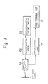
- Figure 1 shows an example of a bar code reader device using the semiconductor laser control apparatus.
- reference numeral 100 denotes a POS terminal unit
- 102 denotes a semiconductor laser
- 103 denotes a semiconduztor laser control circuit
- 104 denotes an optical unit
- 105 denotes a demodulation unit.
- data of a bar code label is detected by the optical unit 104 and supplied to the POS terminal unit 100 through the demodulation unit 105.
- an emitted light output from the semiconductor laser 102 is applied to the optical unit and used to read the data of the bar code label, and the semiconductor laser 102 is controlled by the semiconductor laser control circuit 103.
- a light quantity of the semiconductor laser 102 is controlled by adjusting a laser drive current in the semiconductor laser control circuit 103, so that a specific light quantity is output from the semiconductor laser 102 to the optical unit 104.
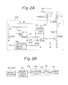
- Figures 2A and 2B show an example of a semiconductor laser control apparatus according to the prior art.
- the semiconductor laser 102 comprises a laser diode (LD) 102b and a photo diode (PD) 102a, and a drive current If of the laser diode 102b is controlled by a current 1m of the photo diode 102a, corresponding to the light quantity of the laser diode 102b which is detected by the photo diode 102a, to maintain the light quantity of the semiconductor laser 102 at a fixed level.
- LD laser diode
- PD photo diode
- the current 1m is converted to a voltage by a resistor R130 and amplified by an operation amplifier A131, and then divided to a voltage VA corresponding to the specified light quantity by a variable resistor VR132.
- the voltage VA is compared with a reference voltage Vref generated from a voltage adjust circuit 118, resistors R137 and R138, and integrated by an operation amplifier A134. Further, the voltage VA after integration by the operation amplifier A134 is converted to the laser drive current If by the transistor TR136.
- a reference numeral 117 denotes an analog switch (ANSW)
- C133 denotes a capacitor connected in parallel to the analog switch 117.
- reference numeral 115 denotes an image sensor provided in the optical unit 104
- 116 denotes a binary-coding circuit
- 106 denotes a detector
- 109 denotes a central processing unit (CPU)
- 114 denotes a timer.
- the demodulation unit 105 includes the detector 106 and the CPU 109, and a switching control signal AA is output from the CPU 109 to the analog switch 117.
- the analog switch 117 is controlled in accordance with the switching control signal AA output from the CPU 109.
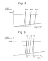
- Figure 3 shows an example of emission characteristics of a semiconductor laser.
- the light quantity is controlled to be fixed by the above control even though the temperature characteristic or the like varies.
- the light quantity of the semiconductor laser is set by the variable resistor VR132, so that the light quantity becomes the specified value.
- the analog switch (ANSW) 117 is used to turn OFF the semiconductor laser 102 and to reduce the lighting time of the semiconductor laser 102 during operation by controlling ON/OFF operation of the analog switch 117.
- the configuration of this semiconductor laser control apparatus is proposed by some inventors including the same inventors (the same applicant, or asignee) of this application under Japanese Patent Application No. 02-314606 (which corresponds to U.S. Patent Application No. 07/794,226).
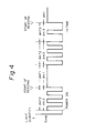
- Figure 4 is a timing chart for explaining a laser control operation in the semiconductor laser control apparatus according to the prior art.
- a first mode dm1 for continuous lighting second mode dm2 for repetitive lighting and extinguishing, and third mode dm3 for repetitive lighting and extinguishing with a lower lighting ratio than that of the second mode dm2 are set.
- Fig. 4 according to the proposal disclosed in JPP'606, a first mode dm1 for continuous lighting, second mode dm2 for repetitive lighting and extinguishing, and third mode dm3 for repetitive lighting and extinguishing with a lower lighting ratio than that of the second mode dm2 are set. Namely, in Fig.
- the lighting mode is set to the first mode dm1 when a scan of the bar code label is detected (detection of the start of reading), the second mode dm2 when a next scan is not detected even after lapse of the specified time dmT1 in the first mode dm1, and the third mode dm3 when a scan is not detected even after lapse of the specified time dmT2 in the second mode md2.
- the laser beam scans the same bar code label by a plurality of times, and is set to the first mode mdl when the start of scan is detected in the second and third modes md2, md3. Therefore, when the system is not used, the total lighting time is reduced by automatically setting the laser system to the ready condition when the lighting ratio (period) is low.
- reflection light received by the image sensor 115 is converted to an electric signal and binary-coded by the binary-coding circuit 116.
- the CPU 109 starts the demodulation, sets the semiconductor laser 102 to the first mode md1, and sets the subsequent lighting modes while monitoring the output of the timer 114.
- the guard bar is positioned at both the start and end portion of each bar code label of the Universal Product Code (UPC) Standard. Further, in another bar code label of NW7, CODE-39, ITF, and the like, the guard bar may be called a start character, end character, and the like.
- the service life of the semiconductor laser (102) is relatively short and grately dispersive in the individual semiconductor laser and therefore it contrives to reduce the duration of lighting when the semiconductor laser is not being used during an operation as described above.
- the semiconductor laser should be replaced and the work will be hindered.
- the service life of a semiconductor laser is relatively short, and when the system using the semiconductor laser (for example, a POS system) becomes in operatable because of expiration of the service life, the work using the POS system will stop.
- the service life of the semiconductor laser is very dispersive in the individual semiconductor laser, and further the service life of the semiconductor laser is also dispersive by the circumstances (especially, temperature) of the POS system using the semiconductor laser. Therefore, it is necessary to replace the semiconductor laser by predicting the expiration of its service life before failure of operation and extend the time of operation until such inactivity.
- Figure 5 shows a principle of a semiconductor laser control apparatus according to the present invention.
- reference numeral 2 denotes a semiconductor laser
- 3 denotes a semiconductor laser control circuit
- 20 denotes a drive current measuring unit
- 21 denotes a temperature measuring unit
- 22 denotes a detection unit
- 23 denotes a warning unit
- 24 denotes a memory unit.
- the semiconductor laser control circuit 3 is used to control a drive current of the semiconductor laser 2 to output a specified light quantity from the semiconductor laser 2.
- the drive current measuring unit 20 is used to measure the drive current (actual drive current I) of the semiconductor laser 2
- the temperature measuring unit 21 is used to measure the temperature (actual temperature T) of the semiconductor laser 2.
- the detection unit 22 is used to compare the actual drive current value detected by the drive current measuring unit 20 with the initial drive current value stored in the memory unit 24 corresponding to the temperature at the actual temperature detected by the temperature measuring unit 21.
- the actual temperature (T) measured by the temperature measuring unit 21 is specified at 20 ° C
- the actual drive current (lop, If) detected by the drive current measuring unit 20 is compared with the initial drive current 40 mA at 20 ° C which is previously stored in the memory unit 24.
- the actual drive current is compared with the initial drive current 60 mA at 40 ° C previously stored in the memory unit 24.
- the warning unit 23 generates an alarm when the measured drive current value is increased by the specified percentage (for example, 20 %) over the initial drive current value of the corresponding temperature.
- the above operation is carried out a predetermined time each day (for example, at the time of switching ON the POS system), every hour, and the like.
- the memory unit 24 which is, for example, an erasable programmable read only memory (EPROM) or electrically erasable programmable read only memory (EEPROM), stores a plurality of temperature data and the initial drive currents corresponding to the temperature data. Further, as shown in Fig. 5, the initial drive current values of the semiconductor laser 2 are different in accordance with the temperature. Furthermore, even though the temperatures of a plurality of semiconductor lasers are the same, the initial drive currents of the semiconductor lasers are different from each other, since temperature-drive current characteristics are quite different in individual semiconductor lasers. Consequently, the memory unit 24 for storing the initial drive current values and corresponding temperatures must be provided for each of the individual semiconductor lasers. Further, it is preferable to replace the semiconductor laser 2 of the POS system to provide the semiconductor laser 2 and the memory unit 24 in the same package.
- EPROM erasable programmable read only memory
- EEPROM electrically erasable programmable read only memory
- the memory unit 24 can store only one initial drive current (reference drive current I ref ) and corresponding temperature (reference temperature T ref ), and another initial drive currents corresponding to another temperatures can be calculated, which will be explained with reference to Fig. 8. In this case, the accuracy of the relationships between the temperatures and the initial drive currents may be decreased, and the actual temperature of the semiconductor laser may be limited to a small range (for example, T ref ⁇ 5 ° C).
- the memory unit 24 can also store one initial drive current (reference drive current I ref ) and corresponding temperature (for example, 25*C), and a plurality of temperature compensation values (A I) and corresponding temperatures (for example, 30, 35, 40 ° C, ).
- data stored in the memory unit 24 and the calculation manner for obtaining the initial current value at the actual temperature can be modified.
- Figure 6 is an example of emission characteristics of a semiconductor laser explaining the principle of the semiconductor laser control apparatus according to the present invention.
- the drive current of the semiconductor laser 2 is necessary for the specified quantity increases in accordance with the total lighting time, that is, the semiconductor laser and the semiconductor laser 2 finally fail to operate. Nevertheless, in the present invention, the temperature-drive current characteristics are used to confirm the service life of the semiconductor laser by detecting the current increase of the semiconductor laser from the initial state thereof.
- the drive current value in the initial lighting of the semiconductor laser 2 (If in Fig. 6) at a temperature TO is measured and stored in the memory unit 24. Further, an actual drive current value and an actual temperature of the semiconductor laser during the operation state is detected (measured) in a specific time interval by the drive current measuring unit 20, the temperature measuring unit 21 and the detection unit 22, and the detected drive current value is compared with the initial drive current value stored in the memory unit 24 corresponding to the actual temperature of the semiconductor laser 2.
- the drive current value varies with the temperature of the semiconductor laser 2 and also with each of the individual semiconductor lasers 2. Therefore, as shown in Fig. 5, the initial drive current value at each temperature for each semiconductor laser 2 is measured and stored in memory unit (EPROM or EEPROM) 24 and used in combination with this semiconductor laser 2.
- the drive current measuring unit 20 and the temperature measuring unit 21 always measure, respectively, the drive current and temperature of the semiconductor laser 2, and the detection unit 22 periodically picks up the measured drive current value and temperature and compares the measured drive current value with the initial drive current value corresponding to the measured temperature.
- the warning unit 23 generates an alarm based on a prediction of the expiration of the service life of the semiconductor laser 2, when the drive current value exceeds the initial drive current value as much as the specified percentage (for example, If, shown in Fig. 6, e.g., 20 %). Note, since the semiconductor laser 2 still operates at this timing, the work will not be hindered when the semiconductor laser 2 and the memory unit 24 are replaced during an appropriate time zone.
- Figures 7A and 7B show a first embodiment of a semiconductor laser control apparatus according to the present invention.
- this first embodiment shows an example of a configuration of the semiconductor laser control apparatus which always continuously lights up, and an example of warning the expiration of service life by lamp indication.
- the semiconductor laser control circuit 3 has the same configuration with exception that the analog switch ANSW 117 in Fig. 2A (or equivalent to the OFF state of the analog switch ANSW 117) is omitted and performs the same continuous lighting control as when the analog switch ANSW 117 is switched OFF.
- the semiconductor laser 2 comprises a laser diode (LD) 2b and a photo diode (PD) 2a, and a drive current If of the laser diode 2b is controlled by a current 1m of the photo diode 2a, corresponding to the light quantity of the laser diode 2b which is detected by the photo diode 2a, to maintain the light quantity of the semiconductor laser 2 at a fixed level.
- LD laser diode
- PD photo diode
- the current 1m is converted to a voltage by a resistor R30 and amplified by an operation amplifier A31, and then divided to a voltage VA corresponding to the specified light quantity by a variable resistor VR32.
- the voltage VA is compared with a reference voltage Vref generated from a voltage adjust circuit 18, resistors R37 and R38, and integrated by an operation amplifier A34. Further, the voltage VA after integration by the operation amplifier A34 is converted to the laser drive current If by the transistor TR36.
- C33 denotes a capacitor connected between a negative input terminal and an output terminal of the operation amplifier A34.
- reference numerals 7, 8 denote analog to digital converters (ADCs)
- 9 denotes a central processing unit (CPU)
- 10 denotes an EEPROM
- 11 denotes a lamp
- 12 denotes a voltage adjust circuit
- 1 denotes a temperature sensor
- A39 denotes an operation amplifier. Comparing Figs. 5 and 7B, the operation amplifier A39 and the ADC 7 correspond to the drive current measuring unit 20, the temperature sensor 1 and the ADC 8 correspond to the temperature measuring unit 21, the CPU 9 corresponds to the detection unit 22, the lamp 11 corresponds to the warning unit 23, and the EEPROM 10 corresponds to memory unit 24.
- the ADC 7 is used to convert an output voltage of the operation amplifier A39 to a digital signal, and the converted digital signal is supplied to the CPU 9.
- the ADC 8 is used to convert a voltage of the temperature sensor 1 to a digital signal, and the converted digital signal is supplied to the CPU 9.
- the EEPROM 10 may be constituted by an EPROM.
- both ends BB and CC of the resistor R35 are connected to input terminals of the operating amplifier A39. Namely, a potential caused by the resistor R35 is applied to the operation amplifier A39 to measure the drive current If of the semiconductor laser 2.
- the EEPROM 10 stores the corresponding initial drive current value of the semiconductor laser 2 in relation to the temperature. Note, the EEPROM 10 besidesy stores a plurality of initial drive current values corresponding to various temperatures. Nevertheless, the EEPROM 10 can store only one initial drive current value of a specific temperature, and another initial drive currents corresponding to various temperatures can be calculated by using the stored initial drive current value of the specific temperature.
- the accuracy of the initial drive currents calculated by using the stored initial drive current value may decrease.
- the semiconductor laser 2 is put in advance in a thermostatic oven, which is set to respective temperatures, and a drive current (initial drive current), from which the specified light quantities can be respectively obtained, is measured.
- the CPU 9 picks up a drive current value (actual drive current value) and a temperature from the outputs of the ADC 7 and the ADC 8 at a specified time interval, and further, the CPU 9 picks up the initial drive current corresponding to the temperature from the EEPROM 10. Further, the CPU 9 compares the actual drive current value with the initial drive current corresponding to the detected temperature, and it is determined whether the actual drive current value exceeds the specified percentage (for example, 20 %) and the initial drive current value at that temperature is verified. Consequently, when it is determined that the actual drive current value exceeds the specified percentage, the initial drive current value, the lamp 11 lights up to indicate the near expiration of the service life of the semiconductor laser 2, and a new semiconductor laser and an EEPROM 10 thereof are replaced.
- a drive current value actual drive current value
- a temperature from the outputs of the ADC 7 and the ADC 8 at a specified time interval
- the CPU 9 picks up the initial drive current corresponding to the temperature from the EEPROM 10. Further, the CPU 9 compares the actual drive
- FIG. 8 is a flow chart showing an example of a laser control operation carried out in the semiconductor laser control apparatus according to the present invention.
- a reference temperature T ref for example, 25 ° C, or 35 ° C
- EEPROM EEPROM
- reference T denotes a temperature (actual temperature) of the semiconductor laser 2
- ⁇ I denotes a temperature compensation value (for example, 1 mA/° C)
- l lim (T) denotes a limit drive current of the semiconductor laser 2 at the actual temperature T.
- l lim (T) is determined to be a value 20 % larger than the initial drive current value I ref .
- Step 81 an actual temperature T of the semiconductor laser 2 is measured by the temperature sensor 1 (temperature measuring unit 21), and the flow proceeds to Step 82.
- Step 82 it is determined whether the actual temperature T of the semiconductor laser 2 is larger than a value (T ref + 5) ° C
- Step 83 it is determined whether the actual temperature T of the semiconductor laser 2 is smaller than a value (T ret - 5) ° C.
- Steps 82 and 83 when the actual temperature T of the semiconductor laser 2 is included in the temperature range from (T ret - 5) ° C to (T ref + 5) ° C, the flow proceeds to Step 84, and in the other cases, the flow returns to Step 81.
- Step 84 a limit drive current l lim (T) of the semiconductor laser 2 is calculated by the following equation (1), and then the flow proceeds to Step 85.
- l lim (T) is determined to be a value 20 % larger than the initial drive current value l ref at the actual temperature.
- Step 85 an actual drive current lop (If) is measured by the drive current measuring unit 20, and the flow proceeds to Step 86 wherein it is determined whether the limit drive current l lim (T) of the semiconductor laser 2 is larger than the actual drive current lop.
- Step 86 when it is determined that the limit drive current l lim (T) is not larger than the actual drive current lop, the flow proceeds to Step 87, and when it is determined that the limit drive current l lim (T) is larger than the actual drive current lop, the flow returns to Step 81.
- Step 87 a predetermined laser expiration operation is carried out.
- Step 87 for example, a lamp 11 lights up to indicate the near expiration of the service life of the semiconductor laser 2, or a specified message showing the service life of the semiconductor laser 2 has expired is indicated on the POS system. Consequently, a new semiconductor laser and an EEPROM thereof are replaced.
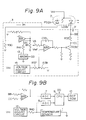
- Figures 9A and 9B show a second embodiment of a semiconductor laser control apparatus according to the present invention. Note, in the second embodiment of the present invention, the drive current is reduced to prolong the service life of the semiconductor laser 2 after the near expiration of the service life has been detected in the first embodiment shown in Figs. 7A and 7B.
- the semiconductor laser control circuit 3 shown in Fig. 9A is the same as shown in Fig. 7A except for an analog switch (ANSW) 13 and a resistor R41, which are additionally provided and carriy out the same lighting control and detection.
- the analog switch 13 and the resistor R41 are connected parallel to the variable resistor VR32, and when the analog switch 13 is switched ON, a specified light quantity is obtained.
- the CPU 9 detects the near expiration of service life of the semiconductor laser 2
- the switching control signal DD is output from the CPU 9 to the analog switch 13
- the analog switch 13 is switched OFF, and the voltage value VA is increased and the drive current If and the light quantity is reduced. Consequently, the subsequent service life of the semiconductor laser 2 can be extended.
- the drive current of the semiconductor laser 2 is decreased. Namely, though the light quantity is reduced and the operation efficiency deteriorates by the above operation, the subsequent operation time until failure of operation can be extended.
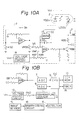
- FIGS 10A and 10B show a third embodiment of a semiconductor laser control apparatus according to the present invention, wherein a reference numeral 14 denotes a timer. Note, in the third embodiment of the present invention, the semiconductor laser control apparatus controls lighting and extinguishing operations in the second mode (dm2) and the third mode (dm3) described in the prior art, when it is not used.
- the CPU 9 sets the time (dmT1) in continuous lighting (the first mode dm1) to the first time, for example, 5 seconds, and changes the time to the second time (dmT2), that is, 2 seconds according to the timer 14, when the near expiration of service life of the semiconductor laser is detected. Therefore, the continuous lighting time is shortened, and thus the subsequent operation time until the failure of operation can be extended.
- the semiconductor laser control apparatus which repeats lighting and extinguishing operations of the semiconductor laser 2 at the specified ratio, continuously lights up the semiconductor laser 2 when the start of reading is detected, and repeats lighting and extinguishing operations at the above described ratio when the next reading is not started even after a lapse of the first time from the detection timing, the time setting is changed from the first time to a shorter second time shorter when the expiration of the service life is detected. Therefore, the continuous lighting time is reduced and the subsequent operation time until failure of operation can be extended.
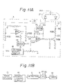
- Figures 11A and 11B show a fourth embodiment of a semiconductor laser control apparatus according to the present invention
- Fig. 12 is a timing chart for explaining a laser control operation in the semiconductor laser control apparatus of Figs. 11 A and 11 B.
- the semiconductor laser is used for lighting up a bar code label provided on each of the various goods, and the contents (information) of the bar code are read out by an image sensor which detects a reflected light (laser) from the bar code.
- the laser also shines onto the face of an operator. Note, in general, it is not preferable to shine a large amount of laser beam (laser energy) into the eyes of an operator of the POS system, and thus, a total amount of laser energy input into the eyes of the operator must be limited to a specific value to protect the operator.
- the semiconductor laser control apparatus controls lighting and extinguishing as described in the prior art example with reference to Figs. 1 to 4. Namely, as shown in Fig. 12, when a bar code label is scanned in the second mode dm2 or the third mode dm3, the detection of bar code information is delayed and the changeover to the first mode dm1 for continuous lighting may also be delayed, and therefore operation efficiency will deteriorate.
- This fourth embodiment is intended to provide an improvement in this point, and specifically, the light quantity of the semiconductor laser 2 is increased in the second mode dm2 and the third mode dm3, and the detectable range (area) is expanded. Note, in the cases of the second mode dm2 and the third mode dm3, the total amount of laser energy input into the eyes of an operator is lower than a specific value to protect the operator. Because, in the second mode dm2 and the third mode dm3, a light quantity (output power) of the semiconductor laser 2 is increased but the semiconductor laser 2 is repetitively lighted and extinguished.
- the configuration of the semiconductor laser control apparatus shown in Figs 11 A and 11B is a similar configuration of Figs. 2A and 2B, wherein a resistor R41 and an analog switch (ANSW) 13 are added.
- the variable resistor VR32 is adjusted in advance by setting the analog switch 17 to switch OFF and the analog switch 13 to switch OFF.
- the analog switch 13 is controlled by a switch control signal FF output from the CPU 9, and further, the analog switch 17 is controlled by a switch control signal GG output from the CPU 9.
- the CPU 9 controls the analog switch 13 to switch OFF in the first mode md1, and the analog switch 13 to switch ON in the second mode dm2 and the third mode dm3.
- the light quantity increases in the second mode dm2 and the third mode dm3 as shown in Figure 12 and the detection distance is extended.
- the light quantity of the semiconductor laser 2 in the third mode dm3 can be determined to be a larger value than that of the second mode dm2, since a percentage of lighting (ON state) of the semiconductor laser 2 in the third mode dm3 is lower than that of the second mode dm2.
- the fourth embodiment can apply to the third embodiment.
- a resistor (41) and an analog switch (13) can be connected parallel to the variable resistor VR32 and ON/OFF control can be carried out.
- the light quantity in repeating lighting and extinguishing operations increases and the distance along which an object (bar code label provided on an article) to be irradiated can be identified, and thus the changeover to continuous lighting is expected and the operation efficiency is improved.
- the present invention is constituted to generate an alarm by predicting the service life of the semiconductor laser and extend the time before the apparatus fails to operate by detecting the near expiration of the service life and therefore ensure the operational effects, such as replacement of the semiconductor laser, without inconveniencing operation.
- the semiconductor laser control apparatus can be provided for a bar code reader and a POS system, and also provided for various kinds of laser devices using a semiconductor laser.
Landscapes
- Physics & Mathematics (AREA)
- Condensed Matter Physics & Semiconductors (AREA)
- General Physics & Mathematics (AREA)
- Electromagnetism (AREA)
- Optics & Photonics (AREA)
- Semiconductor Lasers (AREA)
Priority Applications (1)
| Application Number | Priority Date | Filing Date | Title |
|---|---|---|---|
| EP95106697A EP0669684B1 (fr) | 1991-05-10 | 1992-05-07 | Appareil de contrôle d'un laser semi-conducteur pour confirmer la durée de service d'un laser semi-conducteur en détectant l'augmentation de courant du laser semi-conducteur à partir de l'état initial de celui-ci |
Applications Claiming Priority (2)
| Application Number | Priority Date | Filing Date | Title |
|---|---|---|---|
| JP105293/91 | 1991-05-10 | ||
| JP3105293A JP2546080B2 (ja) | 1991-05-10 | 1991-05-10 | 半導体レーザー制御装置 |
Related Child Applications (2)
| Application Number | Title | Priority Date | Filing Date |
|---|---|---|---|
| EP95106697A Division EP0669684B1 (fr) | 1991-05-10 | 1992-05-07 | Appareil de contrôle d'un laser semi-conducteur pour confirmer la durée de service d'un laser semi-conducteur en détectant l'augmentation de courant du laser semi-conducteur à partir de l'état initial de celui-ci |
| EP95106697.6 Division-Into | 1992-05-07 |
Publications (3)
| Publication Number | Publication Date |
|---|---|
| EP0512541A2 true EP0512541A2 (fr) | 1992-11-11 |
| EP0512541A3 EP0512541A3 (en) | 1993-11-18 |
| EP0512541B1 EP0512541B1 (fr) | 1996-09-18 |
Family
ID=14403644
Family Applications (2)
| Application Number | Title | Priority Date | Filing Date |
|---|---|---|---|
| EP95106697A Expired - Lifetime EP0669684B1 (fr) | 1991-05-10 | 1992-05-07 | Appareil de contrôle d'un laser semi-conducteur pour confirmer la durée de service d'un laser semi-conducteur en détectant l'augmentation de courant du laser semi-conducteur à partir de l'état initial de celui-ci |
| EP92107707A Expired - Lifetime EP0512541B1 (fr) | 1991-05-10 | 1992-05-07 | Appareil pour commander un laser semi-conducteur afin de déterminer la longévité d'un laser semi-conducteur en détectant l'augmentation de courant du laser semi-conducteur à partir de l'état initial de celui-ci |
Family Applications Before (1)
| Application Number | Title | Priority Date | Filing Date |
|---|---|---|---|
| EP95106697A Expired - Lifetime EP0669684B1 (fr) | 1991-05-10 | 1992-05-07 | Appareil de contrôle d'un laser semi-conducteur pour confirmer la durée de service d'un laser semi-conducteur en détectant l'augmentation de courant du laser semi-conducteur à partir de l'état initial de celui-ci |
Country Status (5)
| Country | Link |
|---|---|
| US (1) | US5334826A (fr) |
| EP (2) | EP0669684B1 (fr) |
| JP (1) | JP2546080B2 (fr) |
| KR (1) | KR960006211B1 (fr) |
| DE (2) | DE69213811T2 (fr) |
Cited By (11)
| Publication number | Priority date | Publication date | Assignee | Title |
|---|---|---|---|---|
| US5583683A (en) * | 1995-06-15 | 1996-12-10 | Optical Corporation Of America | Optical multiplexing device |
| DE4396839T1 (de) * | 1992-12-18 | 1997-07-31 | Olympus Optical Co | Wellenlängenstabilisierende Vorrichtung |
| EP0823759A3 (fr) * | 1996-08-06 | 1999-01-07 | Cutting Edge Optronics, Inc. | Arrangement de diodes laser intelligentes |
| WO1999040654A1 (fr) * | 1998-01-21 | 1999-08-12 | Altitun Ab | Procede pour optimiser les points d'application des lasers et systeme pour mettre en oeuvre ce procede |
| EP1069658A1 (fr) * | 1999-07-13 | 2001-01-17 | Lucent Technologies Inc. | Méthode et dispositif pour la compensation active numérique de la température d'un étalon d'un laser à longueur d'onde stabilisé |
| WO2004040722A1 (fr) * | 2002-10-30 | 2004-05-13 | Intune Technologies Limited | Procede de compensation de la degradation dans des lasers accordables |
| US6826206B1 (en) | 1999-02-17 | 2004-11-30 | Adc Telecommunications, Inc. | Method of characterizing a tuneable laser |
| EP1681750A1 (fr) * | 2005-01-17 | 2006-07-19 | Fanuc Ltd | Oscillateur Laser et méthode d'estimation de la durée de vie d'une source de pompage optique |
| US7170919B2 (en) | 2003-06-23 | 2007-01-30 | Northrop Grumman Corporation | Diode-pumped solid-state laser gain module |
| EP2071568A1 (fr) * | 2007-12-13 | 2009-06-17 | Harman/Becker Automotive Systems GmbH | Détection de la température dans un dispositif de reproduction/enregistrement optique |
| EP2093849A3 (fr) * | 2008-02-21 | 2010-03-17 | Fujitsu Limited | Transmetteur optique |
Families Citing this family (76)
| Publication number | Priority date | Publication date | Assignee | Title |
|---|---|---|---|---|
| JP3248155B2 (ja) * | 1991-12-26 | 2002-01-21 | 富士通株式会社 | 半導体レーザの駆動方法 |
| JP2917642B2 (ja) * | 1992-01-24 | 1999-07-12 | 三菱電機株式会社 | レーザ出力制御装置 |
| US5552590A (en) * | 1992-09-08 | 1996-09-03 | Nippondenso Co., Ltd. | Optical information reading apparatus having means for judging laser deterioration |
| JP3379837B2 (ja) * | 1994-10-27 | 2003-02-24 | 富士通株式会社 | 光学読取装置 |
| US5839104A (en) * | 1996-02-20 | 1998-11-17 | Ncr Corporation | Point-of-sale system having speech entry and item recognition support system |
| US5844928A (en) * | 1996-02-27 | 1998-12-01 | Lucent Technologies, Inc. | Laser driver with temperature sensor on an integrated circuit |
| US5987426A (en) | 1997-10-14 | 1999-11-16 | Ncr Corporation | Point-of-sale system including isolation layer between client and server software |
| JPH11135871A (ja) * | 1997-10-28 | 1999-05-21 | Nec Corp | レーザダイオード駆動方法および回路 |
| DE19818621A1 (de) * | 1998-04-25 | 1999-10-28 | Mannesmann Vdo Ag | Schaltungsanordnung zur Einstellung der Helligkeit stromgesteuerter Leuchtdioden zur Beleuchtung einer Anzeige |
| US6856964B1 (en) * | 1999-03-22 | 2005-02-15 | Ncr Corporation | System and methods for integrating a self-checkout system into an existing store system |
| US6333602B1 (en) * | 1999-12-14 | 2001-12-25 | Exfo Photonic Solutions Inc. | Smart light source with integrated operational parameters data storage capability |
| WO2003067510A1 (fr) * | 2000-11-28 | 2003-08-14 | Ceyx Technologies, Inc. | Compensation de performance d'un laser en fonction de la temperature |
| US6993687B2 (en) * | 2000-10-18 | 2006-01-31 | Sony Corporation | Information processing device and information processing method, maintenance information management system and recording medium |
| JP2002197709A (ja) * | 2000-10-18 | 2002-07-12 | Sony Corp | 記録再生装置、状態検出方法、および、データ出力方法、情報処理装置、および、情報処理方法、並びに記録媒体 |
| US7149430B2 (en) * | 2001-02-05 | 2006-12-12 | Finsiar Corporation | Optoelectronic transceiver having dual access to onboard diagnostics |
| US20040197101A1 (en) * | 2001-02-05 | 2004-10-07 | Sasser Gary D. | Optical transceiver module with host accessible on-board diagnostics |
| US7079775B2 (en) * | 2001-02-05 | 2006-07-18 | Finisar Corporation | Integrated memory mapped controller circuit for fiber optics transceiver |
| US7302186B2 (en) | 2001-02-05 | 2007-11-27 | Finisar Corporation | Optical transceiver and host adapter with memory mapped monitoring circuitry |
| US7346278B2 (en) * | 2001-02-05 | 2008-03-18 | Finisar Corporation | Analog to digital signal conditioning in optoelectronic transceivers |
| US6712265B2 (en) * | 2001-07-30 | 2004-03-30 | United Microelectronics, Corp. | System and method for interlocking management in semiconductor material supply equipment |
| US6975642B2 (en) | 2001-09-17 | 2005-12-13 | Finisar Corporation | Optoelectronic device capable of participating in in-band traffic |
| AU2002360703A1 (en) * | 2001-12-27 | 2003-07-24 | Ceyx Technologies, Inc. | Laser optics integrated control system and method of operation |
| AU2003210453A1 (en) | 2002-01-08 | 2003-07-24 | Photon-X, Inc. | Temperature controller module |
| US6862302B2 (en) * | 2002-02-12 | 2005-03-01 | Finisar Corporation | Maintaining desirable performance of optical emitters over temperature variations |
| US7437079B1 (en) | 2002-06-25 | 2008-10-14 | Finisar Corporation | Automatic selection of data rate for optoelectronic devices |
| US7809275B2 (en) * | 2002-06-25 | 2010-10-05 | Finisar Corporation | XFP transceiver with 8.5G CDR bypass |
| US7486894B2 (en) * | 2002-06-25 | 2009-02-03 | Finisar Corporation | Transceiver module and integrated circuit with dual eye openers |
| US7664401B2 (en) * | 2002-06-25 | 2010-02-16 | Finisar Corporation | Apparatus, system and methods for modifying operating characteristics of optoelectronic devices |
| US7561855B2 (en) | 2002-06-25 | 2009-07-14 | Finisar Corporation | Transceiver module and integrated circuit with clock and data recovery clock diplexing |
| US7477847B2 (en) * | 2002-09-13 | 2009-01-13 | Finisar Corporation | Optical and electrical channel feedback in optical transceiver module |
| JP2004111827A (ja) * | 2002-09-20 | 2004-04-08 | Alps Electric Co Ltd | 半導体レーザの光出力制御回路 |
| US7035300B2 (en) * | 2002-11-05 | 2006-04-25 | Finisar Corporation | Calibration of a multi-channel optoelectronic module with integrated temperature control |
| US7230961B2 (en) | 2002-11-08 | 2007-06-12 | Finisar Corporation | Temperature and jitter compensation controller circuit and method for fiber optics device |
| US7317743B2 (en) * | 2002-11-08 | 2008-01-08 | Finisar Corporation | Temperature and jitter compensation controller circuit and method for fiber optics device |
| ATE424640T1 (de) | 2003-01-08 | 2009-03-15 | Tecey Software Dev Kg Llc | Vorrichtung und verfahren zur messung dynamischer lasersignale |
| US7830936B2 (en) * | 2003-01-10 | 2010-11-09 | Avago Technologies Fiber Ip (Singapore) Pte. Ltd. | Calibration of laser systems |
| US7495848B2 (en) | 2003-07-24 | 2009-02-24 | Northrop Grumman Corporation | Cast laser optical bench |
| US20050144524A1 (en) * | 2003-12-04 | 2005-06-30 | International Business Machines Corporation | Digital reliability monitor having autonomic repair and notification capability |
| US7287177B2 (en) * | 2003-12-04 | 2007-10-23 | International Business Machines Corporation | Digital reliability monitor having autonomic repair and notification capability |
| US7426586B2 (en) * | 2003-12-15 | 2008-09-16 | Finisar Corporation | Configurable input/output terminals |
| US7630631B2 (en) * | 2004-04-14 | 2009-12-08 | Finisar Corporation | Out-of-band data communication between network transceivers |
| JP4832730B2 (ja) * | 2004-06-18 | 2011-12-07 | ミヤチテクノス株式会社 | 励起用半導体レーザ装置 |
| US8639122B2 (en) * | 2004-07-02 | 2014-01-28 | Finisar Corporation | Filtering digital diagnostics information in an optical transceiver prior to reporting to host |
| US7447438B2 (en) * | 2004-07-02 | 2008-11-04 | Finisar Corporation | Calibration of digital diagnostics information in an optical transceiver prior to reporting to host |
| US7504610B2 (en) * | 2004-09-03 | 2009-03-17 | Mindspeed Technologies, Inc. | Optical modulation amplitude compensation system having a laser driver with modulation control signals |
| US7532820B2 (en) | 2004-10-29 | 2009-05-12 | Finisar Corporation | Systems and methods for providing diagnostic information using EDC transceivers |
| US20070047605A1 (en) * | 2005-08-26 | 2007-03-01 | Edward Barkan | Laser power control arrangements in electro-optical readers |
| US7609736B2 (en) * | 2005-09-30 | 2009-10-27 | Symbol Technologies, Inc. | Laser power control arrangements in electro-optical readers |
| US8611384B2 (en) * | 2006-05-18 | 2013-12-17 | Finisar Corporation | High-temperature operation of vertical cavity surface emitting lasers |
| US9047359B2 (en) * | 2007-02-01 | 2015-06-02 | Hand Held Products, Inc. | Apparatus and methods for monitoring one or more portable data terminals |
| US8750341B2 (en) * | 2008-01-04 | 2014-06-10 | Mindspeed Technologies, Inc. | Method and apparatus for reducing optical signal speckle |
| KR101623996B1 (ko) | 2008-03-31 | 2016-05-24 | 마인드스피드 테크놀로지 인크 | 휴대형 lcos/lcd/dlp 투사 시스템에서의 전력 소실 감소 |
| US8159956B2 (en) | 2008-07-01 | 2012-04-17 | Finisar Corporation | Diagnostics for serial communication busses |
| US20100158055A1 (en) * | 2008-12-18 | 2010-06-24 | Symbol Technologies, Inc. | Method and apparatus for controlling and monitoring laser power in barcode readers |
| EP2440016B1 (fr) * | 2010-10-08 | 2019-01-23 | Lantiq Beteiligungs-GmbH & Co.KG | Dispositif de commande de diode laser |
| US8643296B2 (en) | 2010-11-22 | 2014-02-04 | Mindspeed Technologies, Inc. | Color mixing and desaturation with reduced number of converters |
| JP5805962B2 (ja) * | 2011-02-25 | 2015-11-10 | ナブテスコ株式会社 | 電子機器のヘルスモニタリング装置 |
| US9107245B2 (en) | 2011-06-09 | 2015-08-11 | Mindspeed Technologies, Inc. | High accuracy, high dynamic range LED/laser driver |
| US9385606B2 (en) | 2012-12-03 | 2016-07-05 | M/A-Com Technology Solutions Holdings, Inc. | Automatic buck/boost mode selection system for DC-DC converter |
| US10097908B2 (en) | 2014-12-31 | 2018-10-09 | Macom Technology Solutions Holdings, Inc. | DC-coupled laser driver with AC-coupled termination element |
| EP3507924A4 (fr) | 2016-08-30 | 2020-04-08 | MACOM Technology Solutions Holdings, Inc. | Pilote à architecture distribuée |
| SG11201805644VA (en) * | 2016-11-04 | 2018-07-30 | Shenzhen Idata Tech Company Ltd | A Temperature-measuring Scan head and Its Use Method |
| US10630052B2 (en) | 2017-10-04 | 2020-04-21 | Macom Technology Solutions Holdings, Inc. | Efficiency improved driver for laser diode in optical communication |
| CN108123364A (zh) * | 2017-12-28 | 2018-06-05 | 中国科学院长春光学精密机械与物理研究所 | 一种半导体激光装置 |
| JP6513306B1 (ja) * | 2018-05-07 | 2019-05-15 | 三菱電機株式会社 | レーザ装置、レーザ加工機およびレーザ装置の出力制御方法 |
| EP3804247B1 (fr) | 2018-05-30 | 2024-08-14 | MACOM Technology Solutions Holdings, Inc. | Topologie de couplage en courant alternatif basée sur un circuit intégré |
| US11005573B2 (en) | 2018-11-20 | 2021-05-11 | Macom Technology Solutions Holdings, Inc. | Optic signal receiver with dynamic control |
| WO2020217355A1 (fr) * | 2019-04-24 | 2020-10-29 | 三菱電機株式会社 | Dispositif de diagnostic de détérioration et procédé de diagnostic de détérioration d'émetteur-récepteur optique |
| US11575437B2 (en) | 2020-01-10 | 2023-02-07 | Macom Technology Solutions Holdings, Inc. | Optimal equalization partitioning |
| TWI884203B (zh) | 2020-01-10 | 2025-05-21 | 美商Macom技術方案控股公司 | 收發器,用於接收及處理光學信號之方法及光學模組 |
| US12013423B2 (en) | 2020-09-30 | 2024-06-18 | Macom Technology Solutions Holdings, Inc. | TIA bandwidth testing system and method |
| US11658630B2 (en) | 2020-12-04 | 2023-05-23 | Macom Technology Solutions Holdings, Inc. | Single servo loop controlling an automatic gain control and current sourcing mechanism |
| US11616529B2 (en) | 2021-02-12 | 2023-03-28 | Macom Technology Solutions Holdings, Inc. | Adaptive cable equalizer |
| US12567847B2 (en) | 2022-12-27 | 2026-03-03 | Macom Technology Solutions Holdings, Inc. | Variable gain optical modulator with open collector driver amplifier and method of operation |
| US12395130B2 (en) | 2022-12-27 | 2025-08-19 | Macom Technology Solutions Holdings, Inc. | Variable gain optical modulator with open collector driver amplifier and method of operation |
| CN116184089B (zh) * | 2023-03-07 | 2023-10-24 | 武汉天兴通光电科技有限公司 | 一种二氧化碳玻璃管激光器使用寿命检测装置 |
Family Cites Families (27)
| Publication number | Priority date | Publication date | Assignee | Title |
|---|---|---|---|---|
| JPS54102885A (en) * | 1978-01-30 | 1979-08-13 | Hitachi Ltd | Automatic ouput control circuit for semiconductor laser |
| JPS5512155A (en) * | 1978-07-11 | 1980-01-28 | Matsushita Electric Ind Co Ltd | Sureace roughening liquid for high polymer material |
| DE2911858C2 (de) * | 1979-03-26 | 1983-01-13 | Robert Bosch Gmbh, 7000 Stuttgart | Schaltung zur Begrenzung der von einem Halbleiterlaser abgegebenen Lichtleistung |
| US4267439A (en) * | 1979-12-12 | 1981-05-12 | Key Tronic Corporation | Document reader lamp life extension system |
| JPS56153786A (en) * | 1980-04-30 | 1981-11-27 | Sumitomo Electric Ind Ltd | Monitoring circuit for bias current of laser-diode |
| JPS5816581A (ja) * | 1981-07-22 | 1983-01-31 | Oki Electric Ind Co Ltd | パルス変調形光出力制御回路 |
| JPS58134668A (ja) * | 1982-02-05 | 1983-08-10 | Fuji Xerox Co Ltd | 半導体レ−ザ用出力安定化装置 |
| JPS5972575A (ja) * | 1982-10-20 | 1984-04-24 | Casio Comput Co Ltd | 光学的読取装置 |
| JPS6049690A (ja) * | 1983-08-29 | 1985-03-18 | Nippon Telegr & Teleph Corp <Ntt> | 半導体レ−ザダイオ−ドのスクリ−ニング方法 |
| JPS60142582A (ja) * | 1983-12-28 | 1985-07-27 | Olympus Optical Co Ltd | 半導体レ−ザの寿命判定方式 |
| US4639606A (en) * | 1984-10-26 | 1987-01-27 | Optel System Limited | Bar code scanner laser radiation exposure limit control system |
| JPS61144087A (ja) * | 1984-12-18 | 1986-07-01 | Hitachi Cable Ltd | 半導体レ−ザ駆動回路 |
| HUT39871A (en) * | 1985-02-19 | 1986-10-29 | Videoton Elekt Vallalat | Method for measuring the temperature of semiconductor laser diode and circuit arrangement for carrying out thereof |
| JPS6282758U (fr) * | 1985-05-10 | 1987-05-27 | ||
| JPS6225482A (ja) * | 1985-07-25 | 1987-02-03 | Olympus Optical Co Ltd | 半導体レ−ザの駆動装置 |
| JPS6251280A (ja) * | 1985-08-30 | 1987-03-05 | Konishiroku Photo Ind Co Ltd | 半導体レ−ザ駆動回路 |
| JPS63142877A (ja) * | 1986-12-05 | 1988-06-15 | Matsushita Electric Ind Co Ltd | レ−ザ寿命警告装置 |
| DE3706635A1 (de) * | 1987-03-02 | 1988-09-15 | Spindler & Hoyer Kg | Verfahren zur stabilisierung der frequenz einer laserdiode unabhaengig vom diodenstrom |
| EP0287360B1 (fr) * | 1987-04-13 | 1993-03-17 | Sharp Kabushiki Kaisha | Dispositif de commande pour un laser à semi-conducteur |
| JP2533535B2 (ja) * | 1987-05-01 | 1996-09-11 | 三菱電機株式会社 | 光ディスク装置 |
| JP2804027B2 (ja) * | 1987-07-13 | 1998-09-24 | ファナック 株式会社 | レーザ出力補正方式 |
| JPH071809Y2 (ja) * | 1988-07-11 | 1995-01-18 | 横河電機株式会社 | レーザダイオード駆動回路 |
| US5179269A (en) * | 1989-03-01 | 1993-01-12 | Asahi Kogaku Kogyo Kabushiki Kaisha | Bar code reader having an automatically actuated visible light laser beam |
| JPH0361966A (ja) * | 1989-07-31 | 1991-03-18 | Ricoh Co Ltd | 半導体レーザの出力制御装置 |
| US5260553A (en) * | 1990-09-17 | 1993-11-09 | Metrologic Instruments, Inc. | Automatic hand-supportable laser bar code symbol scanner and method of reading bar code symbols using the same |
| US5019769A (en) * | 1990-09-14 | 1991-05-28 | Finisar Corporation | Semiconductor laser diode controller and laser diode biasing control method |
| JP2733135B2 (ja) * | 1990-11-20 | 1998-03-30 | 富士通株式会社 | 光学読取装置のレーザー発生制御方式 |
-
1991
- 1991-05-10 JP JP3105293A patent/JP2546080B2/ja not_active Expired - Lifetime
-
1992
- 1992-05-07 DE DE69213811T patent/DE69213811T2/de not_active Expired - Fee Related
- 1992-05-07 DE DE69230734T patent/DE69230734T2/de not_active Expired - Fee Related
- 1992-05-07 EP EP95106697A patent/EP0669684B1/fr not_active Expired - Lifetime
- 1992-05-07 EP EP92107707A patent/EP0512541B1/fr not_active Expired - Lifetime
- 1992-05-08 US US07/880,025 patent/US5334826A/en not_active Expired - Lifetime
- 1992-05-09 KR KR1019920007896A patent/KR960006211B1/ko not_active Expired - Fee Related
Cited By (16)
| Publication number | Priority date | Publication date | Assignee | Title |
|---|---|---|---|---|
| DE4396839T1 (de) * | 1992-12-18 | 1997-07-31 | Olympus Optical Co | Wellenlängenstabilisierende Vorrichtung |
| US5583683A (en) * | 1995-06-15 | 1996-12-10 | Optical Corporation Of America | Optical multiplexing device |
| EP0823759A3 (fr) * | 1996-08-06 | 1999-01-07 | Cutting Edge Optronics, Inc. | Arrangement de diodes laser intelligentes |
| US6272164B1 (en) | 1996-08-06 | 2001-08-07 | Cutting Edge Optronics, Inc. | Smart laser diode array assembly |
| US6385226B2 (en) | 1996-08-06 | 2002-05-07 | Trw Inc. | Smart laser diode array assembly |
| WO1999040654A1 (fr) * | 1998-01-21 | 1999-08-12 | Altitun Ab | Procede pour optimiser les points d'application des lasers et systeme pour mettre en oeuvre ce procede |
| US6504856B1 (en) | 1998-01-21 | 2003-01-07 | Altitun Ab | Method and apparatus for optimizing operation points of a tunable laser |
| US6826206B1 (en) | 1999-02-17 | 2004-11-30 | Adc Telecommunications, Inc. | Method of characterizing a tuneable laser |
| US6516010B1 (en) | 1999-07-13 | 2003-02-04 | Agere Systems, Inc. | Method and apparatus for active numeric temperature compensation of an etalon in a wavelength stabilized laser |
| EP1069658A1 (fr) * | 1999-07-13 | 2001-01-17 | Lucent Technologies Inc. | Méthode et dispositif pour la compensation active numérique de la température d'un étalon d'un laser à longueur d'onde stabilisé |
| US6928092B2 (en) | 1999-07-13 | 2005-08-09 | Agere Systems Inc. | Method and apparatus for active numeric temperature compensation of an etalon in a wavelength stabilized laser |
| WO2004040722A1 (fr) * | 2002-10-30 | 2004-05-13 | Intune Technologies Limited | Procede de compensation de la degradation dans des lasers accordables |
| US7170919B2 (en) | 2003-06-23 | 2007-01-30 | Northrop Grumman Corporation | Diode-pumped solid-state laser gain module |
| EP1681750A1 (fr) * | 2005-01-17 | 2006-07-19 | Fanuc Ltd | Oscillateur Laser et méthode d'estimation de la durée de vie d'une source de pompage optique |
| EP2071568A1 (fr) * | 2007-12-13 | 2009-06-17 | Harman/Becker Automotive Systems GmbH | Détection de la température dans un dispositif de reproduction/enregistrement optique |
| EP2093849A3 (fr) * | 2008-02-21 | 2010-03-17 | Fujitsu Limited | Transmetteur optique |
Also Published As
| Publication number | Publication date |
|---|---|
| EP0669684A2 (fr) | 1995-08-30 |
| EP0669684A3 (fr) | 1996-03-13 |
| US5334826A (en) | 1994-08-02 |
| JPH04334078A (ja) | 1992-11-20 |
| DE69213811D1 (de) | 1996-10-24 |
| EP0669684B1 (fr) | 2000-03-01 |
| EP0512541B1 (fr) | 1996-09-18 |
| DE69213811T2 (de) | 1997-01-30 |
| EP0512541A3 (en) | 1993-11-18 |
| JP2546080B2 (ja) | 1996-10-23 |
| KR960006211B1 (ko) | 1996-05-09 |
| DE69230734D1 (de) | 2000-04-06 |
| DE69230734T2 (de) | 2000-06-29 |
| KR920022606A (ko) | 1992-12-19 |
Similar Documents
| Publication | Publication Date | Title |
|---|---|---|
| EP0669684B1 (fr) | Appareil de contrôle d'un laser semi-conducteur pour confirmer la durée de service d'un laser semi-conducteur en détectant l'augmentation de courant du laser semi-conducteur à partir de l'état initial de celui-ci | |
| US6362573B1 (en) | Apparatus and method for monitoring the life of arc lamp bulbs | |
| US5163063A (en) | Semiconductor laser driving circuit | |
| US5511087A (en) | Method and device for controlling semiconductor laser | |
| EP0431832A2 (fr) | Appareil et procédé pour contrôler le fonctionnement d'un dispositif semi-conducteur | |
| CN102257509B (zh) | 控制和监视条形码读取器中激光功率的方法和装备 | |
| US20100074286A1 (en) | Laser power control arrangements in electro-optical readers | |
| JP2774955B2 (ja) | 周囲光検出装置,光源点灯制御装置および読取装置 | |
| WO2001015289A2 (fr) | Procede et systeme de maximisation de la puissance laser inoffensive de projecteurs de lumiere laser structuree | |
| EP1624543A8 (fr) | Module optique et procede de commande et du dispositif de surveillance des canaux optiques associe | |
| US5172365A (en) | System for predicting laser end-of life from the power vs. current curve of the diode | |
| US6350978B1 (en) | Deterioration sensing device for light-emitting diode | |
| US7222032B2 (en) | Laser diode management apparatus and method | |
| KR20000067833A (ko) | 광학 판독기, 광학 판독 방법 및 광학 판독 시스템 | |
| JP2895144B2 (ja) | 半導体レーザ駆動回路 | |
| JPH08195521A (ja) | レーザ発振装置 | |
| KR0142293B1 (ko) | 레이저다이오드의 과전류방지회로 | |
| JP2965598B2 (ja) | 半導体レーザ駆動回路 | |
| JPH03232286A (ja) | 半導体レーザ駆動回路 | |
| JP3044887B2 (ja) | レーザ発光装置とレーザ光走査装置 | |
| JPH02226114A (ja) | 光走査装置 | |
| JPH0886873A (ja) | 光波距離計 |
Legal Events
| Date | Code | Title | Description |
|---|---|---|---|
| PUAI | Public reference made under article 153(3) epc to a published international application that has entered the european phase |
Free format text: ORIGINAL CODE: 0009012 |
|
| AK | Designated contracting states |
Kind code of ref document: A2 Designated state(s): DE FR GB |
|
| PUAL | Search report despatched |
Free format text: ORIGINAL CODE: 0009013 |
|
| AK | Designated contracting states |
Kind code of ref document: A3 Designated state(s): DE FR GB |
|
| 17P | Request for examination filed |
Effective date: 19940510 |
|
| 17Q | First examination report despatched |
Effective date: 19941118 |
|
| GRAG | Despatch of communication of intention to grant |
Free format text: ORIGINAL CODE: EPIDOS AGRA |
|
| GRAH | Despatch of communication of intention to grant a patent |
Free format text: ORIGINAL CODE: EPIDOS IGRA |
|
| GRAH | Despatch of communication of intention to grant a patent |
Free format text: ORIGINAL CODE: EPIDOS IGRA |
|
| GRAA | (expected) grant |
Free format text: ORIGINAL CODE: 0009210 |
|
| AK | Designated contracting states |
Kind code of ref document: B1 Designated state(s): DE FR GB |
|
| XX | Miscellaneous (additional remarks) |
Free format text: TEILANMELDUNG 95106697.6 EINGEREICHT AM 07/05/92. |
|
| REF | Corresponds to: |
Ref document number: 69213811 Country of ref document: DE Date of ref document: 19961024 |
|
| ET | Fr: translation filed | ||
| PLBE | No opposition filed within time limit |
Free format text: ORIGINAL CODE: 0009261 |
|
| STAA | Information on the status of an ep patent application or granted ep patent |
Free format text: STATUS: NO OPPOSITION FILED WITHIN TIME LIMIT |
|
| 26N | No opposition filed | ||
| REG | Reference to a national code |
Ref country code: GB Ref legal event code: IF02 |
|
| PGFP | Annual fee paid to national office [announced via postgrant information from national office to epo] |
Ref country code: FR Payment date: 20090515 Year of fee payment: 18 Ref country code: DE Payment date: 20090429 Year of fee payment: 18 |
|
| PGFP | Annual fee paid to national office [announced via postgrant information from national office to epo] |
Ref country code: GB Payment date: 20090506 Year of fee payment: 18 |
|
| GBPC | Gb: european patent ceased through non-payment of renewal fee |
Effective date: 20100507 |
|
| REG | Reference to a national code |
Ref country code: FR Ref legal event code: ST Effective date: 20110131 |
|
| PG25 | Lapsed in a contracting state [announced via postgrant information from national office to epo] |
Ref country code: DE Free format text: LAPSE BECAUSE OF NON-PAYMENT OF DUE FEES Effective date: 20101201 |
|
| PG25 | Lapsed in a contracting state [announced via postgrant information from national office to epo] |
Ref country code: FR Free format text: LAPSE BECAUSE OF NON-PAYMENT OF DUE FEES Effective date: 20100531 |
|
| PG25 | Lapsed in a contracting state [announced via postgrant information from national office to epo] |
Ref country code: GB Free format text: LAPSE BECAUSE OF NON-PAYMENT OF DUE FEES Effective date: 20100507 |