EP0512574A2 - Zeitmesser mit Zifferblatt - Google Patents
Zeitmesser mit Zifferblatt Download PDFInfo
- Publication number
- EP0512574A2 EP0512574A2 EP92107901A EP92107901A EP0512574A2 EP 0512574 A2 EP0512574 A2 EP 0512574A2 EP 92107901 A EP92107901 A EP 92107901A EP 92107901 A EP92107901 A EP 92107901A EP 0512574 A2 EP0512574 A2 EP 0512574A2
- Authority
- EP
- European Patent Office
- Prior art keywords
- dial
- timer
- aforesaid
- setting
- cover
- Prior art date
- Legal status (The legal status is an assumption and is not a legal conclusion. Google has not performed a legal analysis and makes no representation as to the accuracy of the status listed.)
- Granted
Links
Images







Classifications
-
- G—PHYSICS
- G04—HOROLOGY
- G04F—TIME-INTERVAL MEASURING
- G04F3/00—Apparatus which can be set and started to measure-off predetermined or adjustably-fixed time intervals with driving mechanisms, e.g. dosimeters with clockwork
Definitions
- This invention relates to a dial-type timer. More specifically, it relates to a dial-type timer which employs a setting ring and is ideally suited for repeatedly setting the same operating time.
- Figure 6 shows an existing dial-type timer.
- locking pawl 22 protrudes from the surface of the dial.
- Locking pawl 22 locks setting ring 23, shown in Figure 7, to dial 21. It does this by engaging in groove 23a on the outer periphery of the aforesaid setting ring 23. In this way pawl 22 fixes the position of setting ring 23.
- Setting ring 23 is used to make it easier to set the timer when the same operating time is set repeatedly. It also prevents accidental misset- tings resulting from different workers performing the same job.
- Setting ring 23 is used to set a repeated operating time as follows. Dial 21 is set to the position which corresponds to the aforementioned repeated operating time. The aforesaid setting ring 23 engages with the sawteeth on the outer periphery of dial 21 in such a way that slot 23a on setting ring 23 engages in locking pawl 22 on timer body 20.
- dial 21 and setting ring 23 are made to rotate as a single entity.
- dial 21 is to reset a repeated operating time, as discussed earlier, it is returned to the position in which slot 23a on setting ring 23 engages in locking pawl 22 on timer body 20. This causes the timer to be reset to the aforementioned designated position.
- the objective of this invention was to improve the ease of operation of the dial when it was used without the setting ring.
- the dial-type timer of this invention has a dial for setting the operating time on its face; a cover with an opening in it corresponding to the aforesaid dial which can be mounted on the face of the aforesaid timer; a setting ring mounted on the outer periphery of the aforesaid dial, which projects through the aforesaid opening when the said cover is mounted on the face of the timer; and a locking pawl on the aforesaid cover which engages with the grooves on the outer periphery of the aforesaid setting ring mounted on the outer edge of the aforesaid dial and so determines the position in which the aforesaid setting ring is to be set.
- the locking pawl which fixes the set position of the setting ring is on a cover which is separate from the timer body. There is thus no need to have a locking pawl on the timer body, as in existing timers.
- the timer body can be used by itself without mounting the cover with the pawl. The locking pawl will not get in the way when the dial on the timer body is operated.
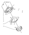
- Figure 1 is an exploded oblique view of a dial-type timer in which this invention has been implemented.
- Dial-type timer 1 in which this invention has been implemented, consists of timer body 2; cover 3, which can be mounted on the face of the said timer body 2; and setting ring 5, which is mounted on dial 4 on timer body 2 when the aforesaid cover 3 is in place.
- Timer body 2 has a dial 4 on its face, as described above. The outer periphery of this dial 4 is formed into grooves 4a, as can be seen in the frontal view in Figure 2 (A). Dial 4 has an indicator 6 and a scale along its circumference for setting the time. It also has a number of windows 7 to display the numerals for the scale, and a window 8 to display the time unit. Along the circumference of dial 4 are POWER and OUT displays 9 and 10, operating function switch 11 and operating function display window 12.
- Figure 2 (B) is a partial side view of the face of timer body 2.
- the structure described above is basically the same as that of the existing timer described in the example.
- the timer of this invention does not have a locking pawl on the upper portion of the face of the timer body 2 to engage in the slot on setting ring 5.
- the locking pawl does not get in the way when dial 4 is operated, so the timer is easier to operate than the existing timer described.
- Cover 3 is mounted on the face of timer body 2 when setting ring 5 is to be used. It has a round opening 13 for dial 4, and openings 14 and 15 for displays 9 and 10 on timer body 2.
- Cover 3 has a single locking pawl 3a molded on its face in a location corresponding to the upper portion of the face of timer body 2 when the cover is mounted on the timer body, as shown in the front view in Figure 3 (A) and the cross section of a side view in Figure 3 (B). This locking pawl engages in the slot on the outer periphery of setting ring 5.
- Setting ring 5 engages in grooves 4a on the outer periphery of dial 4, which projects forward through opening 13 of cover 3 when the cover is mounted on the face of timer body 2.
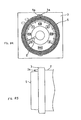
- On the outer periphery of setting ring 5 is slot 5a, into which locking pawl 3a on cover 3 engages, as shown in the front view, cross sectional side view and rear view pictured in Figures 4 (A), (B) and (C).
- pawls 5b are provided, which engage in grooves 4a on the outer periphery of dial 4.
- dial 4 and setting ring 5 are made to rotate as a single entity.
- dial 4 is to reset a repeated operating time, as discussed earlier, it is returned to the position in which locking pawl 3a on cover 3 engages in slot 5a on setting ring 5. This causes the timer to be reset to the aforementioned designated position.
- cover 3 and setting ring 5 of this invention are available in a variety of colors, so they can be chosen to match the color of the panel on which timer body 2 is mounted. This ensures an esthetically pleasing result.
- a cover with a locking pawl on it is mounted on the timer when the setting ring is to be used. This allows the timer to function in the same way as previous timers of this type.
- the cover is removed from the timer so that the locking pawl does not interfere with the operation of the dial. The result is a timer with improved ease of operation.
- This invention relates to a dial-type timer. More specifically, it relates to a dial-type timer which is ideally suited for applications such as process control which require that values once set can be changed only within a limited range.
- dial-type timers when dial-type timers are used in process control, they are set to values which should be changed only within a fixed range.
- the objective of this invention is to make it possible to fix an upper and lower limit for values to be set, and to prevent values which exceed these limits from being set.
- this invention is constructed as follows.
- the dial-type timer described in Paragraph 1 of this application consists of the timer itself, which has a dial on its front to set the operating time; two setting rings mounted on the perimeter of the aforesaid dial in such a way that they rotate as a single piece with that dial; a molded tooth formed on the perimeter of each of the aforesaid setting rings; and a stop on the body of the timer which comes in contact with the aforesaid teeth on the setting rings mounted on the dial so as to limit the range of rotation of that dial.
- the dial-type timer described in Paragraph 2 of this application consists of the timer itself, which has a dial on its front to set the operating time; a cover which can be mounted on the front of the aforesaid timer body, with an opening for the aforesaid dial; two setting rings, which are mounted on the perimeter of the aforesaid dial in such a way that they rotate as a single piece with that dial, which protrudes from the front or the timer through the aforesaid opening in the cover when that cover is mounted on the front of the timer; a molded tooth formed on the perimeter of each of the aforesaid setting rings; and a stop on the aforesaid cover which comes in contact with the aforesaid teeth on the setting rings mounted on the dial so as to limit the range of rotation of that dial.
- the timer of the invention described in Paragraphs 1 and 2 of this application has two setting rings with a tooth on each which can be set in a position to indicate the upper and lower limit of the range of rotation of a dial.
- These setting rings are mounted on the perimeter of the said dial in such a way that the teeth come in contact with a stop on the timer body or its cover. In this way the rotation of the dial is constrained not to go beyond the said positions for upper and lower limits.
- This invention makes it possible to restrict the setting of an operating time to a fixed range defined by the aforesaid upper and lower limits.
- the timer of the invention described in Paragraph 2 of this application has a cover mounted on its face with an opening for the dial.
- This cover encloses and protects the various setting switches and prevents them from being operated inadvertantly. It also allows the color and appearance of the timer to be selected to match the design of the panel on which the timer is mounted. In other words, the addition of a cover allows the design of a dial-type timer to be changed.
- Figure 1 is an oblique exploded view of a dial-type timer in which this invention has been implemented.
- the dial-type timer 1 of this embodiment consists of timer body 2; dial 4, which is used to set the operating time for timer body 2; and setting rings 25 and 35, which are mounted on the perimeter of dial 4. These setting rings limit the range in which dial 4 can be set.
- Stop 36 protrudes from the upper portion of the face of dial 4 on timer body 2. This stop limits the range of rotation of dial 4 when it comes in contact with teeth 25a and 35a on setting rings 25 and 35, as described above.
- the perimeter of dial 4 on timer body 2 is formed into gear teeth 4a.
- Dial 4 has an indicator 6 and a scale along its circumference for setting the time. It also has a number of windows 7 to display the numerals for the scale, and a window 8 to display the time unit. Gear teeth 4a on the perimeter of dial 4 are used to determine the position in which setting rings 25 and 35 are to be mounted, as discussed below.
- Figure 2 (B) is a partial side view of the face of timer body 2.
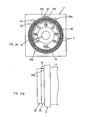
- FIGs 3 (A) and (B) Front and rear views of setting ring 25 are shown in Figures 3 (A) and (B).
- This setting ring is mounted in such a way as to engage in gear teeth 4a on the perimeter of dial 4 on timer body 2. Tooth 25a, which protrudes from the perimeter of the setting ring, comes in contact with stop 36 on timer body 2. Its surface 25c makes contact with surface 36a of stop 36 on the timer body, which is shown in Figure 2 (A).
- teeth 25b In four locations on the inner periphery of setting ring 25 are teeth 25b, which engage in gear teeth 4a on the perimeter of dial 4.
- FIG. 4 A front view of the second setting ring, setting ring 35, is shown in Figure 4.
- This setting ring is also mounted so as to engage in gear teeth 4a on the perimeter of dial 4 on timer body 2. Tooth 35a, which protrudes from the perimeter of the setting ring, comes in contact with stop 36 on timer body 2. Its surface 35c makes contact with surface 36b of stop 36 on the timer body, which is shown in Figure 2 (A).
- teeth 35b In four locations on the inner periphery of setting ring 35 are teeth 35b, which engage in gear teeth 4a on the perimeter of dial 4.
- dial 4 and setting rings 25 and 35 rotate as a single entity, and the setting on dial 4 can be changed only within the range between tooth 25a on setting ring 25 and tooth 35a on setting ring 35. The operator is prevented from setting any value outside of that range.
- a lock generally found in existing timers can be used for stop 36, which protrudes from the surface of the face of timer body 2. This lock protrudes from the upper portion of the face of the timer. It is used to determine the reset position of the setting ring so that it can be reset easily when a standard operating time is being set repeatedly. This lock can be used for both purposes in the new timer.
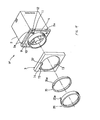
- Figure 6 is an exploded oblique view of another dial-type timer in which this invention has been implemented. Components which correspond to those of the preceding embodiment have been given the same numbering.
- the dial-type timer 1 0 of this embodiment consists of timer body 2 0 ; cover 3, which can be mounted on the face of the aforesaid timer body 2 0 ; and setting rings 25 and 35, which are mounted on the perimeter of dial 4 on timer body 2 o when the aforesaid cover 3 is mounted on timer body 2 0 .
- this timer does not have a stop 36 protruding from the upper portion of dial 4 on timer body 2 0 .
- Cover 3 is already mounted on the face of timer body 2o when setting rings 25 and 35 are used.
- the cover has a round opening 13 for dial 4, and two small openings 14 and 15 for displays 9 and 10 on timer body 2 0 .
- Openings 13 through 15 are the only windows in cover 3.
- operating function switch 11 and the other setting switches are completely enclosed. With the cover in place, there is no possibility that anyone will operate these switches mistakenly.
- Stop 37 protrudes from the surface of cover 3 in a location corresponding to the upper face of the aforesaid timer body 2 0 , as shown in Figure 7 (A), a frontal view, and 7 (B), a cross section of the side. Stop 37 limits the range of rotation of dial 4 when it is contacted by teeth 25a and 35a on setting rings 25 and 35.
- Surface 25c of tooth 25a on setting ring 25 comes in contact with surface 37a of stop 37.
- Surface 35c of tooth 35a on setting ring 35 comes in contact with surface 37b of stop 37.
- dial 4 projects out the front of opening 13 in that cover, and setting rings 25 and 35, which engage with the outer edge 4a of dial 4, are disposed exactly as in the previous example.
- dial-type timer 1 0 which is constructed as described above, the range of settings is controlled by the dial through the use of setting rings 25 and 35.
- cover 3 is mounted on the face of timer body 2 0 .
- Dial 4 is set in the position corresponding to the lower limit of the allowable values, and surface 35c of tooth 35a on setting ring 35 comes in contact with surface 37b of stop 37 on cover 3.
- Setting ring 35 engages with the perimeter of dial 4.
- Dial 4 is then set in the position corresponding to the upper limit of the allowable values, causing surface 25c of tooth 25a on setting ring 25 to come in contact with surface 37a of stop 37 on timer body 2 0 .
- Setting ring 25 then engages with the perimeter of dial 4. This process is illustrated in the frontal view shown in Figure 8 (A) and the partial side view in Figure 8 (B).
- dial 4 and setting rings 25 and 35 rotate as a single entity, and the setting on dial 4 can be changed only within the range between tooth 25a on setting ring 25 and tooth 35a on setting ring 35.
- the operator is prevented from setting any value outside of that range, just as in the previous example.
- cover 3 and setting rings 25 and 35 are available in a variety of colors, so they can be chosen to match the color of the panel on which timer body 2 o is mounted. This ensures an esthetically pleasing result.
- the invention described above has two setting rings, each of which has a single tooth, which set the upper and lower limits of the rotation of a dial.
- These setting rings are mounted in such a way that their teeth come in contact with a stop which protrudes either from the timer itself or from its cover. In this way the rotation of the dial is stopped at the locations corresponding to the upper and lower limits.
- the values of the settings can be changed only within the range defined by the said upper and lower limits. The operator is free to alter the settings without worry.
- the invention described in the paragraph 2 of this application has a cover mounted on the face of the timer. This cover encloses and protects the various setting switches which might cause problems if operated by mistake.
- This invention relates to a timing device in which an output relay is caused to operate by output from a time-limit circuit to measure time which is driven by a DC power supply.
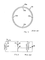
- FIG. 2 The circuit design shown in Figure 2 is well known as a timing device of the type which this invention concerns.
- 1 is the time-limit circuit, which comprises an IC; 2 is the output relay; time-limit circuit 1 and output relay 2 are connected in parallel to DC power supply 3 through switch 4.
- 5 is the output switching element. Its base is connected to the output terminal of the aforesaid time-limit circuit 1. This element is switched on and off by the output from time-limit circuit 1.
- the aforesaid output relay 2 is connected in series with the collector-emitter pathway of output switching element 5.
- 6 in the diagram is a diode used to prevent reverse flow of current.
- current l o is supplied by DC power supply 3.
- This current 1 0 must be equal to 1 1 + 1 2 , that is, to the sum of the current supplied by time-limit circuit 1 and that supplied by output relay 2. It is thus necessary to use a power supply with a current large enough to supply total current 1 0 . Further, the current 1 0 supplied by DC power supply 3 is liable to fluctuate significantly when output relay 2 switches on or off.
- a power supply must be used which has sufficient capacity so that the power supply voltage Vo does not fluctuate when output relay 2 goes on or off. If the power supply does not have sufficient capacity, it will prove difficult to supply stable power to time-limit circuit 1, and the circuit will malfunction.
- This invention was devised in order to solve the problems discussed above. Its objective was to provide a timing device which could use a small-capacity power supply and yet could assure that the supply of power to the time-limit circuit was stable.
- the timing device of this invention is constructed as follows. It has a time-limit circuit to measure the time; an output switching element which goes on or off according to the output from the time-limit circuit; an output relay which operates when the output switching element goes on or off; and a dummy resistor which has virtually the same impedance as the output relay.
- the output relay and the time-limit circuit are connected in series; the said output relay and the dummy resistor are each connected to their own switching elements, which go on and off in complementary fashion at corresponding times. These switching elements are operated by the on or off state of the aforesaid output switching element.
- the output relay and the time-limit circuit are connected in series, and the current flowing into the output relay flows unchanged into the time-limit circuit.
- This arrangement makes it possible to lower the current supplied by the power supply.
- timing current flows along the route consisting of the switching element in parallel with the dummy resistor, and the time-limit circuit.
- the time is up, current flows along the route consisting of the output relay, the switching element in parallel with the dummy resistor, and the time-limit circuit.
- the current then, is not affected by the output relay being switched on or off.
- a steady current flows, and there is minimum fluctuation of current in the circuit as a whole.
- stable power can be supplied to the time-limit circuit.
- Figure 1 shows the configuration of the circuit in a timing device in which this invention has been implemented.
- Numbers 1 through 6 in this diagram refer to components identical to those in the example of an existing timer. They have been given the same numbers, and their explanation has been omitted.
- 7 is the dummy resistor with virtually the same impedance as output relay 2.
- Dummy resistor 7 and output relay 2 are connected to time-limit circuit 1 in series.
- 8 and 9 are the switching elements connected in parallel to the aforesaid output relay 2 and dummy resistor 7, respectively. These switching elements are operated by the switching on or off of output switching element 5 in such a way that when one goes on, the other goes off.
- timing is begun when switch 4 is thrown.
- current I which supplied by DC power supply 3 flows into switching element 8 and dummy resistor 7, as shown by the dotted arrow, and the specified power is supplied to time-limit circuit 1.
- the aforesaid time-limit circuit determines that the time is up, and its output causes switching element 5 to go on.
- element 5 switches on, the aforesaid switching element 8 goes off, and switching element 9 goes on.
- Current I from DC power supply 3 flows into output relay 2 and switching element 9, as shown by the solid arrow, and the specified power is supplied to time-limit circuit 1.
- the impedance Ry of the aforesaid output relay 2 and R 1 of dummy resistor 7 are virtually identical, so the current does not vary either during timing or when timing has been completed. A virtually constant current is made to flow, and stable power can be supplied to time-limit circuit 1.
- this invention entails connecting the output relay and the time-limit circuit in series so that the current which goes into the output relay flows unchanged into the time-limit circuit. This being the case, less current is required of the power supply, and a lower-capacity power supply can be used. Furthermore, there is virtually no fluctuation of current either during timing or when timing has been completed, so a constant current is made to flow regardless of whether the output relay is on or off. Current fluctuation is minimized throughout the circuit, stable power can be supplied to the time-limit circuit, and malfunctions can effectively be prevented.
Landscapes
- Physics & Mathematics (AREA)
- General Physics & Mathematics (AREA)
- Measurement Of Predetermined Time Intervals (AREA)
- Electromechanical Clocks (AREA)
- Rotary Switch, Piano Key Switch, And Lever Switch (AREA)
- Electric Clocks (AREA)
- Electronic Switches (AREA)
Priority Applications (1)
| Application Number | Priority Date | Filing Date | Title |
|---|---|---|---|
| EP95120410A EP0715234B1 (de) | 1991-05-10 | 1992-05-11 | Zeitmesser mit Zifferblatt |
Applications Claiming Priority (6)
| Application Number | Priority Date | Filing Date | Title |
|---|---|---|---|
| JP10572591A JP2674354B2 (ja) | 1991-05-10 | 1991-05-10 | ダイアル式タイマ |
| JP105725/91 | 1991-05-10 | ||
| JP62626/91U | 1991-07-12 | ||
| JP6262691U JPH056628U (ja) | 1991-07-12 | 1991-07-12 | タイマ装置 |
| JP179573/91 | 1991-07-19 | ||
| JP3179573A JP2767656B2 (ja) | 1991-07-19 | 1991-07-19 | ダイアル式タイマ |
Related Child Applications (2)
| Application Number | Title | Priority Date | Filing Date |
|---|---|---|---|
| EP95120410A Division EP0715234B1 (de) | 1991-05-10 | 1992-05-11 | Zeitmesser mit Zifferblatt |
| EP95120410.6 Division-Into | 1995-12-22 |
Publications (3)
| Publication Number | Publication Date |
|---|---|
| EP0512574A2 true EP0512574A2 (de) | 1992-11-11 |
| EP0512574A3 EP0512574A3 (en) | 1993-08-11 |
| EP0512574B1 EP0512574B1 (de) | 1997-08-20 |
Family
ID=27297900
Family Applications (2)
| Application Number | Title | Priority Date | Filing Date |
|---|---|---|---|
| EP92107901A Expired - Lifetime EP0512574B1 (de) | 1991-05-10 | 1992-05-11 | Zeitmesser mit Zifferblatt |
| EP95120410A Expired - Lifetime EP0715234B1 (de) | 1991-05-10 | 1992-05-11 | Zeitmesser mit Zifferblatt |
Family Applications After (1)
| Application Number | Title | Priority Date | Filing Date |
|---|---|---|---|
| EP95120410A Expired - Lifetime EP0715234B1 (de) | 1991-05-10 | 1992-05-11 | Zeitmesser mit Zifferblatt |
Country Status (4)
| Country | Link |
|---|---|
| US (1) | US5400302A (de) |
| EP (2) | EP0512574B1 (de) |
| AT (2) | ATE189536T1 (de) |
| DE (2) | DE69230649T2 (de) |
Cited By (1)
| Publication number | Priority date | Publication date | Assignee | Title |
|---|---|---|---|---|
| CN111465905A (zh) * | 2017-12-21 | 2020-07-28 | Eta瑞士钟表制造股份有限公司 | 包括表盘附接装置的钟表 |
Families Citing this family (9)
| Publication number | Priority date | Publication date | Assignee | Title |
|---|---|---|---|---|
| US5715214A (en) * | 1996-07-03 | 1998-02-03 | Intermatic Incorporated | Electrical timer with setting window |
| US5831230A (en) * | 1996-12-20 | 1998-11-03 | Emerson Electric Co. | Appliance timer having a cam which is operated at multiple speeds |
| US5814776A (en) * | 1997-02-27 | 1998-09-29 | Emerson Electric Co. | Appliance timer having coupling mechanism that prevents camstack from rotating in inappropriate direction |
| US6062985A (en) * | 1998-05-06 | 2000-05-16 | Rege; Kathleen | Golf flag stick play pacer |
| US6080943A (en) * | 1999-08-02 | 2000-06-27 | France/Scott Fetzer Company | Timer |
| US6797897B2 (en) * | 1999-08-02 | 2004-09-28 | France/Scott Fetzer Company | Timer |
| US6441326B1 (en) | 1999-08-02 | 2002-08-27 | France/Scott Fetzer Company | Timer |
| US6583371B1 (en) | 2001-11-02 | 2003-06-24 | France/Scott Fetzer Company | Timer |
| US7463556B2 (en) * | 2003-09-17 | 2008-12-09 | American Innovative, Llc | Alarm device |
Family Cites Families (7)
| Publication number | Priority date | Publication date | Assignee | Title |
|---|---|---|---|---|
| US3693119A (en) * | 1970-09-25 | 1972-09-19 | Katuhiko Nakama | Electrical timing device |
| DE2164330A1 (de) * | 1971-12-23 | 1973-06-28 | Automatic Timing & Controls | Verzoegerungsrelais |
| US3823547A (en) * | 1973-02-07 | 1974-07-16 | Gulf & Western Industries | Reset timer |
| DE7432974U (de) * | 1974-10-01 | 1976-04-08 | Philips Patentverwaltung Gmbh, 2000 Hamburg | Vormerkvorrichtung an uhren |
| JPS6175286A (ja) * | 1984-09-19 | 1986-04-17 | Matsushita Electric Works Ltd | 時計 |
| DE8436475U1 (de) * | 1984-12-13 | 1985-03-14 | Braun Ag, 6000 Frankfurt | Stellvorrichtung für einen Kurzzeitmesser |
| JPH0327384U (de) * | 1989-07-27 | 1991-03-19 |
-
1992
- 1992-05-11 AT AT95120410T patent/ATE189536T1/de not_active IP Right Cessation
- 1992-05-11 EP EP92107901A patent/EP0512574B1/de not_active Expired - Lifetime
- 1992-05-11 DE DE69230649T patent/DE69230649T2/de not_active Expired - Lifetime
- 1992-05-11 EP EP95120410A patent/EP0715234B1/de not_active Expired - Lifetime
- 1992-05-11 AT AT92107901T patent/ATE157179T1/de active
- 1992-05-11 DE DE69221662T patent/DE69221662T2/de not_active Expired - Lifetime
-
1994
- 1994-06-21 US US08/263,485 patent/US5400302A/en not_active Expired - Lifetime
Cited By (2)
| Publication number | Priority date | Publication date | Assignee | Title |
|---|---|---|---|---|
| CN111465905A (zh) * | 2017-12-21 | 2020-07-28 | Eta瑞士钟表制造股份有限公司 | 包括表盘附接装置的钟表 |
| CN111465905B (zh) * | 2017-12-21 | 2022-09-02 | Eta瑞士钟表制造股份有限公司 | 包括表盘附接装置的钟表 |
Also Published As
| Publication number | Publication date |
|---|---|
| DE69221662T2 (de) | 1998-04-02 |
| DE69221662D1 (de) | 1997-09-25 |
| EP0512574B1 (de) | 1997-08-20 |
| US5400302A (en) | 1995-03-21 |
| EP0715234B1 (de) | 2000-02-02 |
| DE69230649T2 (de) | 2000-09-21 |
| DE69230649D1 (de) | 2000-03-09 |
| EP0715234A1 (de) | 1996-06-05 |
| EP0512574A3 (en) | 1993-08-11 |
| ATE157179T1 (de) | 1997-09-15 |
| ATE189536T1 (de) | 2000-02-15 |
Similar Documents
| Publication | Publication Date | Title |
|---|---|---|
| EP0715234A1 (de) | Zeitmesser mit Zifferblatt | |
| US6203190B1 (en) | Crown switching mechanism | |
| US5016230A (en) | Timing | |
| US5231310A (en) | Electrical and electronic appliance lock | |
| KR960024806A (ko) | 다중클럭 선택권을 가지는 마이크로프로세서에서의 자기구성 속도경로 | |
| GB1602051A (en) | Motor speed adjusting apparatus | |
| US5008870A (en) | FIFO clock | |
| US4421418A (en) | Clock adjustment switch system | |
| EP0662557A3 (de) | Kombinationsschloss mit vier Einstellknöpfen. | |
| US3142148A (en) | Indicator | |
| US4410774A (en) | Single knob variable range timer | |
| KR0180747B1 (ko) | 다이얼식 타이머 | |
| JPS5929835B2 (ja) | 電子腕時計 | |
| US4974217A (en) | Scale indicator used with electronic setting apparatus for setting numerical values of physical quantities or the like | |
| KR860000790B1 (ko) | 전자시계 | |
| US4102122A (en) | Electronic watch | |
| US6570822B2 (en) | Time period setting structure of timer | |
| US6604851B1 (en) | Method for setting a multimode electronic device | |
| US2918969A (en) | Program clock | |
| JPS60143537A (ja) | タイマ− | |
| KR930008948B1 (ko) | 전자레인지의 요리시간 설정방법 | |
| JPH0424586Y2 (de) | ||
| JPS625675Y2 (de) | ||
| JPH0142077Y2 (de) | ||
| JPS6015893Y2 (ja) | 電子錠装置 |
Legal Events
| Date | Code | Title | Description |
|---|---|---|---|
| PUAI | Public reference made under article 153(3) epc to a published international application that has entered the european phase |
Free format text: ORIGINAL CODE: 0009012 |
|
| 17P | Request for examination filed |
Effective date: 19920605 |
|
| AK | Designated contracting states |
Kind code of ref document: A2 Designated state(s): AT BE CH DE DK ES FR GB GR IT LI MC NL PT SE |
|
| PUAL | Search report despatched |
Free format text: ORIGINAL CODE: 0009013 |
|
| AK | Designated contracting states |
Kind code of ref document: A3 Designated state(s): AT BE CH DE DK ES FR GB GR IT LI MC NL PT SE |
|
| 17Q | First examination report despatched |
Effective date: 19950207 |
|
| GRAG | Despatch of communication of intention to grant |
Free format text: ORIGINAL CODE: EPIDOS AGRA |
|
| GRAH | Despatch of communication of intention to grant a patent |
Free format text: ORIGINAL CODE: EPIDOS IGRA |
|
| GRAH | Despatch of communication of intention to grant a patent |
Free format text: ORIGINAL CODE: EPIDOS IGRA |
|
| GRAA | (expected) grant |
Free format text: ORIGINAL CODE: 0009210 |
|
| AK | Designated contracting states |
Kind code of ref document: B1 Designated state(s): AT BE CH DE DK ES FR GB GR IT LI MC NL PT SE |
|
| DX | Miscellaneous (deleted) | ||
| PG25 | Lapsed in a contracting state [announced via postgrant information from national office to epo] |
Ref country code: NL Free format text: LAPSE BECAUSE OF FAILURE TO SUBMIT A TRANSLATION OF THE DESCRIPTION OR TO PAY THE FEE WITHIN THE PRESCRIBED TIME-LIMIT Effective date: 19970820 Ref country code: BE Effective date: 19970820 Ref country code: LI Free format text: LAPSE BECAUSE OF FAILURE TO SUBMIT A TRANSLATION OF THE DESCRIPTION OR TO PAY THE FEE WITHIN THE PRESCRIBED TIME-LIMIT Effective date: 19970820 Ref country code: ES Free format text: THE PATENT HAS BEEN ANNULLED BY A DECISION OF A NATIONAL AUTHORITY Effective date: 19970820 Ref country code: AT Effective date: 19970820 Ref country code: GR Free format text: LAPSE BECAUSE OF FAILURE TO SUBMIT A TRANSLATION OF THE DESCRIPTION OR TO PAY THE FEE WITHIN THE PRESCRIBED TIME-LIMIT Effective date: 19970820 Ref country code: CH Free format text: LAPSE BECAUSE OF FAILURE TO SUBMIT A TRANSLATION OF THE DESCRIPTION OR TO PAY THE FEE WITHIN THE PRESCRIBED TIME-LIMIT Effective date: 19970820 Ref country code: DK Free format text: LAPSE BECAUSE OF NON-PAYMENT OF DUE FEES Effective date: 19970820 |
|
| REF | Corresponds to: |
Ref document number: 157179 Country of ref document: AT Date of ref document: 19970915 Kind code of ref document: T |
|
| REG | Reference to a national code |
Ref country code: CH Ref legal event code: EP |
|
| ITF | It: translation for a ep patent filed | ||
| REF | Corresponds to: |
Ref document number: 69221662 Country of ref document: DE Date of ref document: 19970925 |
|
| ET | Fr: translation filed | ||
| PG25 | Lapsed in a contracting state [announced via postgrant information from national office to epo] |
Ref country code: SE Effective date: 19971120 Ref country code: PT Effective date: 19971120 |
|
| NLV1 | Nl: lapsed or annulled due to failure to fulfill the requirements of art. 29p and 29m of the patents act | ||
| REG | Reference to a national code |
Ref country code: CH Ref legal event code: PL |
|
| PG25 | Lapsed in a contracting state [announced via postgrant information from national office to epo] |
Ref country code: GB Free format text: LAPSE BECAUSE OF NON-PAYMENT OF DUE FEES Effective date: 19980511 |
|
| PLBE | No opposition filed within time limit |
Free format text: ORIGINAL CODE: 0009261 |
|
| STAA | Information on the status of an ep patent application or granted ep patent |
Free format text: STATUS: NO OPPOSITION FILED WITHIN TIME LIMIT |
|
| 26N | No opposition filed | ||
| PG25 | Lapsed in a contracting state [announced via postgrant information from national office to epo] |
Ref country code: MC Free format text: LAPSE BECAUSE OF NON-PAYMENT OF DUE FEES Effective date: 19981130 |
|
| GBPC | Gb: european patent ceased through non-payment of renewal fee |
Effective date: 19980511 |
|
| PG25 | Lapsed in a contracting state [announced via postgrant information from national office to epo] |
Ref country code: IT Free format text: LAPSE BECAUSE OF NON-PAYMENT OF DUE FEES;WARNING: LAPSES OF ITALIAN PATENTS WITH EFFECTIVE DATE BEFORE 2007 MAY HAVE OCCURRED AT ANY TIME BEFORE 2007. THE CORRECT EFFECTIVE DATE MAY BE DIFFERENT FROM THE ONE RECORDED. Effective date: 20050511 |
|
| PGRI | Patent reinstated in contracting state [announced from national office to epo] |
Ref country code: IT Effective date: 20091201 |
|
| PGFP | Annual fee paid to national office [announced via postgrant information from national office to epo] |
Ref country code: FR Payment date: 20110523 Year of fee payment: 20 |
|
| PGFP | Annual fee paid to national office [announced via postgrant information from national office to epo] |
Ref country code: DE Payment date: 20110531 Year of fee payment: 20 Ref country code: IT Payment date: 20110524 Year of fee payment: 20 |
|
| REG | Reference to a national code |
Ref country code: DE Ref legal event code: R071 Ref document number: 69221662 Country of ref document: DE |
|
| REG | Reference to a national code |
Ref country code: DE Ref legal event code: R071 Ref document number: 69221662 Country of ref document: DE |
|
| PG25 | Lapsed in a contracting state [announced via postgrant information from national office to epo] |
Ref country code: DE Free format text: LAPSE BECAUSE OF EXPIRATION OF PROTECTION Effective date: 20120512 |
|
| REG | Reference to a national code |
Ref country code: DE Ref legal event code: R082 Ref document number: 69221662 Country of ref document: DE Representative=s name: KILIAN KILIAN & PARTNER, DE Ref country code: DE Ref legal event code: R082 Ref document number: 69221662 Country of ref document: DE Representative=s name: KILIAN KILIAN & PARTNER MBB PATENTANWAELTE, DE |