EP0513020B1 - Injecteur de carburant avec raccordement au circuit de retour d'huile - Google Patents
Injecteur de carburant avec raccordement au circuit de retour d'huile Download PDFInfo
- Publication number
- EP0513020B1 EP0513020B1 EP91901696A EP91901696A EP0513020B1 EP 0513020 B1 EP0513020 B1 EP 0513020B1 EP 91901696 A EP91901696 A EP 91901696A EP 91901696 A EP91901696 A EP 91901696A EP 0513020 B1 EP0513020 B1 EP 0513020B1
- Authority
- EP
- European Patent Office
- Prior art keywords
- bolt
- injection nozzle
- fuel
- overflow
- head
- Prior art date
- Legal status (The legal status is an assumption and is not a legal conclusion. Google has not performed a legal analysis and makes no representation as to the accuracy of the status listed.)
- Expired - Lifetime
Links
- 238000002347 injection Methods 0.000 title claims abstract description 10
- 239000007924 injection Substances 0.000 title claims abstract description 10
- 239000000446 fuel Substances 0.000 claims description 9
- 238000004519 manufacturing process Methods 0.000 description 3
- 210000002445 nipple Anatomy 0.000 description 3
- 238000005496 tempering Methods 0.000 description 2
- 241000538562 Banjos Species 0.000 description 1
- 229910000831 Steel Inorganic materials 0.000 description 1
- 230000002411 adverse Effects 0.000 description 1
- 238000005553 drilling Methods 0.000 description 1
- 238000004049 embossing Methods 0.000 description 1
- 238000009434 installation Methods 0.000 description 1
- 238000007789 sealing Methods 0.000 description 1
- 239000010959 steel Substances 0.000 description 1
- 238000005482 strain hardening Methods 0.000 description 1
Images
Classifications
-
- F—MECHANICAL ENGINEERING; LIGHTING; HEATING; WEAPONS; BLASTING
- F02—COMBUSTION ENGINES; HOT-GAS OR COMBUSTION-PRODUCT ENGINE PLANTS
- F02M—SUPPLYING COMBUSTION ENGINES IN GENERAL WITH COMBUSTIBLE MIXTURES OR CONSTITUENTS THEREOF
- F02M55/00—Fuel-injection apparatus characterised by their fuel conduits or their venting means; Arrangements of conduits between fuel tank and pump F02M37/00
- F02M55/004—Joints; Sealings
Definitions
- the invention relates to a fuel injector with a leakage oil connection according to the preamble of claim 1.
- a cap screw with an axial blind hole in the threaded shaft and a transverse hole near the head is mainly used, with which a collecting ring with a connecting nipple is pressed tightly against the nozzle holder.
- a banjo bolt is made of steel by several processing operations such as turning, drilling, deburring and tempering.
- the passage for the leak oil is designed in the form of longitudinal grooves in the circumference of the threaded shaft of the cap screw.
- the longitudinal grooves have a U-shaped cross-section and run helically in the thread of the shaft.
- a disadvantage of the known fuel injection nozzle is that burrs or ridges occur in the manufacture of the grooves in the threaded shaft, which adversely affect the dimensional accuracy of the thread.
- the object of the invention is to provide for the leakage oil connection to a fuel injector, a screw for connecting the collecting ring, the manufacture of which is simple and cheap, and in which the dimensional accuracy of the thread is very high for safe and simple installation.
- the leakage oil connection of the fuel injection nozzle according to the characterizing feature of claim 1 has the Advantage that the screw that allows the leakage oil to the collecting ring can be produced by cold working. This manufacturing process, which is essentially reduced to cold forming, also eliminates the need for hardening and tempering.
- the thread which can be produced in a simple manner with high precision and with interruptions in the area of the flats, can be formed on the shank of the cap screw by first cold-knocking the shank with the flats and then embossing the thread, so that the deformation areas on the thread part ends are displaced into the flats will.
- the division of the die preferably lies in the center line of the flats, so that burrs can be avoided at all.
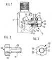
- FIG. 1 shows a part of a nozzle holder with a leakage oil connection of a fuel injection nozzle in a longitudinal view, partly in section
- FIG. 2 shows an embodiment of a cap screw of the leakage oil connection in a longitudinal view
- FIG. 3 shows the cap screw according to FIG. 2 in a plan view.
- a nozzle holder 1 of a fuel injection nozzle has a channel 2 for returning the leak oil, which opens into a threaded bore 3.
- a leakage oil connection 5 is connected to this threaded bore 3 and has a cap screw 10 with a threaded shaft 11 and with a head 12 and a collecting ring 14.
- the collecting ring 14, which has an inner annular groove 15 and a connecting nipple 16, is threaded onto the threaded shaft 11 of the screw 10 and pressed wildly by the head 12 of the screw 10 with the interposition of two sealing rings 17 against the nozzle holder 1.
- the screw 10 has several, preferably four, longitudinal grooves 20 in the circumference of its threaded shaft 11, in the area of which the thread is interrupted.
- the longitudinal grooves 20 run from the free end of the shaft 11 to close to the head 12 of the screw 10.
- two grooves 20 are formed in the form of flats 22 on the shaft 11 of the screw 10.
- the thread and the flats 22 are formed by cold hammering, the die division running in the center line of the flats 22.
Landscapes
- Engineering & Computer Science (AREA)
- Chemical & Material Sciences (AREA)
- Combustion & Propulsion (AREA)
- Mechanical Engineering (AREA)
- General Engineering & Computer Science (AREA)
- Fuel-Injection Apparatus (AREA)
Abstract
Claims (2)
- Injecteur de carburant avec raccordement au circuit de retour d'huile, comportant, montée dans un alésage fileté du support d'injecteur (1), une vis à tête (10) équipée d'un canal de passage ayant la forme de rainures (22) pratiquées à la périphérie de la tige filetée (11) ainsi qu'une bague collectrice (14) serrée entre la tête (12) de la vis (10) et le support (1) d'injecteur, caractérisé en ce que les rainures sont constituées par des parties aplaties (22) de la tige (11) de la vis (10).
- Injecteur de carburant selon la revendication 1, caractérisé en ce que les parties aplaties (22) sont diamétralement opposées sur la tige (11) de la vis (10).
Applications Claiming Priority (3)
| Application Number | Priority Date | Filing Date | Title |
|---|---|---|---|
| DE9001194U DE9001194U1 (de) | 1990-02-03 | 1990-02-03 | Kraftstoffeinspritzdüse mit Leckölanschluß |
| DE9001194U | 1990-02-03 | ||
| PCT/DE1991/000030 WO1991011606A1 (fr) | 1990-02-03 | 1991-01-17 | Injecteur de carburant avec raccordement au circuit de retour d'huile |
Publications (2)
| Publication Number | Publication Date |
|---|---|
| EP0513020A1 EP0513020A1 (fr) | 1992-11-19 |
| EP0513020B1 true EP0513020B1 (fr) | 1994-09-14 |
Family
ID=6850625
Family Applications (1)
| Application Number | Title | Priority Date | Filing Date |
|---|---|---|---|
| EP91901696A Expired - Lifetime EP0513020B1 (fr) | 1990-02-03 | 1991-01-17 | Injecteur de carburant avec raccordement au circuit de retour d'huile |
Country Status (5)
| Country | Link |
|---|---|
| EP (1) | EP0513020B1 (fr) |
| JP (1) | JP2851425B2 (fr) |
| BR (1) | BR9105979A (fr) |
| DE (2) | DE9001194U1 (fr) |
| WO (1) | WO1991011606A1 (fr) |
Families Citing this family (4)
| Publication number | Priority date | Publication date | Assignee | Title |
|---|---|---|---|---|
| DE10201353B4 (de) * | 2002-01-16 | 2004-04-08 | Daimlerchrysler Ag | Hochdruckanschluss für ein Kraftstoffeinspritzsystem für Brennkraftmaschinen |
| CN108940626A (zh) * | 2018-09-05 | 2018-12-07 | 红塔烟草(集团)有限责任公司 | 一种喷嘴防溢漏装置 |
| CN111830410B (zh) * | 2020-07-24 | 2022-11-29 | 上海外高桥造船有限公司 | 一种柴油发电机组油头试验固定及集油装置 |
| USD1023736S1 (en) | 2022-10-27 | 2024-04-23 | Fleece Performance Engineering, Inc. | Bolt |
Family Cites Families (3)
| Publication number | Priority date | Publication date | Assignee | Title |
|---|---|---|---|---|
| GB1521875A (en) * | 1977-03-08 | 1978-08-16 | Zuev A | Fluid conduit apparatus and a method of making same |
| JPS5752376Y2 (fr) * | 1979-02-26 | 1982-11-13 | ||
| DE8104261U1 (de) * | 1981-02-17 | 1981-08-06 | Robert Bosch Gmbh, 7000 Stuttgart | Fluessigkeitsgekuehlte kraftstoffeinspritzduese |
-
1990
- 1990-02-03 DE DE9001194U patent/DE9001194U1/de not_active Expired - Lifetime
-
1991
- 1991-01-17 BR BR919105979A patent/BR9105979A/pt not_active IP Right Cessation
- 1991-01-17 JP JP3502187A patent/JP2851425B2/ja not_active Expired - Lifetime
- 1991-01-17 EP EP91901696A patent/EP0513020B1/fr not_active Expired - Lifetime
- 1991-01-17 DE DE59102948T patent/DE59102948D1/de not_active Expired - Lifetime
- 1991-01-17 WO PCT/DE1991/000030 patent/WO1991011606A1/fr not_active Ceased
Also Published As
| Publication number | Publication date |
|---|---|
| BR9105979A (pt) | 1992-11-10 |
| EP0513020A1 (fr) | 1992-11-19 |
| DE9001194U1 (de) | 1991-05-29 |
| JP2851425B2 (ja) | 1999-01-27 |
| WO1991011606A1 (fr) | 1991-08-08 |
| JPH05504389A (ja) | 1993-07-08 |
| DE59102948D1 (de) | 1994-10-20 |
Similar Documents
| Publication | Publication Date | Title |
|---|---|---|
| DE19729392C2 (de) | Kraftstoffspeicher mit Abdichtung | |
| DE4307090A1 (de) | Mutter, insbesondere Radmutter | |
| WO1991010062A1 (fr) | Pompe d'injection de carburant a commande electrique pour moteurs a combustion interne, en particulier pompe d'injection combinee avec l'injecteur | |
| DE102015122309A1 (de) | Rohrverbindung | |
| EP1373715A1 (fr) | Soupape d'injection de carburant pour moteurs a combustion interne | |
| EP1407133A1 (fr) | Soupape d'injection de carburant pour moteurs a combustion interne | |
| DE4407306C1 (de) | Druckleitungsanschluß | |
| DE10102233A1 (de) | Kraftstoffhochdrucksystem für Brennkraftmaschinen | |
| DE4307092B4 (de) | Mutter, insbesondere Radmutter | |
| DE3420646C2 (fr) | ||
| DE10353168A1 (de) | Verfahren und Vorrichtung zum hydroerosiven Verrunden von Bohrungsübergängen | |
| WO1991011606A1 (fr) | Injecteur de carburant avec raccordement au circuit de retour d'huile | |
| DE4408245A1 (de) | Einspritzdüse für Brennkraftmaschinen | |
| EP1373713B1 (fr) | Dispositif d'injection de carburant, notamment injecteur, pour moteurs a combustion interne | |
| DE10307873A1 (de) | Sackloch- und Sitzloch-Einspritzdüse für eine Brennkraftmaschine mit einem Übergangskegel zwischen Sackloch und Düsennadelsitz | |
| EP2902614A1 (fr) | Rondelle d'étanchéité pour un injecteur de carburant et injecteur de carburant avec une telle rondelle d'étanchéité | |
| EP1042609B1 (fr) | Soupape d'injection de carburant pour moteurs a combustion interne | |
| WO2001057394A1 (fr) | Soupape d'injection de carburant pour moteurs a combustion interne | |
| EP1771655B1 (fr) | Ecrou de serrage | |
| DE10114216B4 (de) | Streckgrenzengesteuerte Schraubverbindung | |
| DE4307091A1 (de) | Mutter, insbesondere Radmutter | |
| DE69206235T2 (de) | Kraftstoffilter. | |
| EP1446575B1 (fr) | Soupape d'injection de carburant pour moteurs a combustion interne | |
| DE102017125435A1 (de) | Kraftstoffeinspritzsystem, Überwurfmutter für ein Kraftstoffeinspritzsystem sowie Verfahren zum Herstellen einer solchen Überwurfmutter | |
| EP1017938B1 (fr) | Soupape d'injection de carburant pour moteur a combustion interne |
Legal Events
| Date | Code | Title | Description |
|---|---|---|---|
| PUAI | Public reference made under article 153(3) epc to a published international application that has entered the european phase |
Free format text: ORIGINAL CODE: 0009012 |
|
| AK | Designated contracting states |
Kind code of ref document: A1 Designated state(s): DE FR GB IT |
|
| 17P | Request for examination filed |
Effective date: 19920702 |
|
| 17Q | First examination report despatched |
Effective date: 19931005 |
|
| GRAA | (expected) grant |
Free format text: ORIGINAL CODE: 0009210 |
|
| AK | Designated contracting states |
Kind code of ref document: B1 Designated state(s): DE FR GB IT |
|
| ET | Fr: translation filed | ||
| REF | Corresponds to: |
Ref document number: 59102948 Country of ref document: DE Date of ref document: 19941020 |
|
| GBT | Gb: translation of ep patent filed (gb section 77(6)(a)/1977) |
Effective date: 19940923 |
|
| ITF | It: translation for a ep patent filed | ||
| PLBE | No opposition filed within time limit |
Free format text: ORIGINAL CODE: 0009261 |
|
| STAA | Information on the status of an ep patent application or granted ep patent |
Free format text: STATUS: NO OPPOSITION FILED WITHIN TIME LIMIT |
|
| 26N | No opposition filed | ||
| REG | Reference to a national code |
Ref country code: GB Ref legal event code: IF02 |
|
| PG25 | Lapsed in a contracting state [announced via postgrant information from national office to epo] |
Ref country code: IT Free format text: LAPSE BECAUSE OF NON-PAYMENT OF DUE FEES;WARNING: LAPSES OF ITALIAN PATENTS WITH EFFECTIVE DATE BEFORE 2007 MAY HAVE OCCURRED AT ANY TIME BEFORE 2007. THE CORRECT EFFECTIVE DATE MAY BE DIFFERENT FROM THE ONE RECORDED. Effective date: 20050117 |
|
| PGRI | Patent reinstated in contracting state [announced from national office to epo] |
Ref country code: IT Effective date: 20080301 |
|
| PGFP | Annual fee paid to national office [announced via postgrant information from national office to epo] |
Ref country code: IT Payment date: 20100125 Year of fee payment: 20 Ref country code: FR Payment date: 20100209 Year of fee payment: 20 |
|
| PGFP | Annual fee paid to national office [announced via postgrant information from national office to epo] |
Ref country code: GB Payment date: 20100121 Year of fee payment: 20 |
|
| PGFP | Annual fee paid to national office [announced via postgrant information from national office to epo] |
Ref country code: DE Payment date: 20100324 Year of fee payment: 20 |
|
| REG | Reference to a national code |
Ref country code: GB Ref legal event code: PE20 Expiry date: 20110116 |
|
| PG25 | Lapsed in a contracting state [announced via postgrant information from national office to epo] |
Ref country code: GB Free format text: LAPSE BECAUSE OF EXPIRATION OF PROTECTION Effective date: 20110116 |
|
| PG25 | Lapsed in a contracting state [announced via postgrant information from national office to epo] |
Ref country code: DE Free format text: LAPSE BECAUSE OF EXPIRATION OF PROTECTION Effective date: 20110117 |