EP0513794A2 - Boîte pour la sangle d'un volet roulant ou élément de traction similaire - Google Patents
Boîte pour la sangle d'un volet roulant ou élément de traction similaire Download PDFInfo
- Publication number
- EP0513794A2 EP0513794A2 EP92108165A EP92108165A EP0513794A2 EP 0513794 A2 EP0513794 A2 EP 0513794A2 EP 92108165 A EP92108165 A EP 92108165A EP 92108165 A EP92108165 A EP 92108165A EP 0513794 A2 EP0513794 A2 EP 0513794A2
- Authority
- EP
- European Patent Office
- Prior art keywords
- housing
- wall
- control device
- switching control
- belt
- Prior art date
- Legal status (The legal status is an assumption and is not a legal conclusion. Google has not performed a legal analysis and makes no representation as to the accuracy of the status listed.)
- Granted
Links
Images

Classifications
-
- E—FIXED CONSTRUCTIONS
- E06—DOORS, WINDOWS, SHUTTERS, OR ROLLER BLINDS IN GENERAL; LADDERS
- E06B—FIXED OR MOVABLE CLOSURES FOR OPENINGS IN BUILDINGS, VEHICLES, FENCES OR LIKE ENCLOSURES IN GENERAL, e.g. DOORS, WINDOWS, BLINDS, GATES
- E06B9/00—Screening or protective devices for wall or similar openings, with or without operating or securing mechanisms; Closures of similar construction
- E06B9/56—Operating, guiding or securing devices or arrangements for roll-type closures; Spring drums; Tape drums; Counterweighting arrangements therefor
- E06B9/68—Operating devices or mechanisms, e.g. with electric drive
- E06B9/70—Operating devices or mechanisms, e.g. with electric drive comprising an electric motor positioned outside the roller
-
- E—FIXED CONSTRUCTIONS
- E06—DOORS, WINDOWS, SHUTTERS, OR ROLLER BLINDS IN GENERAL; LADDERS
- E06B—FIXED OR MOVABLE CLOSURES FOR OPENINGS IN BUILDINGS, VEHICLES, FENCES OR LIKE ENCLOSURES IN GENERAL, e.g. DOORS, WINDOWS, BLINDS, GATES
- E06B9/00—Screening or protective devices for wall or similar openings, with or without operating or securing mechanisms; Closures of similar construction
- E06B9/24—Screens or other constructions affording protection against light, especially against sunshine; Similar screens for privacy or appearance; Slat blinds
- E06B9/26—Lamellar or like blinds, e.g. venetian blinds
- E06B9/28—Lamellar or like blinds, e.g. venetian blinds with horizontal lamellae, e.g. non-liftable
- E06B9/30—Lamellar or like blinds, e.g. venetian blinds with horizontal lamellae, e.g. non-liftable liftable
- E06B9/32—Operating, guiding, or securing devices therefor
-
- E—FIXED CONSTRUCTIONS
- E06—DOORS, WINDOWS, SHUTTERS, OR ROLLER BLINDS IN GENERAL; LADDERS
- E06B—FIXED OR MOVABLE CLOSURES FOR OPENINGS IN BUILDINGS, VEHICLES, FENCES OR LIKE ENCLOSURES IN GENERAL, e.g. DOORS, WINDOWS, BLINDS, GATES
- E06B9/00—Screening or protective devices for wall or similar openings, with or without operating or securing mechanisms; Closures of similar construction
- E06B9/56—Operating, guiding or securing devices or arrangements for roll-type closures; Spring drums; Tape drums; Counterweighting arrangements therefor
- E06B9/68—Operating devices or mechanisms, e.g. with electric drive
- E06B2009/6809—Control
- E06B2009/6818—Control using sensors
- E06B2009/6836—Control using sensors sensing obstacle
-
- E—FIXED CONSTRUCTIONS
- E06—DOORS, WINDOWS, SHUTTERS, OR ROLLER BLINDS IN GENERAL; LADDERS
- E06B—FIXED OR MOVABLE CLOSURES FOR OPENINGS IN BUILDINGS, VEHICLES, FENCES OR LIKE ENCLOSURES IN GENERAL, e.g. DOORS, WINDOWS, BLINDS, GATES
- E06B9/00—Screening or protective devices for wall or similar openings, with or without operating or securing mechanisms; Closures of similar construction
- E06B9/56—Operating, guiding or securing devices or arrangements for roll-type closures; Spring drums; Tape drums; Counterweighting arrangements therefor
- E06B9/68—Operating devices or mechanisms, e.g. with electric drive
- E06B2009/6809—Control
- E06B2009/6818—Control using sensors
- E06B2009/6845—Control using sensors sensing position
Definitions
- the invention relates to a belt box for a roller shutter belt or a similar tension element according to the preamble of claim 1 or claim 2.
- Belt boxes for roller shutter belts or similar tension elements for example steel belts or link chains, tension chains etc. have also been known for a long time as retrofittable electromotive components.
- the known belt box, from which the invention is based initially, is primarily intended and suitable for installation in a masonry recess for a manually operated belt box (DE-A 3 214 235).
- this belt box is of flat-plate design and has an electrical switching control device on the front wall of the housing protruding from the masonry when the belt box is installed.
- the switching control device is an integral part of the end wall, but its external dimensions can certainly exceed the dimensions of the end wall somewhat.
- the known belt box is, particularly because of its narrow design, extremely useful because it can be easily replaced with existing hand-operated belt boxes. This is because all elements of this belt box are in one and the same plane, so that the installation width of the belt box is essentially and practically only determined by the width of the roller shutter belt.
- the above-explained, in principle primarily intended and suitable for installation in the masonry belt box can also be arranged in a swivel housing, which can then be attached with its front wall or side wall, for example, to a central post between two windows.
- the swivel housing practically replaces masonry recess and housing together.
- a belt box for a roller shutter belt is also known, which is essentially twice as thick as the previously known one Belt box because the take-up reel and drive motor with reduction gear are arranged in two parallel planes, but which has a rear wall of the housing, which is smooth and flat and has fastening openings for pushing fastening screws for attachment to the fastening surface of a wall.
- the opposite front wall has the shift control device in this belt box (DE-A 3 241 123).
- a housing which can likewise only be attached to a fastening surface with a rear wall.
- a right stop or left stop is optionally possible by rotating the housing about its central axis perpendicular to the front wall.
- the switching control device is designed here as a separate component that can be removed from the housing and can thus be used to switch from the right-hand stop to the left-hand stop. It is always in the correct position, regardless of whether the housing is hinged on the right or left.
- the invention is based on the object, the well-known, initially discussed belt box for a roller shutter belt or a similar tension element so that it can be retrofitted inexpensively, easily and flexibly on the right and left, without the construction volume being particularly large or the internal structure becomes particularly complicated.
- the housing is designed so that it can be attached either to the rear wall or the front wall on a fastening surface.
- front wall and rear wall are completely equivalent to one another. Both walls parallel to the main plane of the housing can be used for attachment to a fastening surface, the wall opposite in each case then being free. It can be used to attach the switching control device that can be removed and implemented for this purpose.
- the opening for the roller shutter belt always remains in the same place, it is only ever necessary to use this one opening through the roller shutter belt will.
- the inner structure of the housing is thus extremely compact, just like the belt box from which the invention is based.
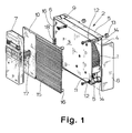
- FIG. 1 The basic principle of the teaching of the invention will first be explained with reference to FIG. 1. This is about a belt box around a roller shutter belt 1, which is indicated on the right in FIG. 1 within the belt box. Inside the belt box you can also see other parts of the drive mechanism that are not to be explained in detail. It is not necessarily a roller shutter belt in the true sense of the word, sometimes a tension steel belt, a pull chain or the like, which is preferably wound up inside the belt box, is sometimes used.
- the recognizable housing 2 is made of plastic in most cases, but is sometimes also partially made of metal or reinforced with metal. In principle, it has a front wall 3 located at the front in FIG. 1, a largely hidden rear wall 4 in FIG. 1 and side walls 5 and end walls 6 connecting the front wall 3 to the rear wall 4.
- An electrical drive motor not shown, is arranged in the housing 2 and drives a take-up spool, which is also not shown in more detail and carries the roller shutter belt 1, via a reduction gear, also not shown.
- This technique is known per se from the prior art; in this respect reference can be made to DE-A 3 214 235.
- a drive pinion is also possible as an alternative to the take-up spool if you only want to pull through, but do not necessarily want to take-up.
- an electrical switching control device 7 is arranged on the housing 2. As usual, this has control buttons, possibly also programming buttons, mostly also an electronic display device, etc. It can also, as shown in FIG. 2, be provided with an additional connection element 8, which is used, for example, to connect sun sensors, remote controls, etc.
- Fig. 1 an essential design feature of the belt box shown can be seen, namely that in an side wall 5 or end wall 6, here the upper side wall 5, an opening 9 is provided for entry of the roller shutter belt 1 in the housing 2.
- an opening 9 is provided for entry of the roller shutter belt 1 in the housing 2.
- the meaning of the only one opening 9 for teaching the invention has been explained in the general part of the description.
- housing 2 as in the prior art from which the invention is based, can optionally be pivotably suspended with an end wall or side wall if one wishes to implement this possibility known from the prior art.
- the teaching of the invention is now basically concerned with how the belt box can be attached to a fastening surface laterally. This often occurs when attached to a side wall next to a window or the like.
- the invention now teaches in a first alternative, shown in Fig. 1, that the housing 2 can be attached to a mounting surface both with the front wall 3 and with the rear wall 4, that the switching control device 7 as a separate component which can be removed from the housing 2 is carried out that on the housing 2, both on the front wall 3 and on the rear wall 4, an attachment area 10 is formed for the switching control device 7 and that the switching control device 7 optionally in one or the other mounting area 10 on the housing 2 mechanically attached and with the drive motor electrically control technology is connected or connectable.
- FIG. 1 The essential content of this teaching has been explained in the general part of the description, the mounting technology is shown in FIG. 1 without further notice.
- the housing 2 instead of as there with the rear wall 4 could easily be attached in reverse with the front wall 3 to a fastening surface.
- the switching control device 7 would be mounted on the rear wall 4 instead of on the front wall 3.
- Front and rear wall 3, 4 are therefore functionally and structurally the same, they can mutually take over the function of the other wall.
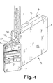
- FIG. 4 shows a second alternative for the teaching of the invention, which is characterized in that the housing 2 can be attached to a fastening surface both with the front wall 3 and with the rear wall 4 and that the switching control device 7 in or on an end wall 6 or side wall 5 is arranged and from there is also accessible in terms of operation.
- the illustrated embodiment of this slightly different, although realized with the same configuration of front and rear wall 3, 4 alternative is explained in detail below, at the moment it is about the fundamentally somewhat different design with arrangement of the switching control device 7 on the end wall 6th or assigned to the end wall 6.
- Fig. 1 shows a special measure, which is characterized in that the housing 2 is provided with through-openings 11 for fastening screws 12 extending between the front wall 3 and the rear wall 4 and the through-openings 11, preferably, at both ends with corresponding Receptacles for the screw heads of the fastening screws 12 are provided and that the housing 2 can be attached to a fastening surface by means of the fastening screws 12, possibly using spacers 13.
- the design of the housing 2 with push-through openings 11 extending from the front to the rear and correspondingly long fastening screws 12 has the advantage that, in order to attach the housing 2 in both possible positions, once with the front wall 3 once with the rear wall 4, the housing 2, as must be opened in the otherwise known prior art.
- the push-through openings 11 in cylindrical support channels 14 running in the housing 2 a stiffening and stabilizing construction which is particularly recommended when the housing 2 is made of plastic.
- the spacers 13 serve to ensure that the wall 3 or 4, which comes into contact with the fastening surface, is supported evenly in the case of a material which is sensitive to bending in the fastening region.
- the housing 2 shown in the drawing is flat-plate-like in all embodiments, as in the generic state of the art.
- the thickness of the housing essentially corresponds to the width of the roller shutter belt 1.
- this does not necessarily have to be the case for the teaching of the invention; a thicker housing 2 could also be designed according to the invention with the same advantage.
- Fig. 1 now shows a further preferred embodiment such that a removable panel 15 can be attached to the front wall 3 and the rear wall 4.
- the veneer 15 can be seen here as a plastic plate with an ornamentation or structuring for design reasons in the area on the right and the attachment area 10 for the switching control device 7 on the left. This is only one way of designing it. It is essential that the facing 15 covers a less beautiful surface design of the front wall 3 or the rear wall 4, which is necessary for fastening reasons, that is to say in any case the visible wall.
- the removable cover can be snapped onto the front wall 3; corresponding snap-in or plug-in shapes 16 can be seen.
- the cover 15 itself forms the attachment area 10 for the switching control device 7.
- the attachment area 10 is not touched by the cover 15, that is to say the cover 15 is made correspondingly small and / or has a recess for the attachment area 10. This latter version is indicated in FIGS. 2, 3 and 4, if it is assumed that a facing 15 is attached to the front wall 3 there.
- the component forming the switching control device 7 must now also me in some way mechanically attached to the housing. It can be screwed on and / or locked there, for example. This is not shown in detail in the drawing.
- the switching control device 7 is connected to the inside of the housing 2 by electrical control technology via a flexible connecting line 17, preferably designed as a ribbon cable.
- a flexible connecting line 17 preferably designed as a ribbon cable.
- FIGS. 1, 2 and 3 because of the implementation of the switching control device 7 required there that the switching control device 7 with the interior of the housing 2 electrically control technology via an electrical connector 18 and possibly a flexible, preferably as a ribbon cable executed connecting line 17 is connected or connectable.
- the version with a connecting cable 17 designed as a ribbon cable and, subsequently, a connector 18, which is only indicated on the housing 2 applies.
- the connector 18 realized in FIGS. 2 and 3 with a corresponding opposite position on the housing 2 not only leads to an electrical connection but also to a mechanical latching.
- the housing 2 is generally cuboid and the opening 9 is integrated in the side wall 5 of the housing 2 lying above. This does not necessarily have to be the case, as can be seen from FIGS. 2, 3 and 4, for which it applies that the housing 2 has a shoulder 19 or a step at the opening 9 and the attachment areas 10, if present, are arranged between end wall 6 or side wall 5 and shoulder 19.
- a step or a shoulder 19 in the housing 2 has not only design advantages, but in particular also technical advantages in that the introduction of the roller shutter belt 1 into the housing 2 via the opening 9 is particularly flexible. This is because the roller shutter belt 1 can be introduced into the housing 2 particularly comfortably in an angular range of approximately 90 ° or even a little more.
- FIG. 2 shows a shoulder 19 that opens up, but which in the inner area is actually converted into a recessed shoulder 19 by the recess 20 realized there.
- the recess 20 can also be realized with a contour of the housing 2 without an outer shoulder 19, so that also a housing of the outer shape as shown in FIG. 1, a recess 19 could be created inside through the recess 20.
- roller shutter belt 1 can be guided out of the housing 2 in different directions.
- the housing 2 itself can of course also be attached to a fastening surface in different orientations. If there is an opening 9 for the roller shutter belt 1, it will generally be limited to an angular range of 90. This requirement corresponds to the embodiment of the invention according to a preferred embodiment, not shown, in which the switching control device 7 can be attached to the housing 2 in different orientations, preferably in two positions offset from one another.
- the exemplary embodiment of a belt box according to the invention shown in FIG. 4 has already been mentioned above.
- This exemplary embodiment is now characterized in detail by the fact that the switching control device 7 is designed as a separate component which can be removed from the housing 2, and that the front wall 6 or side wall 5 carrying the switching control device 7 is not opposite the plane of the rear wall 4 or front wall 3 is oriented vertically, but inclined, and that the inclined end wall 6 or side wall 5 is wholly or partly formed by a removable support bracket 21 having a corresponding wedge angle.
- an inclination angle or wedge angle of 45 ° is realized, but basically there is a wide range of inclination angles, primarily between 30 and 600.
- FIG. 4 shows the switching control device 7 on the same end wall 6, which also suggests the opening 9 for the roller shutter belt 1.
- This has the advantage that the other end wall 6 can be designed to be openable.
Landscapes
- Engineering & Computer Science (AREA)
- Structural Engineering (AREA)
- Architecture (AREA)
- Civil Engineering (AREA)
- Operating, Guiding And Securing Of Roll- Type Closing Members (AREA)
- Power-Operated Mechanisms For Wings (AREA)
- Blinds (AREA)
- Spinning Or Twisting Of Yarns (AREA)
- Details Of Rigid Or Semi-Rigid Containers (AREA)
Applications Claiming Priority (2)
| Application Number | Priority Date | Filing Date | Title |
|---|---|---|---|
| DE9106033U | 1991-05-16 | ||
| DE9106033U DE9106033U1 (de) | 1991-05-16 | 1991-05-16 | Gurtkasten für einen Rolladengurt oder ein ähnliches Zugelement |
Publications (3)
| Publication Number | Publication Date |
|---|---|
| EP0513794A2 true EP0513794A2 (fr) | 1992-11-19 |
| EP0513794A3 EP0513794A3 (en) | 1993-03-31 |
| EP0513794B1 EP0513794B1 (fr) | 1994-11-09 |
Family
ID=6867359
Family Applications (1)
| Application Number | Title | Priority Date | Filing Date |
|---|---|---|---|
| EP92108165A Expired - Lifetime EP0513794B1 (fr) | 1991-05-16 | 1992-05-14 | Boîte pour la sangle d'un volet roulant ou élément de traction similaire |
Country Status (3)
| Country | Link |
|---|---|
| EP (1) | EP0513794B1 (fr) |
| AT (1) | ATE114018T1 (fr) |
| DE (2) | DE9106033U1 (fr) |
Cited By (3)
| Publication number | Priority date | Publication date | Assignee | Title |
|---|---|---|---|---|
| WO2004015235A1 (fr) * | 2002-08-07 | 2004-02-19 | Jolly Motor Internatonal S.P.A. | Dispositif de commande a carte electronique interchangeable pour elements roulants tels qu'ecrans-rouleaux, volets roulants, stores et analogues |
| DE202007009183U1 (de) * | 2007-04-25 | 2008-09-04 | Arca Beteiligungen Gmbh | Gurtwickler für eine Verdunkelungsvorrichtung wie einen Rolladen o.dgl. |
| EP1985792A3 (fr) * | 2007-04-25 | 2009-02-18 | ARCA Beteiligungen GmbH | Enrouleur de sangle pour un volet roulant |
Families Citing this family (7)
| Publication number | Priority date | Publication date | Assignee | Title |
|---|---|---|---|---|
| DE4420980C2 (de) * | 1994-06-16 | 1997-12-04 | Bosch Gmbh Robert | Elektrische Antriebsvorrichtung für Zugorgane, insbesondere für einen Gurt eines Rolladens |
| DE29622535U1 (de) * | 1996-12-30 | 1998-04-23 | Robert Bosch Gmbh, 70469 Stuttgart | Elektrische Antriebsvorrichtung für einen Gurt eines Rolladens |
| DE19837267A1 (de) * | 1998-08-17 | 2000-02-24 | Bosch Gmbh Robert | Elektrische Antriebsvorrichtung für Verdunkelungs- oder Beschattungsvorrichtungen |
| DE29921653U1 (de) * | 1999-10-06 | 2001-02-15 | Rademacher, Wilhelm, 46414 Rhede | Gurtwickler für einen Rolladengurt o.dgl. |
| DE102004012354C5 (de) * | 2003-03-11 | 2010-09-30 | Provita Verwaltung Gmbh | Elektrischer Gurtwickler |
| EP2104196A3 (fr) | 2008-03-20 | 2012-01-11 | ProVita Verwaltung GmbH | Dispositif de commande d'un entraînement électrique pour un dispositif d'obscurcissement |
| DE102011085100A1 (de) * | 2011-10-24 | 2013-04-25 | Alfred Schellenberg Gmbh | Gurtwickler für das Gurtband o.dgl. Zugelement einer Verdunkelungsvorrichtung, insbesondere eines Rollladens o.dgl. |
Family Cites Families (6)
| Publication number | Priority date | Publication date | Assignee | Title |
|---|---|---|---|---|
| DE6940282U (de) * | 1969-10-16 | 1971-05-06 | Maltusch Harry | Universalkastenwickler mit drehbarem einsteckhalter |
| DE3214235C2 (de) * | 1982-04-17 | 1989-06-08 | Willi 4292 Rhede Rademacher | Gurtkasten für eine Verdunkelungsvorrichtung |
| DE3304962C2 (de) * | 1983-02-12 | 1986-04-10 | Willi 4292 Rhede Rademacher | Verdunkelungsvorrichtung |
| ATE62319T1 (de) * | 1987-07-09 | 1991-04-15 | Willi Rademacher | Antriebseinheit fuer einen lamellenvorhang od. dgl. |
| CA2004866C (fr) * | 1989-12-21 | 1994-03-01 | Nien Ming | Dispositif de commande manuelle/automatique, a fixer, a double usage, pour stores venitiens |
| DE4008939A1 (de) * | 1990-03-20 | 1991-09-26 | Elero Antrieb Sonnenschutz | Elektronische rolladensteuerung mit steckbarem steuerteil |
-
1991
- 1991-05-16 DE DE9106033U patent/DE9106033U1/de not_active Expired - Lifetime
-
1992
- 1992-05-14 AT AT92108165T patent/ATE114018T1/de not_active IP Right Cessation
- 1992-05-14 DE DE59200759T patent/DE59200759D1/de not_active Expired - Fee Related
- 1992-05-14 EP EP92108165A patent/EP0513794B1/fr not_active Expired - Lifetime
Cited By (3)
| Publication number | Priority date | Publication date | Assignee | Title |
|---|---|---|---|---|
| WO2004015235A1 (fr) * | 2002-08-07 | 2004-02-19 | Jolly Motor Internatonal S.P.A. | Dispositif de commande a carte electronique interchangeable pour elements roulants tels qu'ecrans-rouleaux, volets roulants, stores et analogues |
| DE202007009183U1 (de) * | 2007-04-25 | 2008-09-04 | Arca Beteiligungen Gmbh | Gurtwickler für eine Verdunkelungsvorrichtung wie einen Rolladen o.dgl. |
| EP1985792A3 (fr) * | 2007-04-25 | 2009-02-18 | ARCA Beteiligungen GmbH | Enrouleur de sangle pour un volet roulant |
Also Published As
| Publication number | Publication date |
|---|---|
| EP0513794B1 (fr) | 1994-11-09 |
| DE9106033U1 (de) | 1992-09-17 |
| ATE114018T1 (de) | 1994-11-15 |
| EP0513794A3 (en) | 1993-03-31 |
| DE59200759D1 (de) | 1994-12-15 |
Similar Documents
| Publication | Publication Date | Title |
|---|---|---|
| EP0092118B1 (fr) | Caisson pour sangle de dispositif d'assombrissement | |
| EP0298217B1 (fr) | Unité de commande pour store à lamelles ou similaires | |
| EP0513794B1 (fr) | Boîte pour la sangle d'un volet roulant ou élément de traction similaire | |
| DE4008939A1 (de) | Elektronische rolladensteuerung mit steckbarem steuerteil | |
| EP0924379A2 (fr) | Enrouleur de sangle pour un dispositif d'occultation | |
| EP3483375A1 (fr) | Dispositif d'actionnement, au moins partiellement automatique, d'un vantail de porte | |
| EP0853713B1 (fr) | Glissiere | |
| DE102004012354B4 (de) | Elektrischer Gurtwickler | |
| AT410354B (de) | Elektrische antriebsvorrichtung für verdunkelungs- oder beschattungsvorrichtung | |
| DE3415551A1 (de) | Rolladen fuer dachfenster | |
| EP0740045B1 (fr) | Caisson pour volet roulant | |
| DE102012003696A1 (de) | Gurtwickler für eine Verdunkelungsvorrichtung wie einen Rolladen o. dgl. | |
| EP0341529A2 (fr) | Serrure | |
| DE19531040A1 (de) | Schutzvorrichtung für Bauelemente wie Fenster, Türen oder dergleichen | |
| EP1762677A2 (fr) | Dispositif d'ouverture de porte | |
| EP1985792A2 (fr) | Enrouleur de sangle pour un volet roulant | |
| EP1567739A2 (fr) | Portiere de vehicule automobile | |
| EP4467760B1 (fr) | Entraînement pour un battant | |
| DE2515983A1 (de) | Elektroantrieb fuer fensteroeffner u.dgl. | |
| DE10301014B4 (de) | Elektronisches Steuergerät | |
| EP1466066B1 (fr) | Systeme d'entrainement de volet roulant de construction compacte | |
| EP0109066B1 (fr) | Commande pour volets roulants | |
| DE3015104C2 (de) | Treibstangenantrieb in einem Treibstangenschloß | |
| EP0150000A2 (fr) | Dispositif de manoeuvre de volet roulant comme système modulaire pour commande à gland, à manivelle et électrique | |
| EP0844356A1 (fr) | Dispositif pour la commande d'une fenêtre |
Legal Events
| Date | Code | Title | Description |
|---|---|---|---|
| PUAI | Public reference made under article 153(3) epc to a published international application that has entered the european phase |
Free format text: ORIGINAL CODE: 0009012 |
|
| AK | Designated contracting states |
Kind code of ref document: A2 Designated state(s): AT BE CH DE FR IT LI LU NL |
|
| PUAL | Search report despatched |
Free format text: ORIGINAL CODE: 0009013 |
|
| AK | Designated contracting states |
Kind code of ref document: A3 Designated state(s): AT BE CH DE FR IT LI LU NL |
|
| 17P | Request for examination filed |
Effective date: 19930416 |
|
| 17Q | First examination report despatched |
Effective date: 19931102 |
|
| GRAA | (expected) grant |
Free format text: ORIGINAL CODE: 0009210 |
|
| AK | Designated contracting states |
Kind code of ref document: B1 Designated state(s): AT BE CH DE FR IT LI LU NL |
|
| REF | Corresponds to: |
Ref document number: 114018 Country of ref document: AT Date of ref document: 19941115 Kind code of ref document: T |
|
| REF | Corresponds to: |
Ref document number: 59200759 Country of ref document: DE Date of ref document: 19941215 |
|
| ITF | It: translation for a ep patent filed | ||
| ET | Fr: translation filed | ||
| PLBE | No opposition filed within time limit |
Free format text: ORIGINAL CODE: 0009261 |
|
| STAA | Information on the status of an ep patent application or granted ep patent |
Free format text: STATUS: NO OPPOSITION FILED WITHIN TIME LIMIT |
|
| 26N | No opposition filed | ||
| PGFP | Annual fee paid to national office [announced via postgrant information from national office to epo] |
Ref country code: LU Payment date: 19960501 Year of fee payment: 5 |
|
| PGFP | Annual fee paid to national office [announced via postgrant information from national office to epo] |
Ref country code: BE Payment date: 19960513 Year of fee payment: 5 |
|
| PGFP | Annual fee paid to national office [announced via postgrant information from national office to epo] |
Ref country code: FR Payment date: 19960515 Year of fee payment: 5 |
|
| PGFP | Annual fee paid to national office [announced via postgrant information from national office to epo] |
Ref country code: AT Payment date: 19960520 Year of fee payment: 5 |
|
| PGFP | Annual fee paid to national office [announced via postgrant information from national office to epo] |
Ref country code: CH Payment date: 19960524 Year of fee payment: 5 |
|
| PGFP | Annual fee paid to national office [announced via postgrant information from national office to epo] |
Ref country code: NL Payment date: 19960531 Year of fee payment: 5 |
|
| PGFP | Annual fee paid to national office [announced via postgrant information from national office to epo] |
Ref country code: DE Payment date: 19960727 Year of fee payment: 5 |
|
| PG25 | Lapsed in a contracting state [announced via postgrant information from national office to epo] |
Ref country code: LU Free format text: LAPSE BECAUSE OF NON-PAYMENT OF DUE FEES Effective date: 19970514 Ref country code: AT Effective date: 19970514 |
|
| PG25 | Lapsed in a contracting state [announced via postgrant information from national office to epo] |
Ref country code: LI Free format text: LAPSE BECAUSE OF NON-PAYMENT OF DUE FEES Effective date: 19970531 Ref country code: CH Free format text: LAPSE BECAUSE OF NON-PAYMENT OF DUE FEES Effective date: 19970531 Ref country code: BE Effective date: 19970531 |
|
| BERE | Be: lapsed |
Owner name: RADEMACHER WILHELM Effective date: 19970531 |
|
| PG25 | Lapsed in a contracting state [announced via postgrant information from national office to epo] |
Ref country code: NL Effective date: 19971201 |
|
| REG | Reference to a national code |
Ref country code: CH Ref legal event code: PL |
|
| PG25 | Lapsed in a contracting state [announced via postgrant information from national office to epo] |
Ref country code: FR Free format text: LAPSE BECAUSE OF NON-PAYMENT OF DUE FEES Effective date: 19980130 |
|
| NLV4 | Nl: lapsed or anulled due to non-payment of the annual fee |
Effective date: 19971201 |
|
| PG25 | Lapsed in a contracting state [announced via postgrant information from national office to epo] |
Ref country code: DE Free format text: LAPSE BECAUSE OF NON-PAYMENT OF DUE FEES Effective date: 19980203 |
|
| REG | Reference to a national code |
Ref country code: FR Ref legal event code: ST |
|
| PG25 | Lapsed in a contracting state [announced via postgrant information from national office to epo] |
Ref country code: IT Free format text: LAPSE BECAUSE OF NON-PAYMENT OF DUE FEES;WARNING: LAPSES OF ITALIAN PATENTS WITH EFFECTIVE DATE BEFORE 2007 MAY HAVE OCCURRED AT ANY TIME BEFORE 2007. THE CORRECT EFFECTIVE DATE MAY BE DIFFERENT FROM THE ONE RECORDED. Effective date: 20050514 |