EP0514026A2 - Ceinture haémostatique à pression - Google Patents
Ceinture haémostatique à pression Download PDFInfo
- Publication number
- EP0514026A2 EP0514026A2 EP92303593A EP92303593A EP0514026A2 EP 0514026 A2 EP0514026 A2 EP 0514026A2 EP 92303593 A EP92303593 A EP 92303593A EP 92303593 A EP92303593 A EP 92303593A EP 0514026 A2 EP0514026 A2 EP 0514026A2
- Authority
- EP
- European Patent Office
- Prior art keywords
- strip
- compressive
- set forth
- bag
- hemostatic belt
- Prior art date
- Legal status (The legal status is an assumption and is not a legal conclusion. Google has not performed a legal analysis and makes no representation as to the accuracy of the status listed.)
- Granted
Links
- 229940030225 antihemorrhagics Drugs 0.000 title 1
- 230000000025 haemostatic effect Effects 0.000 title 1
- 230000002439 hemostatic effect Effects 0.000 claims abstract description 68
- 239000004744 fabric Substances 0.000 claims abstract description 35
- 239000012530 fluid Substances 0.000 claims abstract description 25
- 239000004753 textile Substances 0.000 claims abstract description 18
- 230000000740 bleeding effect Effects 0.000 claims abstract description 17
- 230000003014 reinforcing effect Effects 0.000 claims description 18
- 229920001971 elastomer Polymers 0.000 claims description 17
- 239000000463 material Substances 0.000 claims description 5
- 206010052428 Wound Diseases 0.000 description 50
- 208000027418 Wounds and injury Diseases 0.000 description 50
- 238000003780 insertion Methods 0.000 description 45
- 230000037431 insertion Effects 0.000 description 45
- 239000004576 sand Substances 0.000 description 8
- 239000000835 fiber Substances 0.000 description 7
- 239000011505 plaster Substances 0.000 description 7
- 230000037303 wrinkles Effects 0.000 description 7
- 230000006835 compression Effects 0.000 description 5
- 238000007906 compression Methods 0.000 description 5
- 239000007789 gas Substances 0.000 description 5
- 239000007788 liquid Substances 0.000 description 5
- 239000000853 adhesive Substances 0.000 description 4
- 238000000605 extraction Methods 0.000 description 4
- 239000004835 fabric adhesive Substances 0.000 description 4
- 238000000034 method Methods 0.000 description 4
- 229920003002 synthetic resin Polymers 0.000 description 4
- 239000000057 synthetic resin Substances 0.000 description 4
- 201000004624 Dermatitis Diseases 0.000 description 3
- 208000003251 Pruritus Diseases 0.000 description 3
- 230000001070 adhesive effect Effects 0.000 description 3
- 210000001105 femoral artery Anatomy 0.000 description 3
- 210000003191 femoral vein Anatomy 0.000 description 3
- 230000001965 increasing effect Effects 0.000 description 3
- 210000003141 lower extremity Anatomy 0.000 description 3
- -1 polyethylene terephthalate Polymers 0.000 description 3
- 229920000139 polyethylene terephthalate Polymers 0.000 description 3
- 239000005020 polyethylene terephthalate Substances 0.000 description 3
- 238000009958 sewing Methods 0.000 description 3
- IJGRMHOSHXDMSA-UHFFFAOYSA-N Atomic nitrogen Chemical compound N#N IJGRMHOSHXDMSA-UHFFFAOYSA-N 0.000 description 2
- CURLTUGMZLYLDI-UHFFFAOYSA-N Carbon dioxide Chemical compound O=C=O CURLTUGMZLYLDI-UHFFFAOYSA-N 0.000 description 2
- 238000011161 development Methods 0.000 description 2
- 229910001873 dinitrogen Inorganic materials 0.000 description 2
- 239000000499 gel Substances 0.000 description 2
- 238000002347 injection Methods 0.000 description 2
- 239000007924 injection Substances 0.000 description 2
- 210000000689 upper leg Anatomy 0.000 description 2
- 239000002759 woven fabric Substances 0.000 description 2
- OEPOKWHJYJXUGD-UHFFFAOYSA-N 2-(3-phenylmethoxyphenyl)-1,3-thiazole-4-carbaldehyde Chemical compound O=CC1=CSC(C=2C=C(OCC=3C=CC=CC=3)C=CC=2)=N1 OEPOKWHJYJXUGD-UHFFFAOYSA-N 0.000 description 1
- 208000035473 Communicable disease Diseases 0.000 description 1
- 229920000742 Cotton Polymers 0.000 description 1
- 208000010201 Exanthema Diseases 0.000 description 1
- JHWNWJKBPDFINM-UHFFFAOYSA-N Laurolactam Chemical compound O=C1CCCCCCCCCCCN1 JHWNWJKBPDFINM-UHFFFAOYSA-N 0.000 description 1
- 229920000299 Nylon 12 Polymers 0.000 description 1
- 229920002292 Nylon 6 Polymers 0.000 description 1
- 229920002302 Nylon 6,6 Polymers 0.000 description 1
- 239000004952 Polyamide Substances 0.000 description 1
- 239000004698 Polyethylene Substances 0.000 description 1
- BZHJMEDXRYGGRV-UHFFFAOYSA-N Vinyl chloride Chemical compound ClC=C BZHJMEDXRYGGRV-UHFFFAOYSA-N 0.000 description 1
- 239000008280 blood Substances 0.000 description 1
- 210000004369 blood Anatomy 0.000 description 1
- 210000004204 blood vessel Anatomy 0.000 description 1
- 239000001569 carbon dioxide Substances 0.000 description 1
- 229910002092 carbon dioxide Inorganic materials 0.000 description 1
- 230000000747 cardiac effect Effects 0.000 description 1
- 230000002490 cerebral effect Effects 0.000 description 1
- 239000002131 composite material Substances 0.000 description 1
- 238000010276 construction Methods 0.000 description 1
- 239000002872 contrast media Substances 0.000 description 1
- 238000007796 conventional method Methods 0.000 description 1
- 238000013461 design Methods 0.000 description 1
- 238000003745 diagnosis Methods 0.000 description 1
- 201000010099 disease Diseases 0.000 description 1
- 208000037265 diseases, disorders, signs and symptoms Diseases 0.000 description 1
- 235000012489 doughnuts Nutrition 0.000 description 1
- 229940079593 drug Drugs 0.000 description 1
- 239000003814 drug Substances 0.000 description 1
- 230000000694 effects Effects 0.000 description 1
- 210000004177 elastic tissue Anatomy 0.000 description 1
- 230000002708 enhancing effect Effects 0.000 description 1
- 201000005884 exanthem Diseases 0.000 description 1
- 239000010985 leather Substances 0.000 description 1
- 238000004519 manufacturing process Methods 0.000 description 1
- 239000004745 nonwoven fabric Substances 0.000 description 1
- 229920002647 polyamide Polymers 0.000 description 1
- 229920000728 polyester Polymers 0.000 description 1
- 229920000573 polyethylene Polymers 0.000 description 1
- 238000011205 postoperative examination Methods 0.000 description 1
- 230000001737 promoting effect Effects 0.000 description 1
- 206010037844 rash Diseases 0.000 description 1
- 230000003252 repetitive effect Effects 0.000 description 1
- 239000012815 thermoplastic material Substances 0.000 description 1
- 125000000391 vinyl group Chemical group [H]C([*])=C([H])[H] 0.000 description 1
- 229920002554 vinyl polymer Polymers 0.000 description 1
- 238000003466 welding Methods 0.000 description 1
Images



Classifications
-
- A—HUMAN NECESSITIES
- A61—MEDICAL OR VETERINARY SCIENCE; HYGIENE
- A61B—DIAGNOSIS; SURGERY; IDENTIFICATION
- A61B17/00—Surgical instruments, devices or methods
- A61B17/12—Surgical instruments, devices or methods for ligaturing or otherwise compressing tubular parts of the body, e.g. blood vessels or umbilical cord
- A61B17/132—Tourniquets
- A61B17/135—Tourniquets inflatable
-
- A—HUMAN NECESSITIES
- A61—MEDICAL OR VETERINARY SCIENCE; HYGIENE
- A61B—DIAGNOSIS; SURGERY; IDENTIFICATION
- A61B17/00—Surgical instruments, devices or methods
- A61B17/12—Surgical instruments, devices or methods for ligaturing or otherwise compressing tubular parts of the body, e.g. blood vessels or umbilical cord
- A61B17/132—Tourniquets
- A61B17/1322—Tourniquets comprising a flexible encircling member
- A61B17/1325—Tourniquets comprising a flexible encircling member with means for applying local pressure
Definitions
- the present invention relates to a compressive hemostatic belt used to stop bleeding from a catheter Insertion wound upon completion of an arterial catheter examination.
- Cardiac catheter examinations are made by surgical operation in a few cases but in most cases by the so-called catheter puncture method which moves a catheter from the femoral artery or vein in the inguinal region to the heart.
- a contrast medium or various medicines are injected through the catheter puncturing the femoral artery or vein in the inguinal region or various preoperative and postoperative examinations are conducted.
- the sand bag tends to slip off when the patient lying on his back tilts his body even slightly, and such deviation of the sand bag results in the sand bag deviating form the compressed area, making the hemostatic effect imperfect, leading to other drawbacks, such as ecchymona.
- Japanese Patent Application Disclosure No. 92746/1985 or Japanese Patent Application Disclosure No. 198139/1985 suggests a compressive hemostatic belt formed of stretch fabric as means for compressive hemostatic means for catheter insertion wounds to replace the adhesive plaster and sand bag.
- Such compressive hemostatic belt is constructed to make it difficult for a user to wrap it and to visually ascertain the level of its compressive force on the catheter insertion wound and makes it necessary for him to rewrap it when adjusting the compressive force; thus, the loading state of the belt is unstable.
- the belt uses an expensive stretch textile fabric, its production cost is very high, making it difficult to throw it after use when there is a hygienic problem of causing infectious diseases due to adhesion of blood. Therefore, to prevent such hemoinfectious diseases, after each use of such compressive hemostatic belt, it has to be washed and sterilized, imposing limitations not only from a hygienic standpoint but also from the standpoint of enhancing labor saving for nurses.
- the present invention provides a compressive hemostatic belt comprising a strip of nonstretch or low-stretch fabric, and a bag adapted to be expanded by being filled with fluid, said bag being attached to said strip at a predetermined position thereon.
- the bag attached to the strip at the predetermined position has a pump and a pressure gage connected thereto through a check valve, and operator operates the pump while watching the pressure gage to fill the bag with fluid to expand said bag so as to compress an area where bleeding is to be stopped. Since a nonstretch or low-stretch textile fabric is used for the strip, the development of a stiffening feel, pain or itch can be avoided and dermatitis or bubbles are prevented.
- the use of the bag which is expanded by being filled with fluid as compressing means provides a narrower range of compression, ensuring a hemostatic function for compressing only a catheter insertion wound while causing almost no compressive feeling to be transmitted to the other areas.
- the pressurizing mechanism is constructed by connecting, through a check valve, a pump and a pressure gage to the bag which is expansible by being filled with fluid, it is possible to adjust the compressive force to be applied to a catheter insertion wound and to maintain such adjusted force for a long time by the check valve.
- compressing and fixing are simultaneously effected by the bag which is expansible by being fixed with fluid, there is provided a compressive hemostatic belt whose operability is satisfactory and which does not require a sand bag or the like and is compact and easy to carry about.
- the components other than the pump and pressure gage are much cheaper than conventional parts, allowing the belt to be thrown away once it has been used; thus, noteworthy effects from the standpoint of improving health control and promoting labor saving are attained.
- a rigid case for preventing the bag from expanding to the side opposite to the area where bleeding it to be stopped may be installed, if necessary, between the bag and the strip, said rigid case having an inner flange around its open end to surround said bag or balloon.
- the inner flange of said rigid case may be a separate body with the intended compression area cut out in doughnut form and may be attached to the open end of said rigid case.
- the balloon With the inner flange formed around the open end of the rigid case to surround the balloon, the balloon can be reliably expanded to the area where bleeding is to be stopped while the inner flange of the rigid case prevents the balloon from deviating outside. Therefore, there is no possibility of the bag from deviating from the predetermined position and said area can be positively compressed by the bag to provide a perfect hemostatic effect. Further, if the inner flange of the rigid case is a separate body with the compressive area cut out to suit the affected area where bleeding is to be stopped and is attached to the open end of said rigid case, doughnut-shaped inner flanges with various compressive areas cut out may be prepared, making it possible to adjust the compressive area and to prevent stagnation otherwise caused by wide area compression.
- Another object of the invention is to provide a compressive hemostatic belt which does not develop wrinkles when applied and which is capable of exerting a stabilized compressive force.
- the invention attaches a reinforcing sheet to the portion of the strip which covers the area of the body extending from the waist to the hip when the belt is applied.
- the reinforcing sheet is preferably 10 - 90 cm long and is placed laterally of the pocket of the strip.
- the provision of the reinforcing sheet on the portion of the strip which covers the area of the patient's body extending from the waist to the hip prevents wrinkles or kinks from being developed in this portion when the strip is wrapped, and the strip can be reliably wrapped without having to exert a very great force; thus, a degree of tightening which is suited to the patient can be obtained.
- the wound can be reliably compressed and there is no possibility of giving the patient an unpleasant feeling due to kinks or the like. Further, since the force required for wrapping is not so great, the labor of nurses or the like for installing the belt can be reduced and stagnation and ecchymona due to greater compression than necessary can be avoided.
- Figs. 1 and 2 show a compressive hemostatic belt according to an embodiment of the invention.
- the numeral 1 denotes a strip made of a nonstretch or low-stretch textile fabric formed with a pocket 3 by sewing a pocket fabric 2 in the form of a stretch textile fabric thereto at a predetermined position.
- the numeral 4 denotes a rigid case which is a bowel-shaped rigid member made of synthetic resin or the like, said rigid case being received in the pocket 3 of the strip 1 with its open side directed to the pocket fabric 2.
- the numeral 5 denotes a bag which can be expanded by being filled with a suitable fluid (a gas, such as air or nitrogen gas or a liquid including a gel), for example, a balloon made of rubber, received in the pocket 3 of the strip 1 through the rigid case 4, with a fluid feed tube 7 projecting outward and having a check valve 6.
- a suitable fluid a gas, such as air or nitrogen gas or a liquid including a gel
- the fluid feed tube 7 of the balloon 5 has a manually operable pump 8 and a pressure gage 9 connected thereto.
- gauze 10 is placed on a catheter insertion wound A after extraction of the catheter, and then the belt is placed thereon such that the pocket fabric 2 of the pocket 3 receiving the balloon 5 is directed to the gauze 10. Then, for example, as shown in Fig. 4, the strip 1 is wrapped around the waist of the patient more than one turn, the end being fixed in place by utilizing fixing means, such as adhesive plaster.
- the manually operable pump 8 and pressure gage 9 are connected to the fluid feed tube 7 of the balloon 5 and the pump 8 is operated while watching the pressure gage 9, so as to fill the balloon 5 with the fluid, thereby expanding the balloon 5 toward the catheter insertion wound A with the rigid case 4 preventing the balloon 5 from expanding toward the side opposite to the catheter insertion wound A , whereby the catheter insertion wound A is compressed through the gauze 10 and at the same time the strip 1 is firmly secured to the patient.
- the strip 1 is described as formed of a nonstretch textile fabric, but it may be formed of a low-stretch textile fabric, an the pocket 3 is described as formed by sewing a fabric 2 which is a stretch textile fabric, it may be formed by fabricating the strip 1 in bag form to provide a pocket 3 at a predetermined position to receive the rigid case 4 and balloon 5 therein.
- the strip 1 is fabricated in bag form using a nonstretch or low-stretch textile fabric, as described above, the compressive force exerted by the expansion of the balloon 5 on the catheter insertion wound A is sufficient. If, however, the surface of the pocket 3 of the strip 1 receiving the balloon 5 opposite to the catheter insertion wound A made of stretch fiber, the compressive force on the catheter insertion wound A can be increased.
- the balloon 5 is received in the pocket 3 of the strip 1 through the rigid case 4 for preventing the expansion of the balloon 5 toward the side opposite to the catheter insertion wound A .
- the balloon 5 may be received naked in the pocket 3 of the strip 1.
- the balloon 5 can be expanded toward the catheter insertion wound A while the strip 1 prevents it from expanding toward the side opposite to the catheter insertion wound A .
- the liquid When the balloon 5 is expanded with liquid, as compared with the case of expanding it with gas, the liquid less tends to leak through the balloon 5 and the check valve 6 attached thereto, and even if it leaks, the leakage can be more easily detected and the compressive force can be maintained at a constant value.
- the strip 1 is wound at right angles with the body axis; however, the invention is not limited thereto. Besides the wrapping method shown in Fig. 4, the strip 1 may be wrapped X-wise as shown in Fig. 12.
- the catheter insertion wound A can be compressed by utilizing the expansion of the balloon 5 as described above, the catheter insertion wound A alone can be compressed, with almost no compressed feeling transmitted to the other areas.
- rubber may be replaced by hardly fluid-permeable materials which are soft at ordinary temperature, including thermoplastic materials, such as polyethylene terephthalate, soft vinyl chloride, vinylidene chloride, nylon 6, nylon 6-6 and nylon 12, and composite materials such as polyethylene terephthalate and polyethylene.
- thermoplastic materials such as polyethylene terephthalate, soft vinyl chloride, vinylidene chloride, nylon 6, nylon 6-6 and nylon 12, and composite materials such as polyethylene terephthalate and polyethylene.
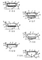
- Figs. 6 and 7 show an embodiment using a bag 11 made of a hardly fluid-permeable material which is soft at ordinary temperature, other than rubber.
- the bag 11 is in the form of bellows which can be expanded by being filled with fluid and as shown in Fig. 6 said bag 11 is received in its folded state in the pocket 3 of the strip 1 through the rigid case 4.
- the bag 11 is expanded as shown in Fig. 7 to compress the catheter insertion wound A through the gauze 10.
- the rigid case 4 and the bag 11 are separately formed, but they may be integrally formed.
- the bag 11 is received in the pocket 3 of the strip 1 through the rigid case 4 so as to prevent the bag from expanding toward the side opposite to the catheter insertion wound A ; however, as shown in Fig. 8, even if the bag 11 is received naked in the pocket 3 of the strip 1 without the rigid case 4 intervening therebetween, the bag 11 is prevented from expanding toward the side opposite to the catheter insertion wound A since the strip 1 is a nonstretch or low-stretch textile fabric. Thus, as shown in Fig. 9, the bag 11 is allowed to expand only toward the catheter insertion wound A , exerting a sufficient compressive force to compress the catheter insertion wound A . Thus, the bag 11 may be received in the pocket 3 of the strip 1 through the rigid case 4 as the need arises.
- a stretch textile fabric is used for the pocket fabric 2 forming the pocket 3 in the strip 1; however, the pocket fabric 2 may be a nonstretch or low-stretch textile fabric provided that the pocket 3 is formed large enough to allow the balloon 5 or bag 11 received therein to expand freely.
- the pocket 3 may be formed with an opening 12 to expose the balloon 12. If the pocket 3 is formed with such opening 12, as shown in Fig. 11 it is possible to allow the balloon 5 to expand such that it partly projects through the opening 12, thereby increasing the compressive force on the catheter insertion wound A .
- the balloon 5 or bag 12 is received in the pocket 3 of the strip 1 to thereby attach the balloon 5 or bag 11 of the strip 1; however, the balloon 5 or bag 11 may be attached to the strip 1 at a predetermined position by fastening means such as an adhesive agent or fastener.
- a compressive hemostatic belt 31 comprises a bag-like strip 21 formed of a knit fabric, woven fabric or nonwoven fabric of nonstretch fiber, such as cotton or polyester or nonstretch or low-stretch fiber, such as polyamide, a rubber balloon 22 inserted in a pocket 21a formed at a predetermined position on said strip 21 through a bowl 28 of synthetic resin, said two members forming compressive means for an area where bleeding is to be stopped, e.g., a catheter insertion wound.
- the strip 21 may be formed in its entirety of a knit fabric or woven fabric of nonstretch or low-stretch fiber or may have its portion opposed to the catheter insertion wound 30 made of stretch fiber, e.g.
- LIKURA (phonetically) (elastic fiber produced by Du pont de Nemours & Co.). If the portion opposed to the catheter insertion wound 30 is made of stretch fiber as described above, the rubber balloon 22 can be expanded more easily than when the whole of the strip 21 is made of nonstretch fiber, and the compressive force on the insertion wound 30 is further increased.
- the rubber balloon 22 may be received in the pocket 21a of the strip 21 with the check valve 24 exposed, and in order the prevent the rubber balloon 22 from expanding toward the side opposite to the insertion wound 30, as shown in Fig. 14 it may be received in the pocket 21a of the strip 21 through a bowl 28 made of synthetic resin.
- a manually operable air pump 25 and a pressure gage 26 are connected through said check valve 24 to the air feed tube 23 leading to the rubber balloon 22.
- the pressure in the rubber balloon 22 is maintained at a value suitable for compressing the insertion wound 30 for a predetermined period of time.
- An automatic pressure control system using a computer may be employed as the need arises.
- Gauze 29 is placed on the insertion wound 30 subsequently to extraction of the catheter and the compressive hemostatic belt is wrapped thereon. That is, the pocket 21a of the strip 21 having the balloon 22 received therein is placed on the insertion wound 30, and the strip 21 is passed from the inguinal region of the lower limb over the outer side, back side and inner side of the thigh and from the crotch over the front side of the thigh and crossed X-wise on the inguinal region, the remaining portion being wrapped in one or more layers around the trunk, the remaining portion of the strip 21 of the strip 21 being fixed in position by fixing means such as directionless fabric fasteners 27A and 27B. Thereafter, the air pump 25 is operated while watching the pressure gage 26 to expand the rubber balloon 22, as shown in Fig.
- Figs. 17 through 19 show another embodiment of the invention which is the same as the compressive hemostatic belt of Figs. 1 through 5 except the following, and like reference characters are applied to like parts to omit a repetitive description thereof.
- the compressive hemostatic belt of the invention is characterized in that the bowl shaped of the rigid case 4 is modified to provide a flat pot adapted to hold the balloon 5 and having an inner flange 4a formed thereon at the opening to prevent the balloon from sticking out.
- the bowl shaped of the rigid case 4 is modified to provide a flat pot adapted to hold the balloon 5 and having an inner flange 4a formed thereon at the opening to prevent the balloon from sticking out.
- the inner flange 4a of the rigid case 4 is integrally formed, but the invention is not limited thereto and as shown in Fig. 20 the inner flange 4a may be a doughnut-shaped separate part having its compressive area cut out and may be attached to the open end by suitable attaching means such as screwing, fitting, bonding or welding.
- suitable attaching means such as screwing, fitting, bonding or welding.
- the rigid case 4 is made of synthetic resin, but it may be formed of leather, thick nonstretch textile fabric or the like.
- Fig. 21 (a) is a plan view of a compressive hemostatic belt.
- this compressive hemostatic belt comprises a strip 1 of nonstretch textile fabric and a fabric 2 in the form of a stretch textile fabric sewn to the strip 1 at a predetermined position to form a pocket 3, and a rigid case 4 and a balloon 5 received in said pocket 3.
- the rigid case 4 is received with its open side directed to the fabric 2 and the balloon 5 is received in the rigid case 4 such that a fluid feed tube 7 having a check valve 6 projects out of the pocket 3.
- the strip 1 which covers the region extending from the waist to the hip when it is wrapped around the body has mounted thereon a reinforcing sheet 13 made of cardboard, PET, vinyl, rubber or fabric.
- the reinforcing sheet 13 is about 10 to 90 cm long and it is mounted on one side of the pocket 3 at a suitable position. Thereby, it does not develop wrinkles or kinks during wrapping operation, and the strip 1 can be firmly wrapped without having to apply so much force.
- the degree of tightness of wrapping can be adjusted, so that the compressive hemostatic belt is suited to various body types of patients, such as slim and fat persons and children.
- the length of the reinforcing sheet is not more than 10 cm, almost no reinforcing effect is developed and if it is not less than 90 cm, it tends to stick out of the strip 1.
- the gauze 10 is placed on the catheter insertion wound 11 subsequently to the catheter examination and the pocket 3 is placed thereon with the fabric 2 directed to the wound 11.
- the strip 1 is wrapped around the patient's waist and the end is locked as by a fabric adhesive plaster 14, while an a fabric adhesive plaster 15 is applied to a portion of the body and the strip 1 to prevent deviation.
- a manually operate pump 8 and a pressure gage 9 are connected to the fluid feed tube 7 of the balloon 5, and a liquid (including gels), or air, nitrogen gas, carbon dioxide gas or other gas is injected into the balloon 5 to expand the latter to compress the wound 11.
- said reinforcing sheet 13 as shown in Fig. 21 (b), is mounted on the opposite surface of the strip 1 which contacts the body as by such means as a two-surface tape or sewing.
- the portion of the strip 1 associated with the reinforcing sheet 13 may be of double construction with the reinforcing sheet 13 placed in the clearance therebetween.
- the reinforcing sheet 13 may be connected to the end of the strip 1 to construct the reinforcing portion entirely of the reinforcing sheet 13.
Landscapes
- Health & Medical Sciences (AREA)
- Life Sciences & Earth Sciences (AREA)
- Surgery (AREA)
- Heart & Thoracic Surgery (AREA)
- Molecular Biology (AREA)
- Vascular Medicine (AREA)
- Engineering & Computer Science (AREA)
- Biomedical Technology (AREA)
- Reproductive Health (AREA)
- Medical Informatics (AREA)
- Nuclear Medicine, Radiotherapy & Molecular Imaging (AREA)
- Animal Behavior & Ethology (AREA)
- General Health & Medical Sciences (AREA)
- Public Health (AREA)
- Veterinary Medicine (AREA)
- Biophysics (AREA)
- Hematology (AREA)
- Surgical Instruments (AREA)
Applications Claiming Priority (10)
| Application Number | Priority Date | Filing Date | Title |
|---|---|---|---|
| JP122351/91 | 1991-04-23 | ||
| JP12235191 | 1991-04-23 | ||
| JP20793/92 | 1992-02-06 | ||
| JP2079392 | 1992-02-06 | ||
| JP31236/92 | 1992-02-19 | ||
| JP03123692A JP3192191B2 (ja) | 1992-02-19 | 1992-02-19 | 圧迫止血用ベルト |
| JP9759/92 | 1992-02-28 | ||
| JP1992009759U JP2574953Y2 (ja) | 1992-02-28 | 1992-02-28 | 圧迫止血用ベルト |
| JP4067682A JP2591879B2 (ja) | 1991-04-23 | 1992-03-26 | 圧迫止血用ベルト |
| JP67682/92 | 1992-03-26 |
Publications (3)
| Publication Number | Publication Date |
|---|---|
| EP0514026A2 true EP0514026A2 (fr) | 1992-11-19 |
| EP0514026A3 EP0514026A3 (fr) | 1992-12-09 |
| EP0514026B1 EP0514026B1 (fr) | 1998-03-11 |
Family
ID=27519103
Family Applications (1)
| Application Number | Title | Priority Date | Filing Date |
|---|---|---|---|
| EP92303593A Expired - Lifetime EP0514026B1 (fr) | 1991-04-23 | 1992-04-22 | Ceinture hémostatique compressive |
Country Status (2)
| Country | Link |
|---|---|
| EP (1) | EP0514026B1 (fr) |
| DE (1) | DE69224675T2 (fr) |
Cited By (12)
| Publication number | Priority date | Publication date | Assignee | Title |
|---|---|---|---|---|
| EP0554602A1 (fr) * | 1992-02-06 | 1993-08-11 | Sumitomo Rubber Industries Limited | Ceinture hémostatique à pression |
| EP0601756A1 (fr) * | 1992-12-04 | 1994-06-15 | Sumitomo Rubber Industries Limited | Ceinture hémostatique comressive |
| US5464420A (en) * | 1992-02-06 | 1995-11-07 | Sumitomo Rubber Industries, Ltd. | Compressive hemostatic belt |
| WO1996005774A1 (fr) * | 1994-08-18 | 1996-02-29 | Harren Ernst Diethelm | Tampon pour orifice de ponction |
| DE4429230A1 (de) * | 1994-08-18 | 1996-02-29 | Harren Ernst Diethelm | Punktionsverschluß |
| WO1997006735A1 (fr) * | 1995-08-17 | 1997-02-27 | Macropharm Gesellschaft Für Pharmazeutische Und Diagnostische Präparate Mbh | Pansement occlusif a pression |
| EP0934726A1 (fr) * | 1998-02-07 | 1999-08-11 | Peter Fisher | Collerette gonflable |
| DE10054188A1 (de) * | 2000-11-02 | 2002-05-16 | Laura Turkalj | Kompressionsverband |
| DE10157381A1 (de) * | 2001-11-22 | 2003-06-12 | Harri Hadamik | Vorrichtung zur manometrischen Kompression von Punktionsstellen |
| CN106110478A (zh) * | 2016-08-04 | 2016-11-16 | 公安县人民医院 | 一种肛门注药、止血、排便装置 |
| CN110327092A (zh) * | 2019-07-09 | 2019-10-15 | 中国人民解放军陆军军医大学第二附属医院 | 一种用于肾活检术后的腰带 |
| CN112315535A (zh) * | 2020-11-25 | 2021-02-05 | 万海伟 | 一种心内科临床压迫快速止血装置 |
Family Cites Families (10)
| Publication number | Priority date | Publication date | Assignee | Title |
|---|---|---|---|---|
| DE56336C (de) * | A. SCHÜTZ in Leipzig, Nürnbergerstrafse 44 | Künstliche Venenklappe | ||
| DE571744C (de) * | 1929-06-06 | 1933-03-04 | Adam Singer | Vorrichtung zur vollstaendigen oder teilweisen Hemmung des Blutumlaufes in den Blutgefaessen |
| US2104758A (en) * | 1936-03-12 | 1938-01-11 | John R Poppen | Method and apparatus for controlling the distribution and pressure of certain human body fluids and contents |
| FR910340A (fr) * | 1944-11-17 | 1946-06-04 | Perfectionnement aux pelotes pour bandages herniaires | |
| US3171410A (en) * | 1962-08-29 | 1965-03-02 | Jr Herbert J Towle | Pneumatic wound dressing |
| US3467085A (en) * | 1966-08-22 | 1969-09-16 | Cormier Paul J | First aid strap |
| JPS4711907Y1 (fr) * | 1966-10-17 | 1972-05-02 | ||
| US3633567A (en) * | 1969-08-11 | 1972-01-11 | Survival Technology | Pneumatically actuated pressure dressing |
| US3670735A (en) * | 1970-02-09 | 1972-06-20 | Walter & Kidde Co Inc | Disposable inflatable tourniquet |
| US4275718A (en) * | 1979-08-02 | 1981-06-30 | Institute For Gravitational Strain Pathology, Inc. | Pelvic device |
-
1992
- 1992-04-22 DE DE1992624675 patent/DE69224675T2/de not_active Expired - Fee Related
- 1992-04-22 EP EP92303593A patent/EP0514026B1/fr not_active Expired - Lifetime
Cited By (17)
| Publication number | Priority date | Publication date | Assignee | Title |
|---|---|---|---|---|
| EP0554602A1 (fr) * | 1992-02-06 | 1993-08-11 | Sumitomo Rubber Industries Limited | Ceinture hémostatique à pression |
| US5464420A (en) * | 1992-02-06 | 1995-11-07 | Sumitomo Rubber Industries, Ltd. | Compressive hemostatic belt |
| EP0601756A1 (fr) * | 1992-12-04 | 1994-06-15 | Sumitomo Rubber Industries Limited | Ceinture hémostatique comressive |
| US5486194A (en) * | 1992-12-04 | 1996-01-23 | Sumitomo Rubber Industries, Ltd. | Compressive hemostatic belt |
| WO1996005774A1 (fr) * | 1994-08-18 | 1996-02-29 | Harren Ernst Diethelm | Tampon pour orifice de ponction |
| DE4429230A1 (de) * | 1994-08-18 | 1996-02-29 | Harren Ernst Diethelm | Punktionsverschluß |
| DE4447557A1 (de) * | 1994-08-18 | 1996-04-04 | Harren Ernst Diethelm | Punktionsverschluß |
| US6007562A (en) * | 1994-08-18 | 1999-12-28 | Cap Incorporated | Puncture closure |
| WO1997006734A1 (fr) * | 1995-08-17 | 1997-02-27 | Macropharm Gesellschaft Für Pharmazeutische Und Diagnostische Präparate Gmbh | Pansement occlusif a pression |
| WO1997006735A1 (fr) * | 1995-08-17 | 1997-02-27 | Macropharm Gesellschaft Für Pharmazeutische Und Diagnostische Präparate Mbh | Pansement occlusif a pression |
| EP0934726A1 (fr) * | 1998-02-07 | 1999-08-11 | Peter Fisher | Collerette gonflable |
| DE10054188A1 (de) * | 2000-11-02 | 2002-05-16 | Laura Turkalj | Kompressionsverband |
| DE10157381A1 (de) * | 2001-11-22 | 2003-06-12 | Harri Hadamik | Vorrichtung zur manometrischen Kompression von Punktionsstellen |
| CN106110478A (zh) * | 2016-08-04 | 2016-11-16 | 公安县人民医院 | 一种肛门注药、止血、排便装置 |
| CN110327092A (zh) * | 2019-07-09 | 2019-10-15 | 中国人民解放军陆军军医大学第二附属医院 | 一种用于肾活检术后的腰带 |
| CN110327092B (zh) * | 2019-07-09 | 2020-06-30 | 中国人民解放军陆军军医大学第二附属医院 | 一种用于肾活检术后的腰带 |
| CN112315535A (zh) * | 2020-11-25 | 2021-02-05 | 万海伟 | 一种心内科临床压迫快速止血装置 |
Also Published As
| Publication number | Publication date |
|---|---|
| EP0514026B1 (fr) | 1998-03-11 |
| EP0514026A3 (fr) | 1992-12-09 |
| DE69224675D1 (de) | 1998-04-16 |
| DE69224675T2 (de) | 1998-07-02 |
Similar Documents
| Publication | Publication Date | Title |
|---|---|---|
| US5433724A (en) | Compressive hemostatic belt | |
| US5464420A (en) | Compressive hemostatic belt | |
| US5307811A (en) | Femoral compression device | |
| US5486194A (en) | Compressive hemostatic belt | |
| US5968072A (en) | Method and apparatus for cold compression treatment of wounds | |
| US8034009B2 (en) | Device and method for compressing wounds | |
| US5193549A (en) | Inflatable cuff | |
| US9763670B2 (en) | Compression unit and a radial artery compression system | |
| EP0554602B1 (fr) | Ceinture hémostatique à pression | |
| US5891070A (en) | Breast presser belt | |
| EP0514026B1 (fr) | Ceinture hémostatique compressive | |
| JP2591879B2 (ja) | 圧迫止血用ベルト | |
| JP2596518Y2 (ja) | 装着型止血用具 | |
| JP3192191B2 (ja) | 圧迫止血用ベルト | |
| JP2574953Y2 (ja) | 圧迫止血用ベルト | |
| JPH07143990A (ja) | 圧迫止血用ベルト | |
| JP2545678B2 (ja) | 圧迫止血用ベルト | |
| JP3302182B2 (ja) | 圧迫止血用ベルト | |
| CN202211729U (zh) | 用于压力止血带的附加固定装置 | |
| JPH07100142A (ja) | 圧迫止血ベルトおよびこれに用いる流体流入出用ポンプ | |
| JPH0747073A (ja) | 圧迫止血ベルト |
Legal Events
| Date | Code | Title | Description |
|---|---|---|---|
| PUAI | Public reference made under article 153(3) epc to a published international application that has entered the european phase |
Free format text: ORIGINAL CODE: 0009012 |
|
| PUAL | Search report despatched |
Free format text: ORIGINAL CODE: 0009013 |
|
| AK | Designated contracting states |
Kind code of ref document: A2 Designated state(s): DE FR GB |
|
| AK | Designated contracting states |
Kind code of ref document: A3 Designated state(s): DE FR GB |
|
| 17P | Request for examination filed |
Effective date: 19930115 |
|
| 17Q | First examination report despatched |
Effective date: 19950523 |
|
| GRAG | Despatch of communication of intention to grant |
Free format text: ORIGINAL CODE: EPIDOS AGRA |
|
| GRAG | Despatch of communication of intention to grant |
Free format text: ORIGINAL CODE: EPIDOS AGRA |
|
| GRAH | Despatch of communication of intention to grant a patent |
Free format text: ORIGINAL CODE: EPIDOS IGRA |
|
| GRAH | Despatch of communication of intention to grant a patent |
Free format text: ORIGINAL CODE: EPIDOS IGRA |
|
| GRAA | (expected) grant |
Free format text: ORIGINAL CODE: 0009210 |
|
| AK | Designated contracting states |
Kind code of ref document: B1 Designated state(s): DE FR GB |
|
| REF | Corresponds to: |
Ref document number: 69224675 Country of ref document: DE Date of ref document: 19980416 |
|
| ET | Fr: translation filed | ||
| PLBE | No opposition filed within time limit |
Free format text: ORIGINAL CODE: 0009261 |
|
| STAA | Information on the status of an ep patent application or granted ep patent |
Free format text: STATUS: NO OPPOSITION FILED WITHIN TIME LIMIT |
|
| 26N | No opposition filed | ||
| REG | Reference to a national code |
Ref country code: GB Ref legal event code: IF02 |
|
| PGFP | Annual fee paid to national office [announced via postgrant information from national office to epo] |
Ref country code: FR Payment date: 20080312 Year of fee payment: 17 Ref country code: DE Payment date: 20080502 Year of fee payment: 17 |
|
| PGFP | Annual fee paid to national office [announced via postgrant information from national office to epo] |
Ref country code: GB Payment date: 20080423 Year of fee payment: 17 |
|
| GBPC | Gb: european patent ceased through non-payment of renewal fee |
Effective date: 20090422 |
|
| REG | Reference to a national code |
Ref country code: FR Ref legal event code: ST Effective date: 20091231 |
|
| PG25 | Lapsed in a contracting state [announced via postgrant information from national office to epo] |
Ref country code: DE Free format text: LAPSE BECAUSE OF NON-PAYMENT OF DUE FEES Effective date: 20091103 |
|
| PG25 | Lapsed in a contracting state [announced via postgrant information from national office to epo] |
Ref country code: GB Free format text: LAPSE BECAUSE OF NON-PAYMENT OF DUE FEES Effective date: 20090422 Ref country code: FR Free format text: LAPSE BECAUSE OF NON-PAYMENT OF DUE FEES Effective date: 20091222 |