EP0514068A1 - Flüssigseifenspender - Google Patents
Flüssigseifenspender Download PDFInfo
- Publication number
- EP0514068A1 EP0514068A1 EP92304044A EP92304044A EP0514068A1 EP 0514068 A1 EP0514068 A1 EP 0514068A1 EP 92304044 A EP92304044 A EP 92304044A EP 92304044 A EP92304044 A EP 92304044A EP 0514068 A1 EP0514068 A1 EP 0514068A1
- Authority
- EP
- European Patent Office
- Prior art keywords
- cartridge
- filter
- liquid soap
- receptacle
- pump member
- Prior art date
- Legal status (The legal status is an assumption and is not a legal conclusion. Google has not performed a legal analysis and makes no representation as to the accuracy of the status listed.)
- Withdrawn
Links
Images

Classifications
-
- A—HUMAN NECESSITIES
- A47—FURNITURE; DOMESTIC ARTICLES OR APPLIANCES; COFFEE MILLS; SPICE MILLS; SUCTION CLEANERS IN GENERAL
- A47K—SANITARY EQUIPMENT; ACCESSORIES THEREFOR, e.g. TOILET ACCESSORIES
- A47K5/00—Holders or dispensers for soap, toothpaste or the like
- A47K5/06—Dispensers for soap
- A47K5/12—Dispensers for soap for liquid or pasty soap
- A47K5/1202—Dispensers for soap for liquid or pasty soap dispensing dosed volume
- A47K5/1208—Dispensers for soap for liquid or pasty soap dispensing dosed volume by means of a flexible dispensing chamber
- A47K5/1209—Dispensers for soap for liquid or pasty soap dispensing dosed volume by means of a flexible dispensing chamber with chamber in the form of a cylindrical tube
Definitions
- the present invention relates to apparatus for dispensing liquid soap, normally in discrete small quantities or charges.
- Such dispensing apparatus is used particularly for hygienic purposes, in public or institutional washrooms or the like or wherever there are a relatively large number of different users.
- One prior type of soap dispenser utilizes a container or cartridge of liquid soap which is removably mounted on a dispensing apparatus so that it can be replaced by another cartridge when it is empty.
- a dispenser is disclosed in US-A-1326880.
- the soap container of that dispenser is of the refillable type. This means that the spent containers much be collected, sterilized and refilled and sealed for reuse, which is a time consuming and expensive operation.
- the container is refillable, it has a refill opening which, although normally closed, is accessible to users and could permit contamination of the contents or refilling with soap from an unauthorized source.
- the container is readily removable from the dispenser by any user, so that the entire container could easily be replaced by a "bootleg" container.
- dispensers with closed, lockable cabinets in which the refill cartridge or container is enclosed, so as to prevent access by unauthorized persons.
- this type of housing is relatively expensive.
- prior dispensers have relatively complex construction, frequently using a large number of parts, the assembly of which entails substantial labour.
- An important object of the invention is the provision of a liquid soap dispensing system which is of simple and economical construction, characterized by a minimal number of parts and great ease of assembly which may be repeatedly operated without creating unwanted suction inside the soap cartridge.
- Another object of the invention is the provision of a dispensing system of the type set forth, which utilizes a disposable refill cartridge and which is characterized by ease and simplicity of mounting and demounting of the cartridge even with an "anti-bootleg" device built in.
- Yet another object of the invention is the provision of a unique dispenser for use in such a dispensing system.
- Another object of the invention is the provision of a unique disposable cartridge for use in such a dispensing system.
- the present invention provides a liquid soap dispensing system including a housing and a discharge mechanism carried thereby for movement between a normal retracted configuration and an actuating configuration for dispensing repeated doses of liquid soap from an associated cartridge, characterized by a receptacle positioned in the cartridge wall forming an air path between the inside and outside of the cartridge, a plastic filter frictionally disposed within the receptacle for permitting air to flow into the cartridge but preventing soap from flowing out of the cartridge, the filter permitting sufficient air flow to limit the vacuum in the cartridge to not greater than about 12 ⁇ of water (2990 Pa) upon repeated operation of the discharge mechanism.
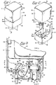
- a soap dispensing system constructed in accordance with and embodying the features of the present invention.
- the soap dispensing system 20 comprises a dispenser 25 adapted to be mounted on an associated support surface 21, such as on a wall 22 and a disposable cartridge 90 which contains a supply of liquid soap and is removably mountable on the dispenser 25 for cooperation therewith to control the dispensing of liquid soap therefrom.
- the dispenser 25 includes a housing 30, which is preferably of unitary one-piece construction and may be formed of molded plastic.
- the housing 30 includes a flat rectangular base wall 31 and upstanding rectangular mounting wall 32 integral with the base wall 31 at the rear edge thereof and disposed substantially perpendicular thereto.
- the mounting wall 32 may have fastener holes 33 therethrough for receiving associated fasteners (not shown), securely to mount the housing 30 on the associated support surface 21.
- Integral with the base wall 31 and extending upwardly therefrom along the front and side edges thereof is a continuous peripheral flange 34, the front portion of which has a notch 34a in the upper edge thereof.
- Side flanges 35 are respectively integral with the side edges of the mounting wall 32 and project forwardly therefrom to join the peripheral flange 34.
- retaining rails 36 are integral with the side flanges 35 at the forward or distal edges thereof, and projecting laterally inwardly therefrom substantially parallel to the mounting wall 32.
- retaining rails 36 Integral with the base wall 31 and with the mounting wall 32 and substantially perpendicular to each are a pair of laterally spaced-apart, upstanding support plates 37, respectively provided with laterally aligned bearing notches 38 in the upper edges thereof.
- Formed in the base wall 31 is an elongated generally rectangular opening 39 (Figs. 3 and 4) which extends laterally between the support plates 37, the opening 39 having a rearwardly extending rectangular arm 39a and having an arcuate forward end (not shown).
- a receptacle 40 Integral with the housing 30 is a receptacle 40 having a peripheral wall 41 which defines the forward portion of the opening 39, the peripheral wall 41 having an arcuate front end and parallel side portions, which side portions are respectively parallel to the support plates 37 and are integral with the inner surfaces thereof at the front ends thereof.
- the peripheral wall 41 projects above and below the base wall 31 and is closed at its lower end by a bottom wall 42 which is disposed substantially parallel to the base wall 31.
- the bottom wall 42 has a circular opening 43 therein adjacent to the forward end thereof, and a generally T-shaped slot 44 therethrough (Fig. 3) just rearwardly of the circular opening 43.
- Respectively formed in the side portions of the peripheral wall 41 below the base 31 are two laterally aligned circular pivot openings 45 (see Fig. 5).
- a stop web 48 laterally spans the side portions of the peripheral wall 41, extending a slight distance above and below the base wall 31, the web 48 having a rectangular notch 48a (Fig. 5) in the lower edge thereof.
- a rectangular stop web 49 is disposed substantially parallel to the stop web 48 and defines a chord across the arcuate front end of the peripheral wall 41, the upper edges of the stop webs 48 and 49 lying substantially in a common horizontal plane.
- the dispenser 25 also includes a discharge assembly 50 which is removably mounted in the housing 30.
- the discharge assembly 50 includes a handle 51 comprising a rectangular plate 52 provided at its upper end with an inclined portion 53, which is in turn provided at its distal end with laterally outwardly extending cylindrical pivot lugs 54.
- the handle 51 is adapted to be dropped into the housing 30 between the support plates 37 and through the opening 39 in the base wall 31, the pivot lugs 54 being respectively received in the bearing notches 38 for pivotally supporting the handle 51 for movement between actuating and retracted positions.
- the plate 52 has a width slightly less than the width of the opening 39, so that the base wall 31 at the rear end of the opening 39 and the rear flanges 46 of the receptacle 40 provide rear and front stops to limit the pivotal movement of the handle 51.
- Formed in the front surface of the plate 52 is a rectangular recess 55, in the lower end of which is formed a rectangular slot 56 which extends through the thickness of the plate 52 midway between the side edges thereof and in position so as to be disposed below the base wall 31 when the handle 51 is disposed in its mounted condition in the housing 30.
- the discharge assembly 50 also includes a bias unit 60 which comprises a latch member 61 and a bias leaf 70.
- the latch member 61 is generally in the form of a clevis having a pair of parallel, spaced-apart arms 62, respectively provided with angled feet 63, at the lower ends thereof (see Fig. 5).
- the feet 63 are respectively provided with laterally outwardly extending circularly cylindrical pivot lugs (not shown) each having a substantially square key socket (also not shown) formed in the outer end thereof, which may extend laterally completely therethrough, as was illustrated in U.S. Patent No. 4,673,109, the disclosure of which is herein incorporated by reference.
- Each of the feet 63 is also provided on its inner surface with a bearing boss 66.
- the arms 62 are interconnected at their upper ends by a bight portion 67 provided with a forwardly extending latch flange 68 having a part frustoconical cam surface 69 thereon.
- the latch member 61 is dimensioned to fit within the receptacle 40 with the arms 62 respectively disposed along the inner surfaces of the side portions of the peripheral wall 41.
- the arms 62 are resiliently deflected together to permit the pivot lugs to clear the inner surfaces of the peripheral wall 41, and then the latch member 61 is lowered into the receptacle 40 until the pivot lugs respectively snap out into the pivot opening 45, pivotally to mount the latch member 61.
- the length of the arms 62 is such that when the latch member 61 is in this mounted condition, the latch flange 68 is disposed a predetermined distance above the upper end of the receptacle 40.
- the bias leaf 70 comprises a thin, flat, rectangular band which is formed of a suitable flexible and resilient material, such as a suitable plastic.
- One end of the bias leaf 70 is fixedly secured to the rear surface of the bight portion 67 of the latch member 61 by suitable means (not shown).
- the bias leaf 70 is fabricated with a predetermined curvature therein, and is provided with a curved tip 72 at its distal end which has a rectangular slot 73 therethrough for a purpose to be explained more fully below.
- a key (not shown) having a lug thereon which is disposed for mating engagement in one of the key sockets to effect manual rotation of the latch member 61 about the axis of the pivot lugs, for a purpose which will be explained below.
- the discharge assembly 50 also includes a pump member 80, which is generally in the shape of a rectangular, box-like, open-top frame. More particularly, the pump member 80 includes a pair of parallel rectangular side walls 81 interconnected, respectively at the forward and rearward ends thereof by a front bearing wall 82 and a rear wall 83.
- the rear wall 83 has an extension portion 84 which projects upwardly above the upper edges of the side wall 81 and is provided with a forwardly extending pin 85. Integral with the outer or rear surface of the rear wall 83 is a rearwardly extending rectangular positioning lug 86.
- the side walls 81 are interconnected at the lower edges thereof, intermediate the front and rear ends thereof by a rectangular bottom web 87.
- the pump member 80 is dimensioned so that it can fit between the notches 47 of the receptacle rear flanges 46, through the notch 48a in the stop web 48 and between the bearing bosses 66 of latch member 61 for reciprocating siding movement forwardly and rearwardly along the bottom wall 42 of the receptacle 40 between pumping and release positions.
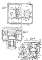
- a plate 88 is horizontally mounted within the flange 34 and has an aperture 89 therein of irregular shape. As before seen in Figs. 2 and 4, the aperture 89 has a circular edge portion 89a, straight edge portions 89b and 89c, and first and second lobe portions 89d and 89e.
- This plate 88 with the irregular aperture 89 serves as on part of an anti boot-leg device and is fixedly mounted inside the dispenser 25, at a predetermined height, as will be explained.
- the pump member 80 is mounted in the receptacle 40.
- the front end of the pump member 80 is inserted upwardly and forwardly into the receptacle 40 between the notches 47 in the rear flanges 46, the arm 39a of the opening 39 providing clearance for the extension portion 84 of the rear wall 83.
- the pump member 80 is slid forwardly through the notch 48a in the stop web 48 and between the bearing bosses 66 on the latch member feet 63.
- the bias leaf 70 is received down into the pump member 80 and the pin 85 is inserted through the slot 73 of the bias leaf 70 so that the bias leaf 70 bears against the rear wall 83 of the pump member 80.
- the handle 51 is mounted.
- the pump member 80 is slid forwardly against the urging of the bias leaf 70 to provide clearance so that the handle plate 52 can be dropped down through the opening 39 behind he receptacle rear flanges 46.
- the arms 62 of the latch member 61 bear against the rear surface of the stop web 48 to limit forward pivotal movement of the latch member of the latch member 61 when the pump member 80 is slid forwardly.
- the handle 51 is then dropped into position with the pivot lugs 54 disposed in the bearing notches 38, as explained above.
- the pump member 80 is then released and it slides rearwardly under the urging of the bias leaf 70 to a normal rest position, illustrated in Fig.
- the cartridge 90 includes a generally box-like container 91, which may be formed of a suitable plastic material.
- the container 91 is generally in the form of a rectangular parallelepiped having a top wall 92, a bottom wall 93, a front wall 94 having a cut away portion 94a and a lug portion 94b, a rear wall 95 and a pair of opposed side walls 96.
- the front wall 94 and the side walls 96 are set back or recessed along their lower edges adjacent to their junction with the bottom wall 93 to define a support shoulder 97.
- the top wall 92 has a portion 92a which projects rearwardly a slight distance beyond the rear wall 95 to form an overhang which defines a stop flange 98.
- the lower portion of the grooves 100 are cut away, as at 101, so as to define lugs 102 adjacent to the upper ends of the grooves 100.
- the top part of the cartridge 90 comprising the top wall 92 and the upper parts of the front, rear and side walls has a receptacle 103 extending therein (see Figs.
- a filter 105 which is a porous "teflon" or polytetrafluoro-ethylene plastics sold under the trade name "Porex", for a moulded porous PTFE, having a water entry point of 1.6 p.s.i. which is equivalent to 43 inches of water (approximately 11kPa).
- the filter has an average pore size of 25 microns and a pore volume of 42%.
- the melting range of the filter is 314-338°C and the crystallization range is 275-320°C.
- Porex is sold by Porex Technologies of Fiarburn, Georgia which publishes complete specifications for the material.
- a cylindrical nozzle or neck 105a Integral with the bottom wall 93 adjacent to the forward end thereof is a cylindrical nozzle or neck 105a which projects downwardly from the bottom wall 93 and surrounds an outlet opening 106 therein (Fig. 10).
- a frusto-conical portion 105b connects the flat bottom wall 93 with the cylindrical neck 105a.
- the neck 105a has a radially outwardly extending circumferential rib 107 forming an external thread and terminates in an annular end surface 108.
- Extending outwardly from the neck 105a is one or more irregular abutment surfaces or bosses 109 having a plurality of boss surfaces 109a-109e which are complimentary in shape to the irregular opening 89a-89e in plate 88.
- a compressible nipple 110 Secured to the neck 105a and depending therefrom is a compressible nipple 110 having an annular flange (not shown) at the upper end thereof which is integral with an upstanding cylindrical wall adapted to surround the lower end of the neck 105a and abut against the circumferential flange.
- the nipple 110 is provided with a normally-closed discharge slit 113 at its distal end.
- a check valve assembly Trapped between the flange and the end surface 108 of the neck 105a is a check valve assembly (not shown), the parts being clamped together by a cylindrical retainer clip 116 which securely holds the nipple 110 and the valve assembly on the neck 105a.
- the construction, assembly and operation of the neck 105a, the nipple 110 and the valve assembly are all described in US-A-4673109 and US-A-4886192.
- the cartridge 90 is inexpensive to manufacture so as to be disposable.
- the container 91 is filled with liquid soap by the manufacturer or supplier of the cartridge 90 and the nipple 110 is then mounted in place.
- the cartridge 90 and the filter 105 if of a specific size, permits the dispenser to be activated many times without establishing a vacuum that distorts the cartridge 90.
- mounting the cartridge 90 it is placed over the dispenser 25 with the neck 105a disposed downwardly.
- the cartridge 90 is slid down along the mounting wall 32, with the retaining rails being respectively received in the longitudinal grooves 100.
- the nipple 110 extends downwardly into the receptacle 40 between the stop webs 48 and 49 and in coaxial alignment with the circular opening 43 in the bottom wall 42.
- the latch flange 68 of the latch member 61 projects forwardly beyond the stop web 48 so as to obstruct the path of the neck 105a. More particularly, the lower end of the retainer clip 116 engages the cam surface 69 and cams the latch member 61 into pivotal movement rearwardly to accommodate passage of the retainer clip 116. As soon as the retainer clip 116 has moved past the latch flange 68, it snaps back forwardly under the urging of the bias leaf 70 into the space between the circumferential rib 107 and the circumferential flange 108 for engagement with the latter to prevent retrograde movement of the cartridge 90.
- the container 91 is dimensioned so that when the cartridge 90 is disposed in its use position on the dispenser 25, the upper edge of the peripheral flange 34 of the housing 30 is disposed for engagement with the support shoulder 97 of the container 91 and the upper edge of the mounting wall 32 is disposed for engagement with the stop flange 98.
- the stop flange 98 wraps around the sides of the container 91 for engagement with the upper ends of the side flanges 35 of the housing 30.
- the parts are all dimensioned so that when the cartridge 90 is disposed in its use position on the dispenser 25, the outer surfaces of the front wall 94 and the side walls 96 are, respectively, substantially coplanar with the corresponding portions of the outer surface of the housing peripheral flange 34, and the outer surface of the side walls 96, are respectively substantially coplanar with the outer surfaces of the housing side flanges 35 so as to present an attractive, smooth outward appearance. Additionally, the front lug 94b fits within and rests upon the notch 34a in the front wall 34. It will be appreciated that when the cartridge 90 is disposed in its use position, the lugs 102 engage the upper ends of the retaining rails 36, effectively to prevent forward tilting movement of the cartridge 90 with respect to the dispenser 25.
- the venting of the container 91 through the receptacle 103 and filter 105 prevents too large a vacuum from being established in the container and permits, for the first time, dispensing many consecutive doses of soap of substantially the same volume without distorting the sides 96 of the container 91. It has been determined that for a one litre volume container the filter 105 of "Porex" (25 micron material) should be 1/4 inch (6.35 mm.) in diameter and not longer than about 5/16 inch (7.94 mm.). The filter 105 is slightly larger than the receptacle 103 so a good friction fit occurs to prevent the filter 105 from falling out of the receptacle.
- the resistance of the filter 105 should be enough to establish about 4-5 inches (6.35-7.94 mm.) vacuum when the soap level is above the filter 105 (to prevent soap leaking from the nipple 110) but at no time should the filter 105 prevent sufficient replacement of air after a dispensing operation so that the vacuum exceeds about 12 inches of water (about 3kPa), at which level the side walls 96 distort.
- Use of the Porex® material is important because even after the level of soap has dropped below the receptacle 103 and filter 105 container therein, there is still a slight negative pressure in the container 91, which limits or entirely prevents soap dripping from the distal end of the nipple 110 at the slit 113. This is very important commercially since one of the biggest complaints about soap dispensers is the mess which some create.
- the check valve assembly (not shown) normally permits liquid soap to flow downwardly through the neck 105a to fill the nipple 110 with a charge of liquid soap.
- a user places his palm under the nipple 110 and pulls the handle 51 forwardly to its actuating position with his fingers. This drives the pump member 80 forwardly to its pumping position and into engagement with the nipple 110, compressing it and ejecting the charge of liquid soap therefrom through the discharge slit 113, this compression also serving to close the check valve assembly to prevent liquid soap from flowing back up from the nipple 110 into the neck 105a.
- the pump member 80 When the handle 51 is released, the pump member 80 returns to its release position and the handle 51 is returned to its retracted position under the urging of the bias leaf 70.
- the check valve assembly reopens to permit a new charge of liquid soap to flow into the nipple 110.
- the cartridge 90 When the cartridge 90 is spent, it is removed by the serviceman, as described in US-A-4673109.
- the anti-bootleg feature of this invention represents an advance in the art and requires cooperation between the plate 88 and irregular opening 89 therein and the irregular abutment surfaces or bosses 109 on the cartridge container 91.
- complimentary plate openings are not illustrated for the alternative configuration of Figs. 11a-11c, it should be readily apparent that various configurations are available to permit one distributor to have a "proprietary" dispenser/cartridge combination. Again, commercially this is of paramount importance because "bootleg" refillers abound and distributors are continually trying to protect their customers.
- bosses 109 around the circumference of the neck 105a various different "proprietary" dispenser/cartridge combinations can be made.
- the plate 88 would have to be altered. It a cartridge 90 without the appropriate bearing surfaces is used, the cartridge 90 will not fit into the plate 88 far enough for the pump member 80 to contact the entire portion of nipple 110 and the system will not operate correctly resulting in little soap being dispensed.
- an improved soap dispensing system which is simple and economical in construction, utilizing a dispenser which carries a discharge assembly and a disposable liquid soap cartridge removably mountable on the dispenser, wherein the cartridge is automatically latched in position on the dispenser to prevent unauthorized removal thereof, and the parts of the discharge assembly are few can be readily assembled and disassembled without the use of tools, and retain themselves in the assembled mounted condition without any fastening means.
- the dispensing-system enables repeated operation of the dispenser without establishing a vacuum in the soap cartridge which distorts the cartridge and includes an anti-bootleg device permitting several proprietary combinations to be used.
Landscapes
- Health & Medical Sciences (AREA)
- Public Health (AREA)
- Containers And Packaging Bodies Having A Special Means To Remove Contents (AREA)
Applications Claiming Priority (2)
| Application Number | Priority Date | Filing Date | Title |
|---|---|---|---|
| US696070 | 1991-05-06 | ||
| US07/696,070 US5174476A (en) | 1991-05-06 | 1991-05-06 | Liquid soap dispensing system |
Publications (1)
| Publication Number | Publication Date |
|---|---|
| EP0514068A1 true EP0514068A1 (de) | 1992-11-19 |
Family
ID=24795595
Family Applications (1)
| Application Number | Title | Priority Date | Filing Date |
|---|---|---|---|
| EP92304044A Withdrawn EP0514068A1 (de) | 1991-05-06 | 1992-05-05 | Flüssigseifenspender |
Country Status (4)
| Country | Link |
|---|---|
| US (1) | US5174476A (de) |
| EP (1) | EP0514068A1 (de) |
| JP (1) | JPH05130948A (de) |
| CA (1) | CA2067402A1 (de) |
Cited By (1)
| Publication number | Priority date | Publication date | Assignee | Title |
|---|---|---|---|---|
| EP2111780A1 (de) * | 2008-04-22 | 2009-10-28 | Fritz Ostermann Handelsgesellschaft mbH | Seifenspender zum Befestigen an einer Wand |
Families Citing this family (70)
| Publication number | Priority date | Publication date | Assignee | Title |
|---|---|---|---|---|
| US5437394A (en) * | 1992-09-23 | 1995-08-01 | Ruck; Wolf E. | Viscous liquid dispenser |
| US5265772A (en) * | 1992-10-19 | 1993-11-30 | Gojo Industries, Inc. | Dispensing apparatus with tube locator |
| US5379813A (en) * | 1993-09-10 | 1995-01-10 | Ing; Hwang L. C. | Liquid dispenser |
| USD354414S (en) | 1993-10-20 | 1995-01-17 | Impact Products, Inc. | Container for liquids |
| US5439144A (en) * | 1993-12-27 | 1995-08-08 | Steiner Company, Inc. | Liquid soap dispensing system |
| US5445288A (en) * | 1994-04-05 | 1995-08-29 | Sprintvest Corporation Nv | Liquid dispenser for dispensing foam |
| US5810204A (en) * | 1996-10-15 | 1998-09-22 | James River Corporation | Apparatus for dispensing liquid soap or other liquids |
| EP0842630A1 (de) * | 1996-11-19 | 1998-05-20 | Unilever N.V. | Dosierspender für Flüssigseife oder dergleichen |
| FR2772007B1 (fr) * | 1997-12-08 | 2000-02-04 | Sivel | Dispositif de conditionnement et distribution d'un produit, avec pompe manuelle et recipient a filtre d'entree d'air dans le recipient |
| US6082586A (en) * | 1998-03-30 | 2000-07-04 | Deb Ip Limited | Liquid dispenser for dispensing foam |
| US6006388A (en) * | 1998-04-14 | 1999-12-28 | Young; Cecil Blake | Dispenser for dispensing concentrated liquid soap to industrial cleaning apparatuses |
| US6247621B1 (en) | 1998-09-30 | 2001-06-19 | Kimberly-Clark Worldwide, Inc. | Dual use dispensing system |
| US6073812A (en) * | 1999-01-25 | 2000-06-13 | Steris Inc. | Filtered venting system for liquid containers which are susceptible to contamination from external bioburden |
| US6068162A (en) * | 1999-02-18 | 2000-05-30 | Avmor Ltd. | Adjustable soap dispenser |
| USD454017S1 (en) | 1999-10-08 | 2002-03-05 | Gent-I-Kleen Products, Inc. | Top with ledge for 5 liter dispenser |
| USD443781S1 (en) | 1999-10-08 | 2001-06-19 | Gent-I-Kleen Products, Inc. | Bottom plate for 5 liter dispenser |
| USD444978S1 (en) | 1999-10-08 | 2001-07-17 | Gent-I-Kleen Products, Inc. | Reservoir for 5 liter dispenser |
| USD436282S1 (en) | 1999-10-08 | 2001-01-16 | Gent-L-Kleen Products, Inc. | 5 liter dispenser with preformed notch |
| USD443782S1 (en) | 1999-10-08 | 2001-06-19 | Gent-I-Kleen Products, Inc. | 5 liter dispenser |
| USD443452S1 (en) | 1999-10-08 | 2001-06-12 | Gent-I-Kleen Products, Inc. | Back plate for 5 liter dispenser |
| US6321943B1 (en) | 1999-10-09 | 2001-11-27 | Gent-I-Kleen Products, Inc. | Soap dispenser for soap of different viscosity |
| USD443780S1 (en) | 1999-10-09 | 2001-06-19 | Gent-L-Kleen | 5 liter dispenser bottle with preformed notch |
| USD441998S1 (en) | 1999-10-09 | 2001-05-15 | Gent-L-Kleen | 5 liter dispenser bottle |
| JP3790084B2 (ja) * | 2000-02-22 | 2006-06-28 | 理想科学工業株式会社 | インクボトル装着装置 |
| US6543651B2 (en) | 2000-12-19 | 2003-04-08 | Kimberly-Clark Worldwide, Inc. | Self-contained viscous liquid dispenser |
| US6516976B2 (en) | 2000-12-19 | 2003-02-11 | Kimberly-Clark Worldwide, Inc. | Dosing pump for liquid dispensers |
| US6540117B2 (en) | 2001-03-30 | 2003-04-01 | Kimberly-Clark Worldwide, Inc. | Dosing pump for liquid dispensers |
| DE10125842B4 (de) * | 2001-05-25 | 2005-06-09 | Höhensteiger, Alois | Spender für flüssige Medien wie Flüssigseife, Desinfektionsmittel etc. |
| DE10147702A1 (de) * | 2001-09-27 | 2003-04-10 | Form Orange Produktentwicklung | Befeuchtungsvorrichtung für Toilettenpapier |
| USD475232S1 (en) | 2002-01-25 | 2003-06-03 | Nice-Pak Products, Inc. | Wall-mounted canister |
| USD470911S1 (en) | 2002-05-02 | 2003-02-25 | Isaac Docsol | Rinse station |
| US7066356B2 (en) * | 2002-08-15 | 2006-06-27 | Ecolab Inc. | Foam soap dispenser for push operation |
| FR2873358B1 (fr) * | 2004-07-20 | 2006-11-10 | Sivel Soc Civ Ile | Dispositif de conditionnement et distribution d'un produit avec flacon filtre sterile muni d'un embout |
| CA2791887C (en) * | 2005-04-22 | 2014-10-07 | Gotohti.Com Inc. | Foam pump with bellows spring |
| CA2504989C (en) * | 2005-04-22 | 2013-03-12 | Gotohti.Com Inc. | Stepped pump foam dispenser |
| US7770874B2 (en) * | 2005-04-22 | 2010-08-10 | Gotohii.com Inc. | Foam pump with spring |
| CA2578422A1 (en) * | 2006-05-02 | 2007-11-02 | Gotohti.Com Inc. | Wall plate system with releasable lock |
| CA2545654A1 (en) * | 2006-05-02 | 2007-11-02 | Gotohti.Com Inc. | Wall plate system for dispensers |
| CA117313S (en) | 2006-08-31 | 2007-10-30 | Gotohti Com Inc | Wall plate |
| US20080169264A1 (en) * | 2007-01-12 | 2008-07-17 | Timothy James Kennedy | Bottle Capping Systems |
| US7740154B2 (en) * | 2007-01-12 | 2010-06-22 | The Clorox Company | Bottle Fitment |
| USD611376S1 (en) | 2009-03-12 | 2010-03-09 | Bemis Manufacturing Company | Portion of a metering device |
| JP5654257B2 (ja) * | 2010-04-07 | 2015-01-14 | 株式会社ニイタカ | 液体供給装置及び液体供給方法 |
| US8814005B2 (en) | 2012-04-27 | 2014-08-26 | Pibed Limited | Foam dispenser |
| US9204765B2 (en) * | 2012-08-23 | 2015-12-08 | Gojo Industries, Inc. | Off-axis inverted foam dispensers and refill units |
| US20140054320A1 (en) * | 2012-08-23 | 2014-02-27 | Gojo Industries, Inc. | Off-axis inverted dispensers and refill units |
| US20140054323A1 (en) | 2012-08-23 | 2014-02-27 | Gojo Industries, Inc. | Horizontal pumps, refill units and foam dispensers with integral air compressors |
| US9307871B2 (en) | 2012-08-30 | 2016-04-12 | Gojo Industries, Inc. | Horizontal pumps, refill units and foam dispensers |
| US9179808B2 (en) | 2012-08-30 | 2015-11-10 | Gojo Industries, Inc. | Horizontal pumps, refill units and foam dispensers |
| USD731203S1 (en) * | 2013-11-20 | 2015-06-09 | Nse Products, Inc. | Fluid cartridge |
| USD731204S1 (en) * | 2013-11-20 | 2015-06-09 | Nse Products, Inc. | Fluid cartridge |
| USD730077S1 (en) | 2013-11-20 | 2015-05-26 | Nse Products, Inc. | Fluid dispenser |
| USD733455S1 (en) * | 2013-11-20 | 2015-07-07 | Nse Products, Inc. | Fluid cartridge assembly |
| US10123661B2 (en) * | 2013-11-27 | 2018-11-13 | Archer Manufacturing, Inc. | Tamper-proof and ligation resistant dispenser for liquids |
| US10743720B2 (en) | 2013-11-27 | 2020-08-18 | Archer Manufacturing, Inc. | Tamper-resistant devices and systems for wall-mounted dispensers |
| US10743721B2 (en) | 2013-11-27 | 2020-08-18 | Archer Manufacturing, Inc. | Tamper-resistant devices and systems for wall-mounted dispensers |
| USD717666S1 (en) | 2014-03-14 | 2014-11-18 | The Clorox Company | Fluid dispenser |
| RU2674873C2 (ru) | 2014-05-12 | 2018-12-13 | Деб АйПи Лимитед | Улучшенный пенный насос |
| US9737177B2 (en) | 2014-05-20 | 2017-08-22 | Gojo Industries, Inc. | Two-part fluid delivery systems |
| US10022741B2 (en) | 2014-08-22 | 2018-07-17 | Nse Products, Inc. | Selectively actuated fluid dispenser |
| DK3324805T3 (da) | 2015-07-23 | 2020-11-02 | William J Schalitz | Engangssæbedispenser |
| CN109906048A (zh) * | 2016-11-15 | 2019-06-18 | 荷兰联合利华有限公司 | 用于流体的涂抹器装置 |
| USD1002387S1 (en) | 2019-10-03 | 2023-10-24 | Marietta Corporation | Bottle and a mount assembly |
| USD995309S1 (en) | 2021-03-23 | 2023-08-15 | Marietta Corporation | Bottle mount assembly with insert tool |
| USD988878S1 (en) | 2021-07-06 | 2023-06-13 | Marietta Corporation | Bottle and mount assembly |
| USD996856S1 (en) * | 2022-02-23 | 2023-08-29 | Hansgrohe Se | Liquid soap dispenser |
| US12103032B2 (en) | 2022-06-29 | 2024-10-01 | Dario Donati | Liquid product distribution assembly |
| USD1021459S1 (en) * | 2022-10-03 | 2024-04-09 | Cintas Corporate Services, Inc. | Refill container |
| JP1770339S (ja) * | 2024-01-24 | 2024-05-14 | ソープディスペンサー | |
| USD1077514S1 (en) * | 2024-05-28 | 2025-06-03 | Jiangmen Junshun Industrial Co., Ltd. | Soap dispenser |
Citations (7)
| Publication number | Priority date | Publication date | Assignee | Title |
|---|---|---|---|---|
| GB1105497A (en) * | 1964-06-22 | 1968-03-06 | Zyma Sa | Liquid dispensing apparatus |
| GB2106877A (en) * | 1981-08-17 | 1983-04-20 | Eugene Meierhoefer | Sterile solution delivery and venting device |
| US4391308A (en) * | 1981-04-16 | 1983-07-05 | Steiner Corporation | Soap dispensing system |
| US4429812A (en) * | 1981-04-16 | 1984-02-07 | Steiner Corporation | Soap dispensing system |
| US4673109A (en) * | 1985-10-18 | 1987-06-16 | Steiner Company, Inc. | Liquid soap dispensing system |
| EP0280611A1 (de) * | 1987-02-17 | 1988-08-31 | L'air Liquide, Societe Anonyme Pour L'etude Et L'exploitation Des Procedes Georges Claude | Filter für eine (Luft)-Abzugsvorrichtung und Vorrichtung mit einem solchen Filter |
| US4930667A (en) * | 1989-01-23 | 1990-06-05 | Steiner Company, Inc. | Breathing device for soap dispenser |
Family Cites Families (10)
| Publication number | Priority date | Publication date | Assignee | Title |
|---|---|---|---|---|
| US1234089A (en) * | 1916-06-06 | 1917-07-17 | Dominic J Reinhardt | Oil-can. |
| GB701809A (en) * | 1951-04-25 | 1954-01-06 | Churchill Henry Winston S | Improvements relating to apparatus for dispensing pastes, liquids and other substances |
| US2812117A (en) * | 1955-03-29 | 1957-11-05 | Abbott Lab | Venoclysis apparatus |
| US4660733A (en) * | 1981-06-08 | 1987-04-28 | Snyder Industries, Inc. | Cone bottom tank and liftable tank support |
| IT1208551B (it) * | 1985-05-20 | 1989-07-10 | Steiner Co Int Sa | Erogatore perfezionato di sapone liquido e relativa cartuccia di alimentazione. |
| US4646945A (en) * | 1985-06-28 | 1987-03-03 | Steiner Company, Inc. | Vented discharge assembly for liquid soap dispenser |
| US4699296A (en) * | 1986-02-04 | 1987-10-13 | Schrock Jr John | Dispensing device for external or intravenous injection of fluids into a patient |
| US4792059A (en) * | 1987-02-04 | 1988-12-20 | United States Thermoelectric Corporation | Sealed hot, cold and room temperature pure water dispenser |
| US4834267A (en) * | 1987-11-02 | 1989-05-30 | Elkay Manufacturing Company | Bottled water cooler air filter |
| US4964544A (en) * | 1988-08-16 | 1990-10-23 | Bobrick Washroom Equipment, Inc. | Push up dispenser with capsule valve |
-
1991
- 1991-05-06 US US07/696,070 patent/US5174476A/en not_active Expired - Fee Related
-
1992
- 1992-04-27 JP JP4107840A patent/JPH05130948A/ja active Pending
- 1992-04-28 CA CA002067402A patent/CA2067402A1/en not_active Abandoned
- 1992-05-05 EP EP92304044A patent/EP0514068A1/de not_active Withdrawn
Patent Citations (7)
| Publication number | Priority date | Publication date | Assignee | Title |
|---|---|---|---|---|
| GB1105497A (en) * | 1964-06-22 | 1968-03-06 | Zyma Sa | Liquid dispensing apparatus |
| US4391308A (en) * | 1981-04-16 | 1983-07-05 | Steiner Corporation | Soap dispensing system |
| US4429812A (en) * | 1981-04-16 | 1984-02-07 | Steiner Corporation | Soap dispensing system |
| GB2106877A (en) * | 1981-08-17 | 1983-04-20 | Eugene Meierhoefer | Sterile solution delivery and venting device |
| US4673109A (en) * | 1985-10-18 | 1987-06-16 | Steiner Company, Inc. | Liquid soap dispensing system |
| EP0280611A1 (de) * | 1987-02-17 | 1988-08-31 | L'air Liquide, Societe Anonyme Pour L'etude Et L'exploitation Des Procedes Georges Claude | Filter für eine (Luft)-Abzugsvorrichtung und Vorrichtung mit einem solchen Filter |
| US4930667A (en) * | 1989-01-23 | 1990-06-05 | Steiner Company, Inc. | Breathing device for soap dispenser |
Cited By (2)
| Publication number | Priority date | Publication date | Assignee | Title |
|---|---|---|---|---|
| EP2111780A1 (de) * | 2008-04-22 | 2009-10-28 | Fritz Ostermann Handelsgesellschaft mbH | Seifenspender zum Befestigen an einer Wand |
| DE102008020103B4 (de) * | 2008-04-22 | 2016-02-04 | Fritz Ostermann Gmbh | Seifenspender zum Befestigen an einer Wand |
Also Published As
| Publication number | Publication date |
|---|---|
| JPH05130948A (ja) | 1993-05-28 |
| US5174476A (en) | 1992-12-29 |
| CA2067402A1 (en) | 1992-11-07 |
Similar Documents
| Publication | Publication Date | Title |
|---|---|---|
| US5209377A (en) | Disposable refill cartridge for a liquid soap dispensing system | |
| US5174476A (en) | Liquid soap dispensing system | |
| US5439144A (en) | Liquid soap dispensing system | |
| US4673109A (en) | Liquid soap dispensing system | |
| US5082150A (en) | Liquid dispensing system including a discharge assembly providing a positive air flow condition | |
| US4146156A (en) | Soap dispensing system | |
| AU768226B2 (en) | Compact fluid pump | |
| US4345627A (en) | Soap dispensing system | |
| US5826755A (en) | Liquid dispenser with selectably attachable actuator | |
| US4429812A (en) | Soap dispensing system | |
| EP2225988B1 (de) | Spendergehäuse | |
| AU778493B2 (en) | Wall-mounted dispenser for liquids | |
| JP3469995B2 (ja) | 液状品用ディスペンサー | |
| US7198177B2 (en) | Dispenser for dispensing a fluid, housing for such a dispenser, storage holder configured for placement therein and arrangement for the dosed pumping of a fluid from a fluid reservoir | |
| US4792064A (en) | Liquid soap dispenser | |
| CA2645953A1 (en) | Engagement flange for fluid dispenser pump piston | |
| US9737903B2 (en) | Soap dispenser | |
| US9968227B2 (en) | Liquid dispensing system | |
| CN115666343B (zh) | 用于流体分配系统的适配器组件 | |
| JPS6035148B2 (ja) | 液体せつけんの注入用カ−トリツジおよび分与装置 | |
| EP1525836B1 (de) | Doppelspender für hygienische Substanzen | |
| CA1248922A (en) | Fluid-dispensing apparatus | |
| JPH0230682B2 (ja) | Ekijosetsukennokodashisochi | |
| JPH07322969A (ja) | 液体石鹸吐出装置 |
Legal Events
| Date | Code | Title | Description |
|---|---|---|---|
| PUAI | Public reference made under article 153(3) epc to a published international application that has entered the european phase |
Free format text: ORIGINAL CODE: 0009012 |
|
| AK | Designated contracting states |
Kind code of ref document: A1 Designated state(s): AT BE CH DE DK ES FR GB IT LI LU NL PT SE |
|
| 17P | Request for examination filed |
Effective date: 19930215 |
|
| 17Q | First examination report despatched |
Effective date: 19940331 |
|
| STAA | Information on the status of an ep patent application or granted ep patent |
Free format text: STATUS: THE APPLICATION IS DEEMED TO BE WITHDRAWN |
|
| 18D | Application deemed to be withdrawn |
Effective date: 19951118 |