EP0514580A1 - Convertisseur - Google Patents
Convertisseur Download PDFInfo
- Publication number
- EP0514580A1 EP0514580A1 EP91108466A EP91108466A EP0514580A1 EP 0514580 A1 EP0514580 A1 EP 0514580A1 EP 91108466 A EP91108466 A EP 91108466A EP 91108466 A EP91108466 A EP 91108466A EP 0514580 A1 EP0514580 A1 EP 0514580A1
- Authority
- EP
- European Patent Office
- Prior art keywords
- converter
- arrangement according
- converter arrangement
- switch
- rectifier bridge
- Prior art date
- Legal status (The legal status is an assumption and is not a legal conclusion. Google has not performed a legal analysis and makes no representation as to the accuracy of the status listed.)
- Granted
Links
- 238000004804 winding Methods 0.000 claims description 17
- 239000003990 capacitor Substances 0.000 claims description 7
- 239000004065 semiconductor Substances 0.000 claims description 6
- 230000007547 defect Effects 0.000 abstract 2
- 230000001133 acceleration Effects 0.000 abstract 1
- 230000002950 deficient Effects 0.000 abstract 1
- 230000003137 locomotive effect Effects 0.000 description 6
- 238000010586 diagram Methods 0.000 description 3
- 230000004913 activation Effects 0.000 description 1
- 238000005275 alloying Methods 0.000 description 1
- 230000007257 malfunction Effects 0.000 description 1
- 230000000717 retained effect Effects 0.000 description 1
Images

Classifications
-
- B—PERFORMING OPERATIONS; TRANSPORTING
- B60—VEHICLES IN GENERAL
- B60L—PROPULSION OF ELECTRICALLY-PROPELLED VEHICLES; SUPPLYING ELECTRIC POWER FOR AUXILIARY EQUIPMENT OF ELECTRICALLY-PROPELLED VEHICLES; ELECTRODYNAMIC BRAKE SYSTEMS FOR VEHICLES IN GENERAL; MAGNETIC SUSPENSION OR LEVITATION FOR VEHICLES; MONITORING OPERATING VARIABLES OF ELECTRICALLY-PROPELLED VEHICLES; ELECTRIC SAFETY DEVICES FOR ELECTRICALLY-PROPELLED VEHICLES
- B60L3/00—Electric devices on electrically-propelled vehicles for safety purposes; Monitoring operating variables, e.g. speed, deceleration or energy consumption
- B60L3/0023—Detecting, eliminating, remedying or compensating for drive train abnormalities, e.g. failures within the drive train
-
- B—PERFORMING OPERATIONS; TRANSPORTING
- B60—VEHICLES IN GENERAL
- B60L—PROPULSION OF ELECTRICALLY-PROPELLED VEHICLES; SUPPLYING ELECTRIC POWER FOR AUXILIARY EQUIPMENT OF ELECTRICALLY-PROPELLED VEHICLES; ELECTRODYNAMIC BRAKE SYSTEMS FOR VEHICLES IN GENERAL; MAGNETIC SUSPENSION OR LEVITATION FOR VEHICLES; MONITORING OPERATING VARIABLES OF ELECTRICALLY-PROPELLED VEHICLES; ELECTRIC SAFETY DEVICES FOR ELECTRICALLY-PROPELLED VEHICLES
- B60L9/00—Electric propulsion with power supply external to the vehicle
- B60L9/16—Electric propulsion with power supply external to the vehicle using AC induction motors
- B60L9/30—Electric propulsion with power supply external to the vehicle using AC induction motors fed from different kinds of power-supply lines
-
- H—ELECTRICITY
- H02—GENERATION; CONVERSION OR DISTRIBUTION OF ELECTRIC POWER
- H02M—APPARATUS FOR CONVERSION BETWEEN AC AND AC, BETWEEN AC AND DC, OR BETWEEN DC AND DC, AND FOR USE WITH MAINS OR SIMILAR POWER SUPPLY SYSTEMS; CONVERSION OF DC OR AC INPUT POWER INTO SURGE OUTPUT POWER; CONTROL OR REGULATION THEREOF
- H02M5/00—Conversion of AC power input into AC power output, e.g. for change of voltage, for change of frequency, for change of number of phases
- H02M5/40—Conversion of AC power input into AC power output, e.g. for change of voltage, for change of frequency, for change of number of phases with intermediate conversion into DC
- H02M5/42—Conversion of AC power input into AC power output, e.g. for change of voltage, for change of frequency, for change of number of phases with intermediate conversion into DC by static converters
- H02M5/44—Conversion of AC power input into AC power output, e.g. for change of voltage, for change of frequency, for change of number of phases with intermediate conversion into DC by static converters using discharge tubes or semiconductor devices to convert the intermediate DC into AC
- H02M5/443—Conversion of AC power input into AC power output, e.g. for change of voltage, for change of frequency, for change of number of phases with intermediate conversion into DC by static converters using discharge tubes or semiconductor devices to convert the intermediate DC into AC using devices of a thyratron or thyristor type requiring extinguishing means
- H02M5/45—Conversion of AC power input into AC power output, e.g. for change of voltage, for change of frequency, for change of number of phases with intermediate conversion into DC by static converters using discharge tubes or semiconductor devices to convert the intermediate DC into AC using devices of a thyratron or thyristor type requiring extinguishing means using semiconductor devices only
-
- B—PERFORMING OPERATIONS; TRANSPORTING
- B60—VEHICLES IN GENERAL
- B60L—PROPULSION OF ELECTRICALLY-PROPELLED VEHICLES; SUPPLYING ELECTRIC POWER FOR AUXILIARY EQUIPMENT OF ELECTRICALLY-PROPELLED VEHICLES; ELECTRODYNAMIC BRAKE SYSTEMS FOR VEHICLES IN GENERAL; MAGNETIC SUSPENSION OR LEVITATION FOR VEHICLES; MONITORING OPERATING VARIABLES OF ELECTRICALLY-PROPELLED VEHICLES; ELECTRIC SAFETY DEVICES FOR ELECTRICALLY-PROPELLED VEHICLES
- B60L2200/00—Type of vehicles
- B60L2200/26—Rail vehicles
-
- Y—GENERAL TAGGING OF NEW TECHNOLOGICAL DEVELOPMENTS; GENERAL TAGGING OF CROSS-SECTIONAL TECHNOLOGIES SPANNING OVER SEVERAL SECTIONS OF THE IPC; TECHNICAL SUBJECTS COVERED BY FORMER USPC CROSS-REFERENCE ART COLLECTIONS [XRACs] AND DIGESTS
- Y02—TECHNOLOGIES OR APPLICATIONS FOR MITIGATION OR ADAPTATION AGAINST CLIMATE CHANGE
- Y02T—CLIMATE CHANGE MITIGATION TECHNOLOGIES RELATED TO TRANSPORTATION
- Y02T10/00—Road transport of goods or passengers
- Y02T10/60—Other road transportation technologies with climate change mitigation effect
- Y02T10/64—Electric machine technologies in electromobility
Definitions
- the invention relates to a converter arrangement.
- Such converter arrangements are e.g. used in electric traction vehicles to power the traction motors.
- each motor is assigned a converter, which consists of an input converter or a four-quadrant actuator (possibility of feeding back into the power grid), an intermediate circuit and a motor-side converter (inverter).
- the converter arrangement is fed by a transformer which is connected to a single-phase voltage on the primary side.
- the converter arrangement is located directly on the contact wire.
- One converter unit with a common DC link is provided for each bogie and feeds two traction motors via inverters.
- the object of the present invention is to provide a converter arrangement in which as much starting torque as possible is retained in the event of a fault.
- the intermediate circuits are separated in the event of a fault (e.g. short circuit) in one of the converters, so that the converter and thus the motor-side converter (inverter) with the associated traction motor continue to operate.
- a fault e.g. short circuit
- inverter motor-side converter
- the converter arrangement according to the invention is advantageously suitable for both direct current and alternating current feed.
- the support capacitors in the DC link can be dimensioned smaller, so that there is a particularly space-saving embodiment.
- the converter arrangement can be designed according to claim 7; the controllable semiconductor elements are advantageously designed as GTO thyristors.
- Transistors in particular IGBTs (Insulated Gate Bipolar Transistors), can also be used for certain applications. With IGBTs in particular, only a small amount of effort is then required for activation.
- both the four-quadrant actuators and the pulse-controlled inverters can be easily formed from such converter modules. If the converter arrangement is connected to a single-phase voltage, two converter modules are required for each four-quadrant actuator. When using converter modules in the inverter, their number corresponds to the number of phases of the motor.
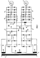
- FIG. 1 denotes an input part, which in the exemplary embodiments according to FIGS. 2 and 3 is designed as a transformer.
- the input part 1 is followed by a dash-dotted, framed converter arrangement.
- the converter arrangement consists of a number of converters corresponding to the number of drive motors (framed in dashed lines in FIG. 1).
- the exemplary embodiments shown in FIGS. 1 to 3 each include two converters 2, 3 and two drive motors 4, 5.
- Each converter 2 or 3 consists of at least one input converter 6 or 7 connected to the input part 1, an intermediate circuit ZK1 or ZK2 and a motor-side converter 12 or 13.
- the two converters 2 and 3 can be connected via at least one switch K4.
- the intermediate circuits ZK1, ZK2 are separated from one another, so that the undisturbed converter (e.g. converter 3) and thus the motor-side converter (e.g. converter 13) with the associated drive motor (eg drive motor 5) remains in operation.
- the input converters can e.g. be designed as a rectifier bridges (FIG 2) or as a four-quadrant actuator (FIG 3).
- the motor-side converters are designed as pulse inverters in FIGS. 2 and 3.
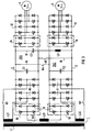
- the converter arrangement is fed with alternating current.
- the transformer 1 has a primary winding connected to a single-phase voltage and first, second and third secondary windings L21, L22, L23.
- the secondary windings L21, L22, L23 are connected via two converters 2, 3 to a multiphase drive motor 4 or 5, respectively.
- a number of rectifier bridges 6, 7, 8 (FIG. 2) or four-quadrant actuators 9, 10, 11 (FIG. 3) corresponding to the number of secondary windings L21, L22, L23 are arranged in the inverters 2, 3.
- Each four-quadrant actuator 9, 10, 11 comprises two converter modules, each of which consists of two GTO thyristors and two diodes connected antiparallel to these.
- the converter modules 91, 92 are provided with reference numerals and dash-dotted lines only for the four-quadrant actuator 9 bounded.
- the rectifier bridges 6, 7, 8 or four-quadrant actuators 9, 10, 11 can each be connected to the secondary windings L21, L22, L23 via a switch K1, K2, K3.
- the first secondary winding L21 is connected to the rectifier bridge 6 of the converter 2 and the second secondary winding L22 is connected to the rectifier bridge 7 of the converter 3.
- the third secondary winding L23 can be connected via a third switch K3 to the third rectifier bridge 8, which is parallel to the rectifier bridge 6 of the converter 2 as well as to the rectifier bridge 7 of the converter 3.
- the four-quadrant actuators 9, 10, 11 in FIG. 3 are also connected.
- the converter modules of the four-quadrant actuator 10, which are not provided with reference symbols, are arranged in the converter 2 and the converter modules of the four-quadrant actuator 11, which are likewise not provided with reference symbols, are arranged in the converter 3.
- the converter module 91 of the four-quadrant actuator 9 is assigned to the converter 2 and the converter module 92 of the four-quadrant actuator 9 is assigned to the converter 3.
- a pulse inverter 12 or 13 connected to the drive motor 4 or 5 is also arranged in each converter 2, 3.
- the pulse inverters 12 and 13 respectively consist of a number of converter modules 14 corresponding to the number of phases of the drive motor 4 and 5, respectively.
- the structure of the converter modules 14 corresponds to the structure of the converter modules 91 and 92.
- the rectifier bridges 6, 7, 8 or four-quadrant actuators 9, 10, 11 are coupled to the pulse-controlled inverters 12 and 13 via intermediate circuits ZK1 and ZK2.
- the intermediate circuits ZK1 and ZK2 each have a backup capacitor C1 or C2, which is connected in parallel to the rectifier bridges 6, 7, 8 (FIG. 2) or to the four-quadrant actuators 9, 10, 11 and the pulse inverters 12, 13 is arranged.
- the plus poles of the intermediate circuits ZK1 and ZK2 are connected via a connecting line 15, which can be disconnected via a switch K4. Accordingly, the negative poles of the intermediate circuits ZK1 and ZK2 are connected to one another via a connecting line 16, which can be separated by a switch K5.
- a suction circuit 17 is provided in parallel with the support capacitors C1 and C2, which e.g. is arranged between the positive pole of the intermediate circuit ZK1 and the negative pole of the intermediate circuit ZK2 and which comprises a capacitor C3 and an inductor L3 connected in series therewith.
- the suction circuit 17 is also connected in parallel with the support capacitor C2 of the intermediate circuit ZK2 via the switch K4.
- the intermediate circuit ZK1 is then single-pole at the potential of the upper line of the intermediate circuit ZK2 and the rectifier bridges 6,7 (FIG. 2) or the four-quadrant actuators 9,10 (FIG. 3) are inoperative via the open switches K3 or K1.
Landscapes
- Engineering & Computer Science (AREA)
- Power Engineering (AREA)
- Life Sciences & Earth Sciences (AREA)
- Sustainable Development (AREA)
- Sustainable Energy (AREA)
- Transportation (AREA)
- Mechanical Engineering (AREA)
- Inverter Devices (AREA)
- Control Of Ac Motors In General (AREA)
- Electric Propulsion And Braking For Vehicles (AREA)
- General Induction Heating (AREA)
- Ac-Ac Conversion (AREA)
Priority Applications (3)
| Application Number | Priority Date | Filing Date | Title |
|---|---|---|---|
| AT91108466T ATE126947T1 (de) | 1991-05-24 | 1991-05-24 | Umrichteranordnung. |
| DE59106324T DE59106324D1 (de) | 1991-05-24 | 1991-05-24 | Umrichteranordnung. |
| EP91108466A EP0514580B1 (fr) | 1991-05-24 | 1991-05-24 | Convertisseur |
Applications Claiming Priority (1)
| Application Number | Priority Date | Filing Date | Title |
|---|---|---|---|
| EP91108466A EP0514580B1 (fr) | 1991-05-24 | 1991-05-24 | Convertisseur |
Publications (2)
| Publication Number | Publication Date |
|---|---|
| EP0514580A1 true EP0514580A1 (fr) | 1992-11-25 |
| EP0514580B1 EP0514580B1 (fr) | 1995-08-23 |
Family
ID=8206767
Family Applications (1)
| Application Number | Title | Priority Date | Filing Date |
|---|---|---|---|
| EP91108466A Expired - Lifetime EP0514580B1 (fr) | 1991-05-24 | 1991-05-24 | Convertisseur |
Country Status (3)
| Country | Link |
|---|---|
| EP (1) | EP0514580B1 (fr) |
| AT (1) | ATE126947T1 (fr) |
| DE (1) | DE59106324D1 (fr) |
Cited By (9)
| Publication number | Priority date | Publication date | Assignee | Title |
|---|---|---|---|---|
| EP0655363A1 (fr) * | 1993-11-26 | 1995-05-31 | ABBPATENT GmbH | Convertisseur à traktion pour une véhicule ferrovaires |
| EP0657321A1 (fr) * | 1993-12-13 | 1995-06-14 | Gec Alsthom Transport Sa | Système d'alimentation multicourant à haute disponibilité pour engin de locomotive ferroviaire |
| EP0666640A1 (fr) * | 1994-02-07 | 1995-08-09 | Siemens Aktiengesellschaft | Circuit d'alimentation pour locomotive à courant continu |
| EP0666641A1 (fr) * | 1994-02-07 | 1995-08-09 | Siemens Aktiengesellschaft | Circuit d'alimentation pour une locomotive à systèmes multiples |
| DE19547465C1 (de) * | 1995-12-19 | 1996-12-19 | Siemens Ag | Stromrichteranordnung mit gekoppelten Spannungs-Zwischenkreisen |
| WO2008031587A3 (fr) * | 2006-09-14 | 2008-08-28 | Bombardier Transp Gmbh | Alimentation en énergie motrice pour véhicules ferroviaires |
| WO2017207498A1 (fr) * | 2016-06-01 | 2017-12-07 | Bombardier Transportation Gmbh | Système électrique d'un véhicule ferroviaire, véhicule ferroviaire et procédé pour faire fonctionner un système électrique |
| CN111095766A (zh) * | 2017-09-14 | 2020-05-01 | 西门子股份公司 | 驱动器组中的中间电路耦连 |
| EP3823133A4 (fr) * | 2018-09-06 | 2022-04-27 | Zhuzhou CRRC Times Electric Co., Ltd. | Circuit d'alimentation électrique de secours de train, procédé et dispositif de commande |
Citations (2)
| Publication number | Priority date | Publication date | Assignee | Title |
|---|---|---|---|---|
| DE2521940A1 (de) * | 1974-05-20 | 1975-12-04 | Rieter Ag Maschf | Einrichtung zur energierueckfuehrung aus mechanisch angetriebenen und/oder elektrisch gebremsten motoren an spinnereimaschinen |
| EP0384222A1 (fr) * | 1989-02-22 | 1990-08-29 | Siemens Aktiengesellschaft | Circuit d'alimentation pour une locomotive à systèmes multiples |
-
1991
- 1991-05-24 DE DE59106324T patent/DE59106324D1/de not_active Expired - Lifetime
- 1991-05-24 AT AT91108466T patent/ATE126947T1/de not_active IP Right Cessation
- 1991-05-24 EP EP91108466A patent/EP0514580B1/fr not_active Expired - Lifetime
Patent Citations (2)
| Publication number | Priority date | Publication date | Assignee | Title |
|---|---|---|---|---|
| DE2521940A1 (de) * | 1974-05-20 | 1975-12-04 | Rieter Ag Maschf | Einrichtung zur energierueckfuehrung aus mechanisch angetriebenen und/oder elektrisch gebremsten motoren an spinnereimaschinen |
| EP0384222A1 (fr) * | 1989-02-22 | 1990-08-29 | Siemens Aktiengesellschaft | Circuit d'alimentation pour une locomotive à systèmes multiples |
Non-Patent Citations (1)
| Title |
|---|
| ZEITSCHRIFT FUR EISENBAHNWESEN UND VERKEHRSTECHNIK- DIE EISENBAHNTECHNIK- GLASERS ANNALEN Bd. 114, Nr. 11, November 1990, BERLIN Seiten 492 - 502; WESCHTA: 'Antriebstechnik fur die neuen Hochleistungslokomotiven der Baureihe S252 der Spanischen Eisenbahnen' * |
Cited By (17)
| Publication number | Priority date | Publication date | Assignee | Title |
|---|---|---|---|---|
| EP0655363A1 (fr) * | 1993-11-26 | 1995-05-31 | ABBPATENT GmbH | Convertisseur à traktion pour une véhicule ferrovaires |
| EP0657321A1 (fr) * | 1993-12-13 | 1995-06-14 | Gec Alsthom Transport Sa | Système d'alimentation multicourant à haute disponibilité pour engin de locomotive ferroviaire |
| FR2713565A1 (fr) * | 1993-12-13 | 1995-06-16 | Gec Alsthom Transport Sa | Système d'alimentation multicourant à haute disponibilité pour engin de locomotive ferroviaire. |
| US5629591A (en) * | 1993-12-13 | 1997-05-13 | Gec Alsthom Transport Sa | High-availability multicurrent power supply system for the traction unit of a railway locomotive |
| EP0666640A1 (fr) * | 1994-02-07 | 1995-08-09 | Siemens Aktiengesellschaft | Circuit d'alimentation pour locomotive à courant continu |
| EP0666641A1 (fr) * | 1994-02-07 | 1995-08-09 | Siemens Aktiengesellschaft | Circuit d'alimentation pour une locomotive à systèmes multiples |
| DE19547465C1 (de) * | 1995-12-19 | 1996-12-19 | Siemens Ag | Stromrichteranordnung mit gekoppelten Spannungs-Zwischenkreisen |
| EP0780959A3 (fr) * | 1995-12-19 | 1999-01-20 | Siemens Aktiengesellschaft | Agencement de convertisseurs avec intermédiaires de tension couplés |
| WO2008031587A3 (fr) * | 2006-09-14 | 2008-08-28 | Bombardier Transp Gmbh | Alimentation en énergie motrice pour véhicules ferroviaires |
| WO2017207498A1 (fr) * | 2016-06-01 | 2017-12-07 | Bombardier Transportation Gmbh | Système électrique d'un véhicule ferroviaire, véhicule ferroviaire et procédé pour faire fonctionner un système électrique |
| CN109219534A (zh) * | 2016-06-01 | 2019-01-15 | 庞巴迪运输有限公司 | 轨道车辆的电系统、轨道车辆和用于运行电系统的方法 |
| RU2729108C2 (ru) * | 2016-06-01 | 2020-08-04 | Бомбардир Транспортацион Гмбх | Электрическая система рельсового транспортного средства, рельсовое транспортное средство и способ эксплуатации электрической системы |
| US10857888B2 (en) | 2016-06-01 | 2020-12-08 | Bombardier Transportation Gmbh | Electrical system of a rail vehicle, rail vehicle, and process for operating an electrical system |
| CN109219534B (zh) * | 2016-06-01 | 2022-03-22 | 庞巴迪运输有限公司 | 轨道车辆的电系统、轨道车辆和用于运行电系统的方法 |
| CN111095766A (zh) * | 2017-09-14 | 2020-05-01 | 西门子股份公司 | 驱动器组中的中间电路耦连 |
| CN111095766B (zh) * | 2017-09-14 | 2023-10-17 | 西门子股份公司 | 驱动器组中的中间电路耦连 |
| EP3823133A4 (fr) * | 2018-09-06 | 2022-04-27 | Zhuzhou CRRC Times Electric Co., Ltd. | Circuit d'alimentation électrique de secours de train, procédé et dispositif de commande |
Also Published As
| Publication number | Publication date |
|---|---|
| EP0514580B1 (fr) | 1995-08-23 |
| ATE126947T1 (de) | 1995-09-15 |
| DE59106324D1 (de) | 1995-09-28 |
Similar Documents
| Publication | Publication Date | Title |
|---|---|---|
| DE102008007659A1 (de) | Umrichter | |
| EP1538736A2 (fr) | Système d'entraínement | |
| DE102008007658A1 (de) | Statischer Umformer | |
| DE3817652C2 (fr) | ||
| EP0514580B1 (fr) | Convertisseur | |
| EP3290254A1 (fr) | Convertisseur de reseau de bord bidirectionnel et son procede de fonctionnement | |
| DE3419420A1 (de) | Unterbrechungsfreie stromversorgung | |
| DE19702132C1 (de) | Einspeiseschaltung für ein Bordnetz eines Mehrsystemfahrzeugs | |
| DE3688347T2 (de) | Leistungsversorgungseinrichtung fuer elektrische gleichstromeisenbahn. | |
| DE9403447U1 (de) | Energieversorgungseinrichtung für Reisezugwagen | |
| DE19624090C1 (de) | Einspeiseschaltung für eine Mehrsystem-Traktionseinrichtung | |
| EP0300392B1 (fr) | Circuit de redressement pour alimenter un circuit de circulation intermédiaire en courant continu | |
| DE3035305C2 (de) | Wechselrichterschaltung für einen Dreiphasen-Synchronmotor | |
| EP0543203B1 (fr) | Méthode et circuit pour la conversion d'énergie électrique | |
| EP0743744A2 (fr) | Convertisseur de courant | |
| DE102013218679A1 (de) | Antriebssteuerung | |
| WO2000051839A1 (fr) | Circuit d'injection sans transformateur pour wagons de chemin de fer | |
| DE3826283C2 (de) | Netzstromrichter für einen Mehrsystem-Triebzug | |
| EP4309277B1 (fr) | Procédé de fonctionnement d'un régulateur de courant continu destinés à l'alimentation d'un dispositif d'électrolyse en énergie électrique de fonctionnement et convertisseur de tension dc/dc | |
| DE19729479A1 (de) | Pulsweitenmodulationsverfahren für in Serie geschaltete Umrichter | |
| EP1764907B1 (fr) | Système d'entraînement électromoteur redondant | |
| DE4403762C1 (de) | Einspeiseschaltung für eine Mehrsystemlokomotive | |
| DE4105132C1 (en) | Non-potential generating supply circuitry for electric motor - has transformer with sec. winding supplying control and auxiliary units of inverter | |
| DE4403761C1 (de) | Einspeiseschaltung für eine Gleichstromlokomotive | |
| DE102006039792A1 (de) | Mehrsystem-Traktionsstromrichter |
Legal Events
| Date | Code | Title | Description |
|---|---|---|---|
| PUAI | Public reference made under article 153(3) epc to a published international application that has entered the european phase |
Free format text: ORIGINAL CODE: 0009012 |
|
| 17P | Request for examination filed |
Effective date: 19920423 |
|
| AK | Designated contracting states |
Kind code of ref document: A1 Designated state(s): AT CH DE LI |
|
| 17Q | First examination report despatched |
Effective date: 19940111 |
|
| GRAA | (expected) grant |
Free format text: ORIGINAL CODE: 0009210 |
|
| AK | Designated contracting states |
Kind code of ref document: B1 Designated state(s): AT CH DE LI |
|
| REF | Corresponds to: |
Ref document number: 126947 Country of ref document: AT Date of ref document: 19950915 Kind code of ref document: T |
|
| REF | Corresponds to: |
Ref document number: 59106324 Country of ref document: DE Date of ref document: 19950928 |
|
| PLBE | No opposition filed within time limit |
Free format text: ORIGINAL CODE: 0009261 |
|
| STAA | Information on the status of an ep patent application or granted ep patent |
Free format text: STATUS: NO OPPOSITION FILED WITHIN TIME LIMIT |
|
| 26N | No opposition filed | ||
| PGFP | Annual fee paid to national office [announced via postgrant information from national office to epo] |
Ref country code: CH Payment date: 19980810 Year of fee payment: 8 |
|
| PG25 | Lapsed in a contracting state [announced via postgrant information from national office to epo] |
Ref country code: LI Free format text: LAPSE BECAUSE OF NON-PAYMENT OF DUE FEES Effective date: 19990531 Ref country code: CH Free format text: LAPSE BECAUSE OF NON-PAYMENT OF DUE FEES Effective date: 19990531 |
|
| REG | Reference to a national code |
Ref country code: CH Ref legal event code: PL |
|
| PGFP | Annual fee paid to national office [announced via postgrant information from national office to epo] |
Ref country code: AT Payment date: 20060412 Year of fee payment: 16 |
|
| PG25 | Lapsed in a contracting state [announced via postgrant information from national office to epo] |
Ref country code: AT Free format text: LAPSE BECAUSE OF NON-PAYMENT OF DUE FEES Effective date: 20070524 |
|
| PGFP | Annual fee paid to national office [announced via postgrant information from national office to epo] |
Ref country code: DE Payment date: 20100719 Year of fee payment: 20 |
|
| REG | Reference to a national code |
Ref country code: DE Ref legal event code: R071 Ref document number: 59106324 Country of ref document: DE |
|
| PG25 | Lapsed in a contracting state [announced via postgrant information from national office to epo] |
Ref country code: DE Free format text: LAPSE BECAUSE OF EXPIRATION OF PROTECTION Effective date: 20110525 |