EP0514676A2 - Dispositif de chargement et de déchargement - Google Patents
Dispositif de chargement et de déchargement Download PDFInfo
- Publication number
- EP0514676A2 EP0514676A2 EP92106856A EP92106856A EP0514676A2 EP 0514676 A2 EP0514676 A2 EP 0514676A2 EP 92106856 A EP92106856 A EP 92106856A EP 92106856 A EP92106856 A EP 92106856A EP 0514676 A2 EP0514676 A2 EP 0514676A2
- Authority
- EP
- European Patent Office
- Prior art keywords
- loading
- lifting
- cage
- unloading
- receiving chamber
- Prior art date
- Legal status (The legal status is an assumption and is not a legal conclusion. Google has not performed a legal analysis and makes no representation as to the accuracy of the status listed.)
- Withdrawn
Links
Images

Classifications
-
- B—PERFORMING OPERATIONS; TRANSPORTING
- B65—CONVEYING; PACKING; STORING; HANDLING THIN OR FILAMENTARY MATERIAL
- B65G—TRANSPORT OR STORAGE DEVICES, e.g. CONVEYORS FOR LOADING OR TIPPING, SHOP CONVEYOR SYSTEMS OR PNEUMATIC TUBE CONVEYORS
- B65G59/00—De-stacking of articles
- B65G59/02—De-stacking from the top of the stack
-
- B—PERFORMING OPERATIONS; TRANSPORTING
- B65—CONVEYING; PACKING; STORING; HANDLING THIN OR FILAMENTARY MATERIAL
- B65G—TRANSPORT OR STORAGE DEVICES, e.g. CONVEYORS FOR LOADING OR TIPPING, SHOP CONVEYOR SYSTEMS OR PNEUMATIC TUBE CONVEYORS
- B65G60/00—Simultaneously or alternatively stacking and de-stacking of articles
Definitions
- the invention relates to a device for loading or unloading cages or the like that can be filled in tiers or similar on cages, the cages of which are open at least at the top and whose loading and unloading station has a lifting device and is connected to a conveyor via a buffer line.
- the object of the invention is to improve a device of the type mentioned in such a way that a separation of the cage and underframe is no longer necessary both when loading and unloading containers.
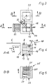
- the device 1 shown in FIG. 1 consists of a loading and unloading station 4 which has a cage carriage receiving chamber 15 and an intermediate layer station 20.
- inlet rails 5 are arranged on the cage carriage receiving chamber 15, via which a cage carriage 10 can be pushed into the cage carriage receiving chamber 15.
- Each cage carriage 10 consists of a cage 11 releasably connected to a base frame 12 by locking elements.
- the base frames 12 have wheels 13, by means of which the respective cage carriage 10 can be guided in a rolling manner on the inlet rails 5 assigned to the cage carriage receiving chamber 15.
- the cage carriage receiving chamber 15 is connected to a buffer section 6 designed as a conveying device, on the free end section of which a guide plate 7 is provided, through which containers 3 located on the buffer section 6 are fed to a conveyor 8.
- the conveyor 8 serves as a discharge conveyor during unloading and as a feed conveyor during loading. It is also possible and sufficient in many applications to design the device 1 either only as an unloading device or only as a loading device.
- Fig. 2 shows a device 2 which is suitable for continuous operation.
- the intermediate layer station 20 is arranged opposite to the buffer section 6 on the cage carriage receiving chamber 15.
- Two inlet rails 5 are guided through the cage carriage receiving chamber 15 perpendicular to the conveying direction of the buffer section 6.
- the input-side and output-side strand of the inlet rails 5 here forms a buffer zone for the cage carriage receiving chamber 15.
- a lifting fork 17 is arranged on one side of the cage carriage receiving chamber 15 and can be moved vertically and horizontally.
- the lifting fork 17 is used to hold a container arrangement 16 on each floor.
- a pusher 19 is provided on the upper end section 18 of the cage carriage receiving chamber 15, by means of which a container arrangement 16 can be moved from the respective upper intermediate layer 21 to the buffer section 6 (FIG. 4). .
- a gripper can also be provided, which is used for picking up or dispensing containers 3 on the storey level.
- an intermediate layer station 20 is arranged, which is used to store intermediate layers 21 removed from the cage car 10.
- a pivotable gripper arrangement 22 is used, which is arranged at the loading and unloading station 4 (FIG. 3).
- the intermediate layers 21 are deposited on a vertically movable lifting arrangement 23.
- This lifting arrangement can be lifting scissors 24 (FIG. 5).
- the lifting arrangement 23 can also be designed as a lifting table, the z. B. by means of a hydraulic, pneumatic or electric motor operated actuator is vertically displaceable.
- the liner station 20 is indirectly coupled to the cage carriage receiving chamber 15, the lifting arrangement 23 being located empty on the upper end section 25 of the liner station 20 and loaded in the lower section of the liner station 20.
- the lifting fork 17, the pusher 19, the gripper assembly 22 and the lifting assembly 23 are intermittently with z. B. hydraulic and / or pneumatic and / or electrical drive devices.
- a special control device not shown, is provided, which is connected to a run-in switch.
- the entry switch is located in the cage carriage receiving chamber 15 and reacts to the rolling in or rolling out of a cage carriage 10. When a cage carriage 10 rolls into the cage carriage receiving chamber 15, the cage carriage 10 is locked in the cage carriage receiving chamber 15 by measured value transmission of the entry switch.
- the lifting cables 17, the pusher 19, the gripper arrangement 22 and the lifting arrangement 23 are actuated in cycles by means of the control device until all the tier arrangements 16 on the storey side are pushed out of the respective cage 11 by means of the pusher 19 onto the buffer section 6.
- the intermediate layer 21 located below it is conveyed into the intermediate layer station 20 by means of the gripper arrangement 22.
- the lifting fork 17 automatically returns to the lower end position and the cage carriage 10 is unlocked. Thereafter, the cage carriage 10 can be led out of the cage carriage receiving chamber 15.
- the use of devices 1, 2 for loading cages 11 is carried out in the opposite manner to that described above for the unloading process.
Landscapes
- Warehouses Or Storage Devices (AREA)
Applications Claiming Priority (2)
| Application Number | Priority Date | Filing Date | Title |
|---|---|---|---|
| DE9104891U | 1991-04-22 | ||
| DE9104891U DE9104891U1 (de) | 1991-04-22 | 1991-04-22 | Vorrichtung zum Be- oder Entladen |
Publications (2)
| Publication Number | Publication Date |
|---|---|
| EP0514676A2 true EP0514676A2 (fr) | 1992-11-25 |
| EP0514676A3 EP0514676A3 (en) | 1993-07-14 |
Family
ID=6866540
Family Applications (1)
| Application Number | Title | Priority Date | Filing Date |
|---|---|---|---|
| EP19920106856 Withdrawn EP0514676A3 (en) | 1991-04-22 | 1992-04-22 | Device for loading and unloading |
Country Status (2)
| Country | Link |
|---|---|
| EP (1) | EP0514676A3 (fr) |
| DE (1) | DE9104891U1 (fr) |
Cited By (1)
| Publication number | Priority date | Publication date | Assignee | Title |
|---|---|---|---|---|
| CN108407820A (zh) * | 2018-05-09 | 2018-08-17 | 杨宗林 | 一种列车 |
Families Citing this family (2)
| Publication number | Priority date | Publication date | Assignee | Title |
|---|---|---|---|---|
| DE9104891U1 (de) * | 1991-04-22 | 1991-08-01 | Stukenbröker Maschinen- und Anlagenbau, 2850 Bremerhaven | Vorrichtung zum Be- oder Entladen |
| CN108482418B (zh) * | 2018-05-09 | 2024-04-30 | 杨宗林 | 列车乘客上下车系统 |
Family Cites Families (4)
| Publication number | Priority date | Publication date | Assignee | Title |
|---|---|---|---|---|
| DE3527746A1 (de) * | 1985-08-02 | 1987-03-05 | H & K Verpackungstechnik Gmbh | Maschine zum umsetzen von artikeln, insbesondere zum abraeumen von mit behaeltern bestueckten paletten |
| DE3536541A1 (de) * | 1985-10-12 | 1987-04-16 | Seitz Enzinger Noll Masch | Maschine zum beladen von transportierbaren paletten, container oder dgl., mit stapelbarem gut |
| FR2589139B1 (fr) * | 1985-10-24 | 1988-04-15 | Saint Gobain Emballage | Conditionnement automatique dans des recipients |
| DE9104891U1 (de) * | 1991-04-22 | 1991-08-01 | Stukenbröker Maschinen- und Anlagenbau, 2850 Bremerhaven | Vorrichtung zum Be- oder Entladen |
-
1991
- 1991-04-22 DE DE9104891U patent/DE9104891U1/de not_active Expired - Lifetime
-
1992
- 1992-04-22 EP EP19920106856 patent/EP0514676A3/de not_active Withdrawn
Cited By (2)
| Publication number | Priority date | Publication date | Assignee | Title |
|---|---|---|---|---|
| CN108407820A (zh) * | 2018-05-09 | 2018-08-17 | 杨宗林 | 一种列车 |
| CN108407820B (zh) * | 2018-05-09 | 2024-04-30 | 杨宗林 | 一种列车 |
Also Published As
| Publication number | Publication date |
|---|---|
| DE9104891U1 (de) | 1991-08-01 |
| EP0514676A3 (en) | 1993-07-14 |
Similar Documents
| Publication | Publication Date | Title |
|---|---|---|
| DE2152266C3 (de) | Fahrbare Einrichtung zum Aufnehmen bzw. Abtransport von gebrauchten Schienenbefestigungsorganen | |
| DE2841195A1 (de) | Vorrichtung zum beladen von paletten mit stueckguetern, insbesondere paketen, saecken o.dgl. | |
| DE3334769A1 (de) | Transportbehaelter sowie verfahren und vorrichtung zum transportieren von dosendeckelstapeln in dem transportbehaelter | |
| DE102011117640A1 (de) | Vorrichtung zur Stapelung und Verladung von Blechformteilen an Pressen und Pressenstraßen | |
| DE102017004410B3 (de) | Behälterwechselvorrichtung | |
| EP0010252B1 (fr) | Dispositif pour l'empilage automatique de tôles en vue de la formation de noyaux de fer feuilletés | |
| EP0161513A1 (fr) | Dispositif pour l'empilage de palettes chargées avec des objets, notamment des sacs larges | |
| EP0514676A2 (fr) | Dispositif de chargement et de déchargement | |
| DE3129388C2 (fr) | ||
| DE102022106768B4 (de) | Vorrichtung zum Manipulieren von Behältern, insbesondere bei einer Herstellung von Produkten, sowie Verwendung | |
| DE3033682C2 (de) | Vorrichtung zum Be- und/oder Entladen aus übereinandergestapelter Wandanordnung in lineare Transportanordnung | |
| DE2619156C2 (de) | Vorrichtung zum lagenweisen Entladen von Paletten | |
| DE3626977A1 (de) | Verfahren zum automatischen verpacken und entpacken von massenartikeln sowie vorrichtung zur durchfuehrung der verfahren | |
| EP0692439B1 (fr) | Procédé et installation pour l'enlèvement de palettes vides hors d'un magasin à rayonnage | |
| EP0416627A1 (fr) | Procédé et dispositif pour stocker et reprendre automatiquement des sortes de marchandises de détail de rayonnages dans de grands entrepôts | |
| DE2524919C2 (fr) | ||
| DE925039C (de) | Verfahren und Vorrichtung zum selbsttaetigen Stapeln von Ziegeln | |
| DE2716490B2 (de) | Vorrichtung zum Beladen von Paletten mit Stückgütern, insbesondere Paketen, Säcken o.dgl | |
| DE19624338C1 (de) | Prüfeinrichtung für eine Plattenwaage | |
| EP4082344B1 (fr) | Chariot de chargement des pâtons de pâte à cuire | |
| DE3027993A1 (de) | Vorrichtung zum baladen von paletten | |
| DE2236355C3 (de) | Anlage zum Beschicken von Mehretagenplattenpressen | |
| DE19738798C2 (de) | Vorrichtung für das Stapeln von Profilen | |
| AT206344B (de) | Vorrichtung zum Setzen keramischer Formlinge, insbesondere grüner oder vorgetrockneter Ziegel | |
| DE2222599A1 (de) | Einrichtung zum selbsttaetigen beladen eines hordenwagens |
Legal Events
| Date | Code | Title | Description |
|---|---|---|---|
| PUAI | Public reference made under article 153(3) epc to a published international application that has entered the european phase |
Free format text: ORIGINAL CODE: 0009012 |
|
| AK | Designated contracting states |
Kind code of ref document: A2 Designated state(s): AT DE DK GB IT NL |
|
| PUAL | Search report despatched |
Free format text: ORIGINAL CODE: 0009013 |
|
| AK | Designated contracting states |
Kind code of ref document: A3 Designated state(s): AT DE DK GB IT NL |
|
| 17P | Request for examination filed |
Effective date: 19931210 |
|
| 17Q | First examination report despatched |
Effective date: 19950428 |
|
| STAA | Information on the status of an ep patent application or granted ep patent |
Free format text: STATUS: THE APPLICATION IS DEEMED TO BE WITHDRAWN |
|
| 18D | Application deemed to be withdrawn |
Effective date: 19950909 |