EP0514816A1 - Engagement dynamique d'un vis-ecrou avec détection d'engagement - Google Patents
Engagement dynamique d'un vis-ecrou avec détection d'engagement Download PDFInfo
- Publication number
- EP0514816A1 EP0514816A1 EP92108366A EP92108366A EP0514816A1 EP 0514816 A1 EP0514816 A1 EP 0514816A1 EP 92108366 A EP92108366 A EP 92108366A EP 92108366 A EP92108366 A EP 92108366A EP 0514816 A1 EP0514816 A1 EP 0514816A1
- Authority
- EP
- European Patent Office
- Prior art keywords
- engagement
- threads
- lead screw
- screw
- plunger
- Prior art date
- Legal status (The legal status is an assumption and is not a legal conclusion. Google has not performed a legal analysis and makes no representation as to the accuracy of the status listed.)
- Granted
Links
- 230000007246 mechanism Effects 0.000 claims abstract description 62
- 238000000034 method Methods 0.000 claims description 5
- 230000004044 response Effects 0.000 claims description 4
- 238000001802 infusion Methods 0.000 description 5
- 230000003287 optical effect Effects 0.000 description 5
- 230000003213 activating effect Effects 0.000 description 4
- 239000012530 fluid Substances 0.000 description 4
- 239000003978 infusion fluid Substances 0.000 description 4
- 238000010586 diagram Methods 0.000 description 2
- 230000008878 coupling Effects 0.000 description 1
- 238000010168 coupling process Methods 0.000 description 1
- 238000005859 coupling reaction Methods 0.000 description 1
- 230000001351 cycling effect Effects 0.000 description 1
- 238000001514 detection method Methods 0.000 description 1
- 238000012986 modification Methods 0.000 description 1
- 230000004048 modification Effects 0.000 description 1
- 230000000284 resting effect Effects 0.000 description 1
Images



Classifications
-
- A—HUMAN NECESSITIES
- A61—MEDICAL OR VETERINARY SCIENCE; HYGIENE
- A61M—DEVICES FOR INTRODUCING MEDIA INTO, OR ONTO, THE BODY; DEVICES FOR TRANSDUCING BODY MEDIA OR FOR TAKING MEDIA FROM THE BODY; DEVICES FOR PRODUCING OR ENDING SLEEP OR STUPOR
- A61M5/00—Devices for bringing media into the body in a subcutaneous, intra-vascular or intramuscular way; Accessories therefor, e.g. filling or cleaning devices, arm-rests
- A61M5/14—Infusion devices, e.g. infusing by gravity; Blood infusion; Accessories therefor
- A61M5/142—Pressure infusion, e.g. using pumps
- A61M5/145—Pressure infusion, e.g. using pumps using pressurised reservoirs, e.g. pressurised by means of pistons
- A61M5/1452—Pressure infusion, e.g. using pumps using pressurised reservoirs, e.g. pressurised by means of pistons pressurised by means of pistons
- A61M5/1456—Pressure infusion, e.g. using pumps using pressurised reservoirs, e.g. pressurised by means of pistons pressurised by means of pistons with a replaceable reservoir comprising a piston rod to be moved into the reservoir, e.g. the piston rod is part of the removable reservoir
-
- F—MECHANICAL ENGINEERING; LIGHTING; HEATING; WEAPONS; BLASTING
- F16—ENGINEERING ELEMENTS AND UNITS; GENERAL MEASURES FOR PRODUCING AND MAINTAINING EFFECTIVE FUNCTIONING OF MACHINES OR INSTALLATIONS; THERMAL INSULATION IN GENERAL
- F16H—GEARING
- F16H25/00—Gearings comprising primarily only cams, cam-followers and screw-and-nut mechanisms
- F16H25/18—Gearings comprising primarily only cams, cam-followers and screw-and-nut mechanisms for conveying or interconverting oscillating or reciprocating motions
- F16H25/20—Screw mechanisms
- F16H25/2025—Screw mechanisms with means to disengage the nut or screw from their counterpart; Means for connecting screw and nut for stopping reciprocating movement
-
- A—HUMAN NECESSITIES
- A61—MEDICAL OR VETERINARY SCIENCE; HYGIENE
- A61M—DEVICES FOR INTRODUCING MEDIA INTO, OR ONTO, THE BODY; DEVICES FOR TRANSDUCING BODY MEDIA OR FOR TAKING MEDIA FROM THE BODY; DEVICES FOR PRODUCING OR ENDING SLEEP OR STUPOR
- A61M5/00—Devices for bringing media into the body in a subcutaneous, intra-vascular or intramuscular way; Accessories therefor, e.g. filling or cleaning devices, arm-rests
- A61M5/14—Infusion devices, e.g. infusing by gravity; Blood infusion; Accessories therefor
- A61M5/142—Pressure infusion, e.g. using pumps
- A61M5/145—Pressure infusion, e.g. using pumps using pressurised reservoirs, e.g. pressurised by means of pistons
- A61M5/1452—Pressure infusion, e.g. using pumps using pressurised reservoirs, e.g. pressurised by means of pistons pressurised by means of pistons
- A61M2005/14573—Pressure infusion, e.g. using pumps using pressurised reservoirs, e.g. pressurised by means of pistons pressurised by means of pistons with a replaceable reservoir for quick connection/disconnection with a driving system
-
- Y—GENERAL TAGGING OF NEW TECHNOLOGICAL DEVELOPMENTS; GENERAL TAGGING OF CROSS-SECTIONAL TECHNOLOGIES SPANNING OVER SEVERAL SECTIONS OF THE IPC; TECHNICAL SUBJECTS COVERED BY FORMER USPC CROSS-REFERENCE ART COLLECTIONS [XRACs] AND DIGESTS
- Y10—TECHNICAL SUBJECTS COVERED BY FORMER USPC
- Y10S—TECHNICAL SUBJECTS COVERED BY FORMER USPC CROSS-REFERENCE ART COLLECTIONS [XRACs] AND DIGESTS
- Y10S128/00—Surgery
- Y10S128/01—Motorized syringe
Definitions
- the invention is related generally to screw drive mechanisms, and more particularly, to a lead screw engagement system.
- the infusion of fluids such as parenteral fluids into the human body is accomplished in many cases by means of a syringe pump having a lead screw on which a screw drive mechanism is mounted. Rotation of the lead screw is translated into linear motion by the screw drive mechanism and is transmitted to the syringe plunger by a plunger driver.
- the plunger driver is typically rigidly connected to the screw drive mechanism.
- a split nut or half nut is used as part of the screw drive mechanism in some pumps for easy and rapid repositioning of the screw drive mechanism and plunger driver on the lead screw to engage a new syringe plunger.
- An activating lever or other mechanical interface may be provided at the plunger driver to separate the split nut from the lead screw threads and to disengage the plunger driver from the present syringe plunger.
- the plunger driver is retracted and the syringe replaced.
- the operator uses the activating lever or other mechanical interface to disengage the split nut from the lead screw, moves the plunger driver and split nut along the lead screw to the appropriate position and inserts the new syringe plunger.
- the operator then releases the activating lever to clamp the plunger driver onto the new plunger and to engage the lead screw threads with the split nut.
- re-engagement with the lead screw threads does not always occur at this time due to the shape of the thread profile.
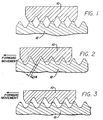
- the crests of the threads 10 of the split nut align with and contact the crests of the threads 12 of the lead screw rather than the threads engaging each other. Because these threads may be relatively flat at their crests, they do not engage each other until the lead screw has turned a sufficient amount and the bias device of the screw drive mechanism has forced the threads of the split nut to drop into or engage the lead screw threads. Under low infusion rates, such sufficient lead screw rotation may take a substantial amount of time, this time then being a period during which the patient does not receive the infusion fluid.
- the non-driving surfaces of the threads 10 of the split nut may contact the non-driving surfaces of the threads 12 of the lead screw when the activating lever is released.
- the arrow indicates the direction of forward movement of the split nut and plunger driver. Due to the thread clearance 14 between the two sets of threads, some amount of time may pass before the driving surfaces of the lead screw threads 12 contact the driving surfaces of the split nut threads 10 and actually begin to move the split nut and plunger driver. This also would be a time period during which the patient receives no infusion fluids.
- the threads 10 of the split nut may have only partially engaged the threads 12 of the lead screw. If this should happen on the driving surfaces of the threads of the lead screw as shown, the threads 10 of the split-nut may not drop into the threads 12 of the lead screw because of the large amount of back pressure provided by the full syringe and because of the force vector developed by the lead screw threads which tends to force the split nut threads 10 up and out of the lead screw threads 12. If the biasing force on the split nut is not strong enough to overcome all of these factors, the split nut threads 10 may be forced out of contact with the driving surfaces of the threads 12 of the lead screw and into the position shown in FIG. 1. This case would likewise result in a time period during which the patient would not receive the infusion fluid and this time period may exceed that associated with FIG. 1.
- the case shown in FIG. 3 may be indicated as thread engagement.
- the detector monitors the position of the lever used by the operator at the plunger driver rather than the engagement mechanism at the lead screw itself. And in some cases, these levers are coupled to the split nut through a spring rather than through a rigid mechanical connection. Where the lever is in the correct position for engagement of the screw drive mechanism with the lead screw but the spring coupling has not transmitted the lever force to the split nut, an inaccurate indication of screw engagement may be given with a resulting time period during which the patient receives no infusion fluid.
- an engagement system for engaging the threads of a lead screw with the threads of a screw drive mechanism, the screw drive mechanism operating to translate the rotational motion of the lead screw into linear motion
- the system comprising: a motor coupled to the lead screw which selectively rotates the lead screw; an engagement mechanism mounted to the screw drive mechanism to selectively move the screw drive mechanism threads into and out of engagement with the threads of the lead screw; an engagement detector which senses the position of the engagement mechanism and provides an engagement signal representative of the engagement mechanism being in a position to cause engagement of the threads of the screw drive mechanism with the threads of the lead screw; and a processor which receives the engagement signal and controls the motor to cause the lead screw to rotate for a predetermined time period when the engagement signal indicates that the threads are not engaged.
- the present invention provides for the automatic engagement of a lead screw drive mechanism with a lead screw.
- a plunger driver used to move the plunger of an inserted syringe.
- the screw drive mechanism includes an engagement mechanism which causes the threads of the screw drive mechanism to selectively engage and disengage the threads of the lead screw.
- An engagement detector is used to determine the position of the engagement mechanism and provides a signal representative of its position as regards engagement of the threads.
- a second detector provides a plunger signal indicating the presence of a syringe plunger in the plunger driver.
- a processor receives the plunger signal and the thread engagement signal and provides a signal to the motor controller to cause the motor to rotate the lead screw in response thereto.
- the processor causes the motor to rotate the screw in a forward direction by a first predetermined amount to remove the thread clearance.
- the processor causes the motor to rotate first in a reverse direction for a second predetermined amount and then in a forward direction for a third predetermined amount to cause engagement of the threads.
- the processor will then continue reverse rotation for an additional predetermined distance to fully seat the threads. For this condition, the threads are already on the driving surfaces and the thread clearance has been removed.
- the processor will continue forward rotation for an additional predetermined distance to fully seat the threads and remove thread clearance. The processor will then await further pump operation instructions.
- the cycle of reverse and then forward rotation of the lead screw is limited in the distance of travel along the lead screw.
- the cycle of reverse/forward screw rotation may be repeated a limited number of times to attempt to attain screw engagement. Failure to attain engagement within the limit results in an unengaged system.
- the engagement detector is mounted to detect the position of the engagement mechanism which is rigidly connected to the threads of the screw drive mechanism.
- the detector is thus connected to the actual mechanical connection to the threads and is therefore more reliable and more accurate in determining actual engagement.
- the trip point of the detector is selected to be at a point which is less than fifty percent of the root thread depth thereby assuring that a "threads engaged" signal indicates that the threads are engaged sufficiently to cause a movement of the plunger driver.
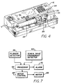
- FIG. 4 a syringe pump 16 having a syringe 18 partially installed and a plunger driver 20.
- the plunger driver 20 includes a plunger detector button 22 which is used to detect the presence of a syringe plunger 24 engaged with the plunger driver 20.
- the syringe plunger 24 is not engaged with the plunger driver so that the detector button 22 may be seen.
- FIG. 5 an exploded view of a plunger driver is shown.
- the front housing 26 has been separated from the rear housing 28 to view the plunger detector in more detail.
- the detector button 22 has been withdrawn from its normal position in the front housing 26.
- the button 22 has a beveled front surface 30 to allow additional flexibility in loading the syringe.
- the button has a spring 32 to provide a bias of the button outward toward the syringe plunger. In this embodiment, the spring rests against the rear housing 28 to push the button 22 to extend out of the front housing through aperture 34.
- the button includes an annular stop flange 33 to retain the button in the housing. The button will extend through the aperture 34 formed in the front housing to press against an inserted syringe plunger 24 (FIG. 1).
- the button 22 also includes a flag 36 for indicating the button's position and that of the syringe plunger.
- An optical beam detector 38 is mounted above the button 22 but in line with the flag 36 to determine the position of the flag. In this embodiment, should the button be extended as far forward as possible, the flag 36 will interrupt the beam of the optical beam detector 38 and the detector will provide a signal indicating that no plunger is present. As shown, the plunger driver 20 is connected to a split nut tube 40.
- the screw drive mechanism 44 includes the split nut tube 40 having a flange 41 on which is mounted a pin 46 for engaging a cam plate 48.
- the cam plate 48 includes two slots 50, each for engaging a pin on a respective split nut 52 half.
- the split nut 52 and cam plate 50 are sandwiched between the support plate 53 and the split nut housing 54 and held in position by screws 56.
- the split nut tube 40 includes a flag 58 rigidly mounted on the flange 41 and the pin 46 and this flag 58 will rotate with the rotation of the tube 40.
- the pin 46 on the flange 41 engages the upper slot 47 in the cam plate 50 and thereby rotates the cam plate, and that cam plate will cause motion of the split nut 52 into and out of engagement with the lead screw 42.
- This arrangement results in a nonlinear movement of the split nut as will be discussed in more detail following.
- the position of the flag 58 will be representative of split nut engagement with the lead screw 42.
- an optical beam detector 60 is mounted on a flange 62 forming part of the split nut housing 54 and detects the position of the flag 58.
- the optical detector 60 provides a thread engagement signal representative of that detection. In the embodiment of FIG. 6, interruption of the beam by the flag 58 will indicate that the split nut 52 is disengaged from the lead screw 42.
- the support plate 53 is in threaded engagement with the lead screw 42 and will exhibit linear motion as a response to lead screw rotation.
- the split nut tube 40 and the drive tube 64 (not shown in FIG. 5) rigidly couple the screw drive mechanism 44 to the plunger driver 20.
- the plunger driver 20 will move with the screw drive mechanism 44.
- Rotation of the split-nut tube 40 and the resulting movement of the split nut halves results from movement of the lever 45 shown in FIGS. 4 and 5.
- the lever 45 is coupled to the split nut tube 40 as shown in FIG. 5.
- the flag 58 and detector 60 are immediately and rigidly coupled to the engagement mechanism which causes the halves of the split nut to move. This results in more accurate and more reliable operation of determining thread engagement.
- the detector signals from the plunger detector 38 and from the screw drive engagement detector 60 are coupled to a processor 66.
- the processor analyzes these signals and based on various factors as discussed below, will provide a signal to the motor control or a flashing indicator 70.
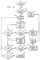
- the plunger detector signal is analyzed and if the signal indicates that a plunger is present, the engagement detector 60 signal is analyzed 73 to determine if the threads are engaged. If the threads are engaged, the processor 66 causes forward rotation 74 of the motor 69 to remove any thread clearance which may exist between the threads as shown in FIG. 2. In one case where the pitch of the threads was 0.050 inches (1.27 mm), the motor would turn the lead screw by an amount equal to 0.00064 in. (0.0162 mm) of travel along the lead screw which is the distance between the slope of the threads. This would then remove all thread clearance and the driving surfaces of the lead screw threads would be in contact with the driving surfaces of the split nut threads. When the pump is thereafter energized to begin infusion, fluid will immediately flow. The pump is then ready for infusion 75.
- the processor 66 would then set 76 a count equal to "X" which may be a count of flags coupled to motor rotation or drive gear rotation or some other measure of distance along the lead screw, and then cause the motor to run in reverse while decrementing the count 77.
- the screw drive engagement detector 60 signal is analyzed 78 to determine if the threads are engaged, and if they are, the motor is run in reverse 79 for some further time to fully seat the threads. The motor need not be run forward at this time because the driving surfaces of the threads of the lead screw will be against the driving surfaces of the split nut.
- the pump is now ready 75.
- the count is analyzed 80 and if not less than or equal to zero, reverse running of the motor is continued 77 until the count does equal or is less than zero or the threads become engaged. If they still do not engage, the motor is run in forward and the count incremented 82.
- the engagement detector 60 signal is analyzed 84 to determine if the threads are engaged, and if they are, the motor is run in forward 85 by an amount of twice the thread clearance plus a tolerance amount, which in one embodiment was 0.003 inches (0.076 mm). The pump is then ready 75.
- the count is analyzed 86 and if less than "Y", forward running of the motor is continued 82 until the count does exceed Y or the threads become engaged. If they still do not engage, the number of cycles of reverse/forward running is analyzed 87 and if equal to or greater than two, the thread engagement is considered unsuccessful 89 and a flashing indicator 90 (FIG. 4) continues to be energized. If the cycle count is under two, it is repeated.
- the counts "X" and "Y”, are set to result in travel along the lead screw of approximately 0.025 in. (0.635 mm). In this embodiment, these distances correspond to the distance of the length of the crest of one lead screw thread plus the distance of the crest of one split nut thread plus a tolerance amount.
- a limit on the number of cycles of forward/reverse rotation is imposed.
- the limit is two cycles.
- Another limit which may be imposed is a time limit.
- the processor may limit the forward/reverse cycling to a total of five seconds. Other limits are possible.
- the flag 58 is placed on the same flange 41 that houses the pin 46 used to move the cam plate 50 to separate the split nut 52.
- a direct, rigid and immediate mechanical connection exists between the detector 60 of thread engagement and the means to cause that engagement. Both are located on the same flange 41. This results in a highly reliable and more accurate system for indicating thread engagement as opposed to prior systems which monitor the movement of the lever as discussed above.
- a curve of split nut 52 travel versus split nut tube 40 angle is provided.
- the root thread depth of the lead screw and the split-nut is approximately 0.032 in. (0.825 mm).
- the split nut and lead screw should begin engagement at approximately 0.059 in. (1.50 mm) in this embodiment.
- the vertical axis represents distance from the center of the lead screw and the horizontal axis represents the angle of rotation of the split nut tube 40. Because a cam plate 48 is used with the pin 46 as shown, a nonlinear curve results and the trip point 94 of the optical detector 60 can be located on the shallow part of the curve which is much less sensitive to the tolerances of the parts than at the steeper part of the curve.
- the trip point 94 also allows the trip point 94 to be set at a low depth to more accurately indicate actual thread engagement.
- the depth of the trip point 94 is 0.003 inches (0.076 mm) which is less than the root thread depth.
- the root thread depth 95 is approximately 0.032 inches (0.813 mm). It has been found that setting the trip point no higher than fifty percent of the root thread depth results in greater accuracy. In the case shown in FIG. 9, that point would be at approximately 0.016 in. (0.406 mm).
- FIGS. 10a and 10b the sequence of a split-nut 52 and lead screw 42 thread engagement can be seen.
- the split-nut 52 and lead screw 42 are disengaged from each other.
- the dashed lines indicate root thread depth.
- FIG. 10b some engagement has occurred, but due to the configuration of the split-nut, engagement only at the extremities of the respective halves of the split-nut has occurred. This point of engagement is indicated as numeral 92 in FIG. 9.
- the main portion of the split-nut threads has not engaged with the lead screw threads.
- the threads may disengage from each other if a large load is experienced by the plunger driver. Therefore, it is desirable to indicate engagement at a much lower point on the curve shown in FIG. 9. This has been done at point 94 as discussed above.
- the engagement system and method in accordance with the principles of the invention provides a positive and rapid way of engaging the lead screw with the screw drive mechanism.
- the use of a screw drive engagement detector in accordance with the invention results in a more accurate and reliable indication of actual thread engagement.
Landscapes
- Health & Medical Sciences (AREA)
- Engineering & Computer Science (AREA)
- General Engineering & Computer Science (AREA)
- Biomedical Technology (AREA)
- Vascular Medicine (AREA)
- Anesthesiology (AREA)
- Mechanical Engineering (AREA)
- Heart & Thoracic Surgery (AREA)
- Hematology (AREA)
- Life Sciences & Earth Sciences (AREA)
- Animal Behavior & Ethology (AREA)
- General Health & Medical Sciences (AREA)
- Public Health (AREA)
- Veterinary Medicine (AREA)
- Infusion, Injection, And Reservoir Apparatuses (AREA)
Applications Claiming Priority (2)
| Application Number | Priority Date | Filing Date | Title |
|---|---|---|---|
| US704337 | 1991-05-23 | ||
| US07/704,337 US5106375A (en) | 1991-05-23 | 1991-05-23 | Dynamic lead screw engagement and indicator |
Publications (2)
| Publication Number | Publication Date |
|---|---|
| EP0514816A1 true EP0514816A1 (fr) | 1992-11-25 |
| EP0514816B1 EP0514816B1 (fr) | 1996-11-20 |
Family
ID=24829054
Family Applications (1)
| Application Number | Title | Priority Date | Filing Date |
|---|---|---|---|
| EP92108366A Expired - Lifetime EP0514816B1 (fr) | 1991-05-23 | 1992-05-18 | Engagement dynamique d'un vis-ecrou avec détection d'engagement |
Country Status (3)
| Country | Link |
|---|---|
| US (1) | US5106375A (fr) |
| EP (1) | EP0514816B1 (fr) |
| DE (1) | DE69215270T2 (fr) |
Cited By (7)
| Publication number | Priority date | Publication date | Assignee | Title |
|---|---|---|---|---|
| WO1996023535A1 (fr) * | 1995-02-03 | 1996-08-08 | Graseby Medical Limited | Mecanisme d'entraînement |
| WO2002051474A1 (fr) * | 2000-12-22 | 2002-07-04 | Dca Design International Limited | Mecanisme d'entrainement destine a un dispositif d'injection |
| EP1704883A1 (fr) * | 2005-03-24 | 2006-09-27 | Disetronic Licensing AG | Dispositif pour la distribution dosée d'un produit fluide |
| EP1704885A1 (fr) * | 2005-03-24 | 2006-09-27 | Disetronic Licensing AG | Dispositif pour la distribution dosée d'un produit fluide |
| EP1704886A1 (fr) * | 2005-03-24 | 2006-09-27 | Disetronic Licensing AG | Dispositif pour la distribution dosée d'un produit fluide |
| EP1704884A1 (fr) * | 2005-03-24 | 2006-09-27 | Disetronic Licensing AG | Dispositif pour la distribution dosée d'un produit fluide |
| US7543516B2 (en) | 2005-07-22 | 2009-06-09 | Cardinal Health 303, Inc. | Dynamic lead screw thread engagement system and method |
Families Citing this family (27)
| Publication number | Priority date | Publication date | Assignee | Title |
|---|---|---|---|---|
| US5232449A (en) * | 1992-04-29 | 1993-08-03 | Becton, Dickinson And Company | Syringe pump pusher |
| US5261884A (en) * | 1992-04-29 | 1993-11-16 | Becton, Dickinson And Company | Syringe pump control system |
| US5254096A (en) * | 1992-09-23 | 1993-10-19 | Becton, Dickinson And Company | Syringe pump with graphical display or error conditions |
| JP3193281B2 (ja) | 1995-10-31 | 2001-07-30 | テルモ株式会社 | シリンジポンプ |
| CA2259442C (fr) * | 1996-07-01 | 2006-06-06 | Pharmacia & Upjohn Ab | Dispositif d'injection et procede de fonctionnement dudit dispositif |
| JP3874484B2 (ja) * | 1997-03-05 | 2007-01-31 | スーガン株式会社 | 医療用インジェクタヘッド |
| US6726650B2 (en) * | 1997-12-04 | 2004-04-27 | Bracco Research S.A. | Automatic liquid injection system and method |
| CA2409711A1 (fr) * | 2000-05-18 | 2001-11-22 | Dentsply International, Inc. | Seringue distributrice de matiere fluide |
| EP1324789B1 (fr) * | 2000-10-10 | 2006-05-03 | Dentsply International, Inc. | Seringue d'anesthésie dentaire |
| JP2003070909A (ja) * | 2001-08-30 | 2003-03-11 | Japan Servo Co Ltd | 輸液装置 |
| US7041082B2 (en) | 2002-02-28 | 2006-05-09 | Smiths Medical Md, Inc. | Syringe pump control systems and methods |
| US7033338B2 (en) * | 2002-02-28 | 2006-04-25 | Smiths Medical Md, Inc. | Cartridge and rod for axially loading medication pump |
| JP4286019B2 (ja) * | 2003-02-04 | 2009-06-24 | 株式会社根本杏林堂 | 薬液注入システム |
| US8422413B2 (en) * | 2003-09-18 | 2013-04-16 | Dentsply International Inc. | Process and device for the wireless transmission of dental process data |
| ES2555125T3 (es) * | 2004-02-18 | 2015-12-29 | Ares Trading S.A. | Dispositivo manual de inyección controlada electrónicamente para inyectar medicamentos líquidos |
| ITMO20040086A1 (it) * | 2004-04-20 | 2004-07-20 | Gambro Lundia Ab | Metodo per controllare un dispositivo di infusione. |
| CN101115516A (zh) * | 2005-02-21 | 2008-01-30 | 诺和诺德公司 | 确保注射设备中的电动机的恒速的方法 |
| US8167846B2 (en) * | 2009-07-08 | 2012-05-01 | Medtronic Minimed, Inc. | Reservoir filling systems and methods |
| US8932256B2 (en) | 2009-09-02 | 2015-01-13 | Medtronic Minimed, Inc. | Insertion device systems and methods |
| WO2011064615A1 (fr) * | 2009-11-24 | 2011-06-03 | Tecres S.P.A. | Dispositif goutte-à-goutte pour fluides médicaux et autres |
| US11497850B2 (en) | 2009-12-30 | 2022-11-15 | Medtronic Minimed, Inc. | Connection and alignment detection systems and methods |
| US9744300B2 (en) * | 2011-12-21 | 2017-08-29 | Deka Products Limited Partnership | Syringe pump and related method |
| US9295778B2 (en) * | 2011-12-21 | 2016-03-29 | Deka Products Limited Partnership | Syringe pump |
| DE102013214221B3 (de) * | 2013-04-09 | 2014-06-18 | Johnson Controls Gmbh | Vorrichtung und Verfahren zur Blockierung einer Schnellverstellung einer Gewindespindel |
| WO2016204953A1 (fr) * | 2015-06-16 | 2016-12-22 | Skytran Inc. | Dispositif et système d'entraînement linéaire magnétique |
| EP3359226B1 (fr) * | 2015-10-05 | 2024-12-04 | Fresenius Vial SAS | Dispositif de perfusion permettant d'administrer un fluide médical à un patient et procédé pour faire fonctionner un dispositif de perfusion |
| JP7427858B2 (ja) * | 2019-03-07 | 2024-02-06 | 株式会社トップ | 送りねじクラッチ機構 |
Citations (3)
| Publication number | Priority date | Publication date | Assignee | Title |
|---|---|---|---|---|
| US4189950A (en) * | 1976-08-09 | 1980-02-26 | Keystone International, Inc. | Manual control apparatus |
| WO1982001998A1 (fr) * | 1980-12-15 | 1982-06-24 | Corp Ivac | Mecanisme de vissage et d'engagement/liberation d'un piston de seringue |
| EP0314880A2 (fr) * | 1987-11-04 | 1989-05-10 | B. Braun Melsungen AG | Appareil de perfusion sous pression |
Family Cites Families (29)
| Publication number | Priority date | Publication date | Assignee | Title |
|---|---|---|---|---|
| DE1447355B2 (de) * | 1963-01-22 | 1970-05-21 | M. Hensoldt & Söhne, Optische Werke AG, 6330 Wetzlar | Vorrichtung zur schrittweisen Verstellung eines Schlittens |
| US3701345A (en) * | 1970-09-29 | 1972-10-31 | Medrad Inc | Angiographic injector equipment |
| GB1369594A (en) * | 1970-09-30 | 1974-10-09 | Cambridge Scientific Instr Ltd | Scientific instruments |
| US3720211A (en) * | 1971-08-18 | 1973-03-13 | G Kyrias | Automatic injection system |
| US3842690A (en) * | 1973-05-10 | 1974-10-22 | Res Eng Co | Automatically disengageable manual control |
| US3858581A (en) * | 1973-07-02 | 1975-01-07 | Dean Kamen | Medication injection device |
| US3886938A (en) * | 1973-10-23 | 1975-06-03 | Scala Anthony | Power operated fluid infusion device |
| US4023431A (en) * | 1975-05-05 | 1977-05-17 | Bettis Corporation | Spring loaded split nut |
| US4048897A (en) * | 1976-05-10 | 1977-09-20 | Price Jr Ellie Edward | Laterally engagable and releasable nut assembly |
| GB1595972A (en) * | 1977-03-09 | 1981-08-19 | Nat Res Dev | Syringe driving apparatus |
| IT1144743B (it) * | 1981-07-09 | 1986-10-29 | Mario Cane | Apparecchio infusore di insulina perfezionato |
| DE8137235U1 (de) * | 1981-12-21 | 1982-05-19 | B. Braun Melsungen Ag, 3508 Melsungen | Druckinfussionsapparat fuer medizinische anwendungen |
| US4435173A (en) * | 1982-03-05 | 1984-03-06 | Delta Medical Industries | Variable rate syringe pump for insulin delivery |
| DE3314664C2 (de) * | 1983-04-22 | 1985-02-21 | B. Braun Melsungen Ag, 3508 Melsungen | Verfahren zur Auslösung von Voralarm bei einem Druckinfusionsapparat |
| US4544369A (en) * | 1983-11-22 | 1985-10-01 | C. R. Bard, Inc. | Battery operated miniature syringe infusion pump |
| US4685903A (en) * | 1984-01-06 | 1987-08-11 | Pacesetter Infusion, Ltd. | External infusion pump apparatus |
| US4908017A (en) * | 1985-05-14 | 1990-03-13 | Ivion Corporation | Failsafe apparatus and method for effecting syringe drive |
| GB8525109D0 (en) * | 1985-10-11 | 1985-11-13 | Vickers Plc | Syringe pumps |
| US4731058A (en) * | 1986-05-22 | 1988-03-15 | Pharmacia Deltec, Inc. | Drug delivery system |
| US4804368A (en) * | 1986-12-05 | 1989-02-14 | C. R. Bard, Inc. | Battery operated miniature syringe infusion pump and improved halfnut therefor |
| US4919650A (en) * | 1987-03-30 | 1990-04-24 | Bionica Pty. Limited | Infusion pump |
| EP0285679A1 (fr) * | 1987-04-04 | 1988-10-12 | B. Braun-SSC AG | Appareil de perfusion sous pression |
| US5034004A (en) * | 1987-06-19 | 1991-07-23 | The University Of Melbourne | Infusion pump and drive systems therefor |
| DE3739563C1 (de) * | 1987-11-22 | 1989-04-13 | Fresenius Ag | Infusionsspritzenpumpe |
| US4959056A (en) * | 1988-06-14 | 1990-09-25 | Wayne State University | Digital dispenser |
| US4883101A (en) * | 1988-06-27 | 1989-11-28 | Jordan Enterprises | Filling device with sound indicator for filling injection syringe |
| JP2717808B2 (ja) * | 1988-08-10 | 1998-02-25 | テルモ株式会社 | シリンジポンプ |
| DE3838465A1 (de) * | 1988-11-12 | 1990-05-17 | Fresenius Ag | Spritzenpumpe |
| GB2229497B (en) * | 1989-03-10 | 1992-06-03 | Graseby Medical Ltd | Infusion pump |
-
1991
- 1991-05-23 US US07/704,337 patent/US5106375A/en not_active Expired - Lifetime
-
1992
- 1992-05-18 DE DE69215270T patent/DE69215270T2/de not_active Expired - Lifetime
- 1992-05-18 EP EP92108366A patent/EP0514816B1/fr not_active Expired - Lifetime
Patent Citations (3)
| Publication number | Priority date | Publication date | Assignee | Title |
|---|---|---|---|---|
| US4189950A (en) * | 1976-08-09 | 1980-02-26 | Keystone International, Inc. | Manual control apparatus |
| WO1982001998A1 (fr) * | 1980-12-15 | 1982-06-24 | Corp Ivac | Mecanisme de vissage et d'engagement/liberation d'un piston de seringue |
| EP0314880A2 (fr) * | 1987-11-04 | 1989-05-10 | B. Braun Melsungen AG | Appareil de perfusion sous pression |
Cited By (14)
| Publication number | Priority date | Publication date | Assignee | Title |
|---|---|---|---|---|
| GB2301419A (en) * | 1995-02-03 | 1996-12-04 | Graseby Medical Ltd | Drive mechanism |
| WO1996023535A1 (fr) * | 1995-02-03 | 1996-08-08 | Graseby Medical Limited | Mecanisme d'entraînement |
| CN1292807C (zh) * | 2000-12-22 | 2007-01-03 | Dca设计国际有限公司 | 用于注射装置的驱动机构 |
| WO2002051474A1 (fr) * | 2000-12-22 | 2002-07-04 | Dca Design International Limited | Mecanisme d'entrainement destine a un dispositif d'injection |
| WO2002051471A1 (fr) * | 2000-12-22 | 2002-07-04 | Dca Design International Limited | Mecanisme d'entrainement pour un dispositif d'injection |
| US6969370B2 (en) | 2000-12-22 | 2005-11-29 | Dca Design International Limited | Drive mechanism for an injection device |
| US7052484B2 (en) | 2000-12-22 | 2006-05-30 | Robert Frederick Veasey | Drive mechanism for an injection device |
| US8926553B2 (en) | 2000-12-22 | 2015-01-06 | Christopher Nigel Langley | Pen-type injector having an electronic control unit |
| CN1325127C (zh) * | 2000-12-22 | 2007-07-11 | Dca设计国际有限公司 | 用于注射装置的驱动机构 |
| EP1704883A1 (fr) * | 2005-03-24 | 2006-09-27 | Disetronic Licensing AG | Dispositif pour la distribution dosée d'un produit fluide |
| EP1704884A1 (fr) * | 2005-03-24 | 2006-09-27 | Disetronic Licensing AG | Dispositif pour la distribution dosée d'un produit fluide |
| EP1704886A1 (fr) * | 2005-03-24 | 2006-09-27 | Disetronic Licensing AG | Dispositif pour la distribution dosée d'un produit fluide |
| EP1704885A1 (fr) * | 2005-03-24 | 2006-09-27 | Disetronic Licensing AG | Dispositif pour la distribution dosée d'un produit fluide |
| US7543516B2 (en) | 2005-07-22 | 2009-06-09 | Cardinal Health 303, Inc. | Dynamic lead screw thread engagement system and method |
Also Published As
| Publication number | Publication date |
|---|---|
| DE69215270D1 (de) | 1997-01-02 |
| DE69215270T2 (de) | 1997-05-22 |
| US5106375A (en) | 1992-04-21 |
| EP0514816B1 (fr) | 1996-11-20 |
Similar Documents
| Publication | Publication Date | Title |
|---|---|---|
| US5106375A (en) | Dynamic lead screw engagement and indicator | |
| US4988337A (en) | Syringe pump apparatus | |
| US7543516B2 (en) | Dynamic lead screw thread engagement system and method | |
| EP1526884B1 (fr) | Systeme de commande de plongeur pour seringues | |
| EP0589328B1 (fr) | Pompe-seringue avec affichage graphique des conditions d'erreur | |
| CA1277179C (fr) | Dispositif pour deplacer un piston dans une chambre | |
| US5545140A (en) | Syringe plunger driver | |
| CA1176934A (fr) | Mecanisme d'avance et de retrait filete pour piston de seringue | |
| EP1110569B1 (fr) | Pompe seringue | |
| GB2350796A (en) | Syringe pump with means to detect whether the position of the syringe is correct | |
| EP0402553B1 (fr) | Pousse-seringue | |
| AU2007203388B2 (en) | Syringe plunger driver system | |
| CN121944294A (zh) | 具有制动装置的输注装置 | |
| HK1116110B (en) | Dynamic lead screw thread engagement system and method | |
| HK1076060B (en) | Syringe plunger driver system |
Legal Events
| Date | Code | Title | Description |
|---|---|---|---|
| PUAI | Public reference made under article 153(3) epc to a published international application that has entered the european phase |
Free format text: ORIGINAL CODE: 0009012 |
|
| AK | Designated contracting states |
Kind code of ref document: A1 Designated state(s): DE FR GB |
|
| 17P | Request for examination filed |
Effective date: 19930323 |
|
| 17Q | First examination report despatched |
Effective date: 19941208 |
|
| GRAG | Despatch of communication of intention to grant |
Free format text: ORIGINAL CODE: EPIDOS AGRA |
|
| GRAH | Despatch of communication of intention to grant a patent |
Free format text: ORIGINAL CODE: EPIDOS IGRA |
|
| GRAH | Despatch of communication of intention to grant a patent |
Free format text: ORIGINAL CODE: EPIDOS IGRA |
|
| RAP1 | Party data changed (applicant data changed or rights of an application transferred) |
Owner name: IVAC MEDICAL SYSTEMS, INC. |
|
| GRAA | (expected) grant |
Free format text: ORIGINAL CODE: 0009210 |
|
| AK | Designated contracting states |
Kind code of ref document: B1 Designated state(s): DE FR GB |
|
| REF | Corresponds to: |
Ref document number: 69215270 Country of ref document: DE Date of ref document: 19970102 |
|
| ET | Fr: translation filed | ||
| RAP2 | Party data changed (patent owner data changed or rights of a patent transferred) |
Owner name: IVAC MEDICAL SYSTEMS, INC. |
|
| PLBE | No opposition filed within time limit |
Free format text: ORIGINAL CODE: 0009261 |
|
| STAA | Information on the status of an ep patent application or granted ep patent |
Free format text: STATUS: NO OPPOSITION FILED WITHIN TIME LIMIT |
|
| 26N | No opposition filed | ||
| REG | Reference to a national code |
Ref country code: GB Ref legal event code: 732E |
|
| REG | Reference to a national code |
Ref country code: FR Ref legal event code: TP |
|
| REG | Reference to a national code |
Ref country code: GB Ref legal event code: IF02 |
|
| REG | Reference to a national code |
Ref country code: GB Ref legal event code: 732E |
|
| REG | Reference to a national code |
Ref country code: GB Ref legal event code: 732E |
|
| REG | Reference to a national code |
Ref country code: FR Ref legal event code: CD Ref country code: FR Ref legal event code: TP |
|
| REG | Reference to a national code |
Ref country code: FR Ref legal event code: CD Ref country code: FR Ref legal event code: CA |
|
| PGFP | Annual fee paid to national office [announced via postgrant information from national office to epo] |
Ref country code: FR Payment date: 20110523 Year of fee payment: 20 |
|
| PGFP | Annual fee paid to national office [announced via postgrant information from national office to epo] |
Ref country code: GB Payment date: 20110518 Year of fee payment: 20 |
|
| PGFP | Annual fee paid to national office [announced via postgrant information from national office to epo] |
Ref country code: DE Payment date: 20110511 Year of fee payment: 20 |
|
| REG | Reference to a national code |
Ref country code: DE Ref legal event code: R071 Ref document number: 69215270 Country of ref document: DE |
|
| REG | Reference to a national code |
Ref country code: DE Ref legal event code: R071 Ref document number: 69215270 Country of ref document: DE |
|
| REG | Reference to a national code |
Ref country code: GB Ref legal event code: PE20 Expiry date: 20120517 |
|
| PG25 | Lapsed in a contracting state [announced via postgrant information from national office to epo] |
Ref country code: DE Free format text: LAPSE BECAUSE OF EXPIRATION OF PROTECTION Effective date: 20120519 |
|
| PG25 | Lapsed in a contracting state [announced via postgrant information from national office to epo] |
Ref country code: GB Free format text: LAPSE BECAUSE OF EXPIRATION OF PROTECTION Effective date: 20120517 |